 FREE 1 to 3-Day Delivery on Orders $119+ Details
How to Install a Rough Country 2.5-inch Strut Leveling Kit on your Ford F-150
Installation Time
3 hours
Tools Required
- Torque Wrenches
- Oil Drain Pan
- Precision Calipers or Micrometers
- Heavy Duty Jack Stands
- Hydraulic Floor Jacks
- Safety Glasses
- Dial Indicator
- Bearing Puller
- Bearing Press
- Spanner wrench
- Impact Gun
- Breaker Bar
- Assorted Impact Sockets
- Brake Line Wrench
- Ball Peen Hammer
- Mini Sledge Hammer
- Dead-Blow Hammer
- Assorted Brass Drifts
- Bearing Race Drivers
- Center Punch or Number Stamp
- Emory Cloth
Shop Parts in this Guide
Disassembly
Make sure that you have all the parts and tools you will need. The extent of disassembly depends on the job being done and the inspection findings. Lift the vehicle using an appropriate lift or a jack and safe jack stands. Always make certain that the vehicle is safely supported before working underneath. Unbolt the driveshaft from the yoke. Remove the differential cover or unbolt the third member. Let the oil drain into a suitable container. Please recycle your waste oil. Remove c-clip axles by removing the differential cross pin bolt and cross pin shaft, pushing the axles in and pulling the c-clips. Full float axles are unbolted at the hubs. Punch both carrier caps with identification marks so that you will be able to reinstall them on the same side and in the same direction. Most carriers can be pried out of the housing with a pry bar. Further disassembly depends on the job being done. If you’re changing the ring and pinion or the pinion bearings, remove the pinion nut with an air gun while holding the yoke, or use a long breaker bar and brace the yoke (bolt it to a long board) so that it can’t move. Knock the pinion gear out to the rear with a brass punch, taking care not to damage the threads. Keep track of the location and thickness of all of the original shims. Pinion bearings must be pressed off. Carrier bearings can be pulled using a bearing puller. Internal parts (inside the carrier) can be removed as necessary.
Inspection
Inspect all bearings and races for pitting or uneven wear. The inner carrier bearing races should not spin on the carrier journals. The carrier races should have a snug fit in the housing. Inspect the carrier race bores for grooves from spinning races. The side gear bores inside the carrier should not have any abnormal wear. All gear teeth (including the spider gears) should be smooth but not excessively shiny. Inspect all gear teeth for pitting, chips, breaks, and for signs of uneven wear and overheating. Inspect positraction clutches for scoring and wear. Inspect the axles for pitted, grooved, or dull and rough bearing surfaces. Check for worn axle splines. All questionable parts should be replaced.
Assembly
Differential Adjustments
The four essential differential adjustments are pinion depth, pinion bearing preload, backlash and carrier bearing preload.
Preparing Parts
Clean all new and used parts with clean solvent. Dry the parts. De-burr the back of the ring gear and carrier mounting surface with a file or wet stone. Wash out the housing with solvent and check all of the oil passages for metal particles or dirt that can lead to early wear. Many housings have oil passages to the pinion and grooves just outside of the carrier bearings. Push rags through the axle tubes, using solvent or brake cleaner until they are clean. Polish all seal surfaces with light emery cloth or fine sandpaper and then wipe them with a clean rag and clean oil or solvent to remove metal particles. Use a moderate coat of gear oil (not grease!) on all bearings and grease (not oil) on all seals and seal surfaces just prior to installation.
Initial Assembly
Pinion depth shims either go under the rear pinion race or on the pinion shaft under the rear pinion bearing. The diameter of your shims will determine where they go. Try using the original shim depth for your first attempt. The rear pinion bearing must be pressed on the pinion shaft and the pinion races must be tapped into the housing with a large punch so that they seat evenly. Install the front bearing and carefully tap the pinion seal in place with an old race. Mount the ring gear to the carrier with a drop of red Loctite on each bolt. Carrier bearings are pressed on the carrier and secured with green Loctite. Note that in Dana Spicer differentials the carrier shims go between the carrier and carrier bearings. Again, try using the original shim configuration.
Install Pinion Gear and Set Pinion Bearing Preload
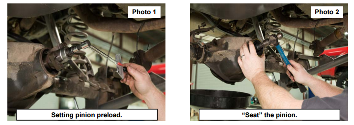
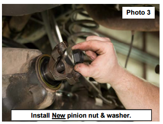
Pinion bearing preload is measured in inch-pounds, and is a measure of the rolling resistance of the pinion bearings after proper torque has been applied to the pinion nut. Set the preload carefully (see “Set Up Specifications”) so that the bearings will have a long life. Use oil on the pinion nut washer surface during all assemblies and red Loctite on the pinion nut threads during the final assembly.
Crush Sleeve Design: If you are unsure about getting the correct pinion depth, it may be easier to install the pinion without a crush sleeve until the correct pinion depth has been established. Always use a new crush sleeve for final assembly. Slide the crush sleeve on the pinion shaft and install the pinion through the rear of the housing. The yoke usually must be tapped on while applying pressure on the pinion gear head to hold it in place. Use an impact wrench or huge breaker bar to apply the torque necessary to crush the sleeve. Proceed very slowly so that you don’t overload the bearings. The pinion preload will be zero until the bearings contact the races but will then increase very quickly. Use an inchpound torque wrench to check the preload. If the pinion bearing preload exceeds the specified allowable range, install another new crush sleeve and start over.
Preload Shim Design: Clean the shims completely so that there are no particles that may cause a false preload reading or cause the shim stack to change thickness over time as the vehicle is driven. Slide the shim pack over the pinion shaft to the shelf. Use the original shims on the first assembly or add 0.003″ to the original preload shims to make up for the bearings settling into the housing. Tighten the pinion nut to approximately 250 foot pounds. Go slowly so as not to damage the bearing if the preload shim stack is not thick enough. Use an inch-pound torque wrench to check the preload. If the preload is too loose then remove shims so that the bearings will be tighter against the races and increase the preload. If the preload is too tight then remove the pinion gear and add shims so that the bearings will not be as tight against
the races.
All Designs: After reaching the correct preload, moderately tap both ends of the pinion to seat the bearings, races and yoke. Be careful not to hit the pinion so hard that it damages the bearings. After “seating” the pinion, check the pinion
bearing preload again.
Install Carrier and Adjust Carrier Preload and Backlash
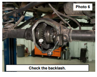
Carrier bearing preload is not specifically measured, but a good tight fit is important in all differential designs. Inadequate carrier bearing preload allows the carrier to move when under load and this can cause the backlash to open up. Check
the backlash by mounting a dial indicator to the housing with the plunger set perpendicular to the ring gear teeth. Hold the pinion yoke and rotate the ring gear back and forth. See the specifications section. The backlash will generally
change about 0.007″ for each 0.010″ that the carrier is moved. To decrease the backlash, move the carrier closer to the pinion centerline. To increase the backlash, move the carrier away from the pinion centerline.
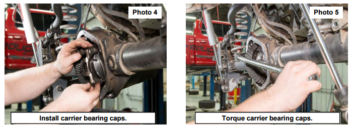
Screw Adjuster Design: Oil the adjuster threads on both the housing and on the adjusters themselves. While holding the races on the bearings, place the carrier in the housing. Install the carrier caps according to the marks made during
disassembly so that the threads are seated evenly on the adjusters. Third member differential designs require a 10 to 12 inch spanner wrench to tighten the adjusters. Chrysler differential designs require an extension bar and special spanner to access the adjusters through the axle tubes. Tighten both the left and right adjusters evenly by hand until they are fairly tight. If the backlash is too wide, tighten the left adjuster until the backlash is correct. If the backlash is too tight,
tighten the right adjuster until the backlash is correct. If necessary, open one adjuster and tighten the other. Both adjusters must be fully hand tightened when acceptable backlash is obtained. The final adjustment should tighten the left adjuster since the ring gear is forced away from the pinion gear while under load.
Shim Design: Some differentials use shims between the carrier bearing races and the housing and some use shims between the carrier bearing and the carrier case. Carrier bearing preload is established by the tightness of the shims.
The carrier should be shimmed tight enough that it must be tapped in with a plastic dead blow hammer. While holding the races on the bearings (and outside shims on the races) start the carrier into the housing and tap it in with the hammer.
Install the carrier caps according to the marks made during disassembly. Check the backlash. If the backlash is too wide, move or add shims to the left side. If the backlash is too tight, move or add shims to the right side. (If the carrier is
snug, move and replace the same thickness; if the carrier is too tight or too loose, remove or add shims accordingly.)
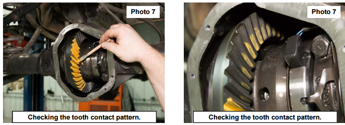
Checking the Pattern
Check the pattern for proper pinion depth only after setting the backlash. Brush three or four of the ring gear teeth with a moderate coat of gear marking compound in two different places on the ring gear. Rotate the ring gear past the pinion gear three or four times and then back so the pattern can be seen.
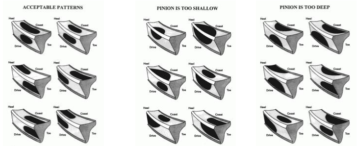
Pinion depth is indicated by the position of the pattern between the face and flank of the ring gear teeth. Backlash must be kept within specifications, and will therefore only slightly affect the pattern between the heel and toe of the ring gear
teeth. Housing alignment and pinion bearing bore alignment can also affect the pattern from heel to toe and can not be corrected without machine work. In some cases an ideal heel to toe pattern can not be achieved. If the backlash is within
specifications, you may disregard the heel to toe pattern. A contact pattern that is centered from face to flank always indicates correct pinion depth even if a pattern that is centered from heel to toe can not be obtained.
If the contact pattern is towards the face of the ring gear teeth then the pinion is too far away from the ring gear. Adjust the pinion shims to move the pinion gear towards the ring gear centerline (add shims; subtract shims for pinion support
designs). If the contact pattern is towards the flank of the ring gear teeth then the pinion is too close to the ring gear. Adjust the pinion shims to move the pinion gear away from the ring gear centerline (subtract shims; add shims for pinion
support designs).
When changing the pinion depth, make large changes (0.005″ to 0.015″) until the pattern is close. By making adjustments that move the pinion too far, you can determine that the correct pattern is somewhere between the two extremes.
Then make smaller changes (0.002″ to 0.004″) until the pattern is centered between the face and the flank of the ring gear teeth.
Gear Oil, Additive and Break-In
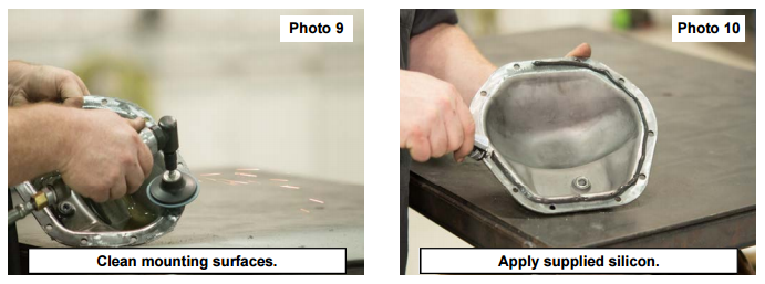
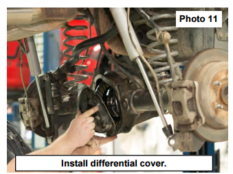
Use a gasket or 100% silicone to seal the cover or third member to the housing. Use only high quality name brand gear oil and fill the differential until the oil spills out the plug hole. We DO NOT recommend using synthetic oil with any clutchtype
Limited-Slip/Posi Differentials. Clutch-type positraction carriers require conventional oil and friction modifier (additive) to function correctly.
All new gear sets require a break-in period to prevent damage from overheating. After driving the first 15 or 20 miles youmust let the differential cool for 30-40 minutes before proceeding. Drive 500 easy miles before towing. Tow for very short
distances (less than 15 miles) and let the differential cool before continuing during the first 45 towing miles. Change the gear oil after the first 500 miles. This will remove any metal particles or phosphorus coating that has come from the new
gear set.
Any overloading or overheating can cause the gear oil to breakdown
and the Ring & Pinion can fail
THANK YOU FOR CHOOSING ROUGH COUNTRY SUSPENSION FOR YOUR SUSPENSION NEEDS.
