 FREE 1 to 3-Day Delivery on Orders $119+ Details
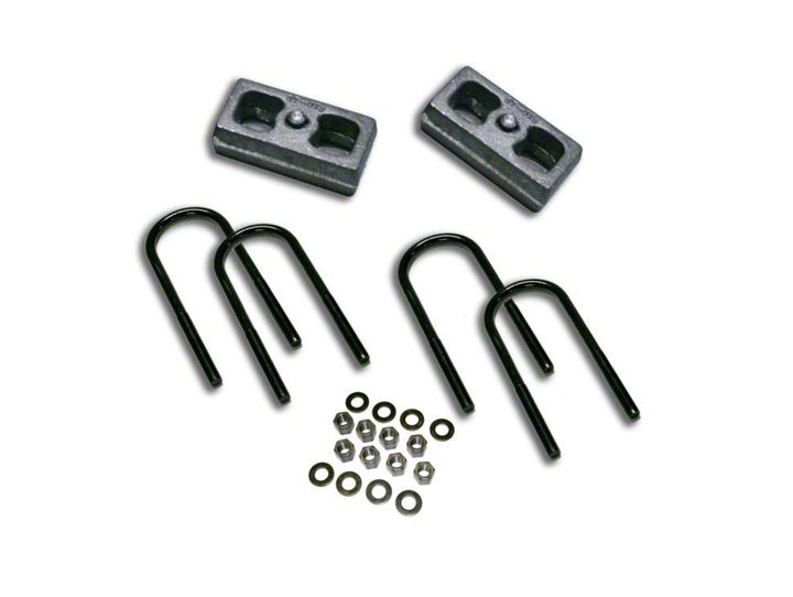
How to Install SuperLift 1.5 in. Rear Lift Block Kit (97-03 4WD) on your Ford F-150
Shop Parts in this Guide
INTRODUCTION
Installation requires a professional mechanic. Prior to beginning, carefully inspect the vehicle’s suspension, steering, driveline, and brake systems. Closely inspect all suspension-to-frame attaching points for stress cracks. The overall vehicle must be in excellent working condition; repair or replace all worn parts.
Read instructions several times before starting. Be sure you have all needed parts and know where they install. Read each step completely as you go.
NOTES:
A factory service manual should be on hand for reference. The manual will contain fastener torque specs, assembly techniques, and special tool requirements that are unique to this particular year and model vehicle.
Do not add or fabricate any components to gain additional suspension height.
Superlift lift blocks are not designed nor intended to be used on the front axle of any vehicle. The lateral stresses generated when turning will often cause blocks to roll-out from under the leaf springs. Also, lift block taper alters front end alignment which can make the vehicle dart, drift, and wander.
Use the check-off box “” found at each step to help you keep your place. Two “” denotes that one check-off box is for the driver side and one is for the passenger side. Unless otherwise notes, always start with the driver side.
1) PREPARE VEHICLE...
Raise rear of vehicle with a floor jack positioned under the rear axle. Place jack stands under the frame rails, a few inches in front of the rear springs’ front hangers. Ease the jack down until the frame is resting on the stands. Keep a slight load on the jack. Chock front tires to prevent accidental movement.
2) DISASSEMBLY...
Remove the tires. If the shock absorbers are not being replaced (if they are long enough and are in good condition), you should be able to leave them attached. If not, remove the shock absorbers.
Remove the spring-to-axle U-bolts. Use the jack to carefully lower the axle down enough for block installation. Do not overextend the brake and axle vent hoses, or any wiring; all may need rerouting or replacing.
3) INSPECT LIFT BLOCK CONTACT AREA...
When a vehicle is factory equipped with lift blocks, generally the factory blocks have an arm that acts as a contact point for the compression travel stop. If this is the case, normally the Superlift block is positioned under the factory spacer so the amount of available compression travel is unchanged. Placing the Superlift on top of the factory block increases compression travel (as long as other components, such as shock absorber or spring length, do not limit travel first.) Check the block-to-spring perch contact area; see the WARNING below. If the contact area is unsatisfactory, place the Superlift block on top of the factory block and inspect. If this top side positioning is used, consider that you are increasing allowable compression travel. You may need to limit compression travel by relocating or replacing the factory compression travel stops. This depends on block height, tire size, and how the vehicle is used.
WARNING - Sometimes the shape and design of the factory spring perch (where the springs or blocks seat on the axle) does not allow a good Superlift block-to-perch match. Check to be sure that the blocks’ entire surface area makes contact with the perches. Cast perches that are “honeycomb” or have recessed areas are prime candidates for seating problems. Also, some spring perches are prone to collapse or warp, especially toward the ends. Without a proper contact area or a flat mounting surface the blocks may fail or roll-out, causing the axle to detach from the springs. If necessary to ensure proper seating, re-plate the top of the perches with 1/4” thick steel (or something similar) or replace the perches completely.
4) INSTALLATION AND ASSEMBLY...
Clean all contact points. Install the Superlift blocks with the tall end of taper facing rearward. Be sure that all pins and holes are correctly sized and align properly. Position the spring-to-axle U-bolts and install the furnished U-bolt flatwashers. Evenly tighten the U-bolts using an “X” tightening pattern. Do not fully tighten the U-bolts, they are torqued later when the suspension is supporting vehicle weight.
Install new shock absorbers or reconnect old shocks (if applicable). Install tires; reference the factory service manual for proper lug nut torque specs and tightening sequence.
5) INSPECTION AND FINAL STEPS...
With the jack stands still in place beneath the frame rails, lower the jack and let the suspension hang at full extension travel. Manually rotate the driveshaft and check for shaft bind. Check driveshaft length. Generally, there should be at least 1-3/4” of spline contact when at full extension travel. Again, check the length of the brake hose, axle vent hose, etc..
See what is limiting suspension extension travel. Consider that in off road situations, when on radically uneven terrain, one fully compressed leaf spring can force the opposite spring to extend several inches beyond its unloaded “hanging” point. With this in mind, are you sure that the shock absorbers are long enough? If equipped with an anti-sway bar, will the bar drop links severely limit travel? If so, consider lengthening the factory links or purchasing longer ones. Are extension travel limiting straps needed to protect the shocks or other components? Ideally, travel should only be limited by the leaf springs, not by any other components.
Remove the jack stands and lower vehicle to the floor.
With the suspension supporting vehicle weight, torque the U-bolts as follows using a “X” tightening pattern:
NOTE: These torque specifications are for Superlift U-bolts used with Superlift Nylon inserted (Nyloc) lock nuts. Other grade U-bolts and fasteners may have different specifications.
1/2” rod diameter ........ 86 ft. lbs.
9/16” rod diameter .... 120 ft. lbs.
5/8” rod diameter ....... 185 ft. lbs.
6) SAFETY DECAL...
Install “Warning to Driver” decal. Refer to the “NOTICE TO DEALER AND VEHICLE OWNER” section below.
