FREE 1 to 3-Day Delivery on Orders $119+ Details
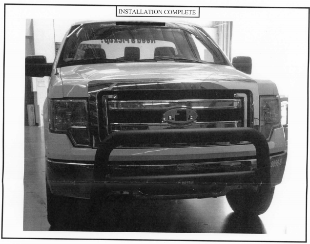
How to Install Westin Contour 3.5 in. Bull Bar - Black on your F-150
Procedure
1. Remove contents from box, verify if all parts listed are present and free from damage. Carefully read and understand all instructions before attempting installation. Failure to identify damage before installation could lead to a rejection of any claim.
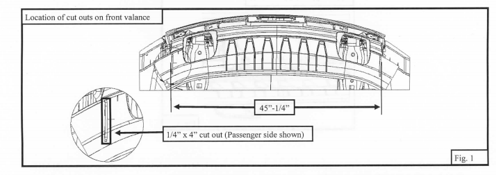
2. Start installation on the driver side from under the front of the vehicle. NOTE: Trimming of the front valance is required in order to install the lower mounting brackets. From outer flange to outer flange, the lower brackets should measure 45"-1/4". The approximate dimensions for the cut outs are shown in Figure 1. (NOTE: Trim as necessary)
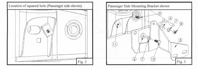
3. Clip the supplied Ml O clip nut to the slot right above the square hole in the vehicles frame channel. Make sure that the threaded hole is concentric with the square hole below the slot. Refer to Figure 2.
4. Locate the lower mounting bracket and place it up against the frame channel, making sure to align the two holes of the bracket with the side holes in the frame channel. Loosely secure the rear bracket hole to the clip nut using (I) Ml O
l.50X30MM hex head cap screw, (l)MlO split lock washer, (l)MlO small flat washer. Secure the bracket's front hole using (1) MI0-1.50X140MM hex head cap screw, (1) MIO small flat washer, (1) MIO split lock washer, and (1) MlO hex nut. Refer to Figure 3.
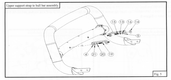
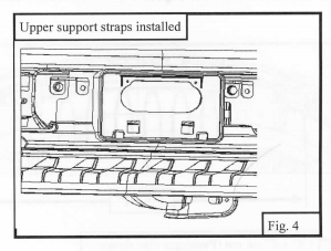
5. Loosely secure one end of the upper support strap to the vehicle using the supplied M 12 hardware. Refer to Figure 4.
6. Repeat steps 3-5 for passenger side.
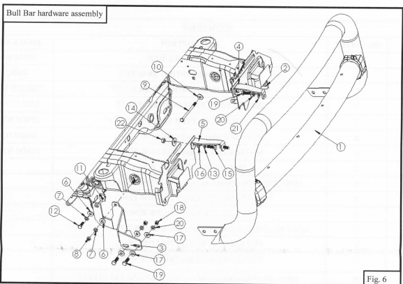
7. With assistance, hold the bull bar up in position on the outside of the lower mounting brackets. Loosely attach the bull bar to the brackets using ( 4) Ml 0-1.50X35 hex head cap screws, (8) M 10 medium flat washer, ( 4) Ml O split lock washers, and
( 4) MIO hex nuts. Refer to Figure 6 for a picture showing the mounting hardware.
8. Loosely attach the other end of the support strap to the bull bar using (2) Ml O-I .50X35 hex head cap screws, (2) MI 0 split lock washers, and (2) Ml O small flat washers. Refer to Figure 5.
9. Align and adjust the bull bar as necessary. Tighten and torque all Ml O hardware to 25 ft-lbs and Ml 2 hardware to 55 ftlbs.