FREE 1 to 3-Day Delivery on Orders $149+ Details
How to Install a Accel Performance Tach Adapter on your 1984-1995 Mustang
Installation Time
2 hours
Tools Required
- Metric Socket Set
- Ratchet
- Torx T-30 Socket
- 10mm Socket (12 point)
- Snap Ring Pliers
- 1½" Open Ended Wrench
- Camshaft Degree Kit
Installation
GENERAL INFORMATION
The features of the 275 and 300 Ignitions are the same, with one exception: the 300 includes a single stage RPM limiter.You can set various RPM limits using switches that are accessible through the end plate. See page 4 of this instruction book for more information about the rev limiting features of the 300 .
Battery
The 275 and 300 Ignition Controls operate on any negative ground, 12 volt electrical system with a distributor. It will also work with 16 volt batteries and can withstand a momentary spike of 24 volts in case of jump starts. This system delivers full voltage with a supply of 10-18 volts, and operates with a supply voltage as low as 8 volts. If your application does not use an alternator, allow at least 15 amp/hour for every half hour of operation. If you crank the engine with the same battery or other accessories, such as an electric fuel or water pump, increase the amp/hour rating.
Coils
For optimum performance with your 275 or 300 Ignition Controls, we recommend ACCEL P/N 140019 Coil, as well as most stock coils or aftermarket coils designed as stock replacements or CD-type coils. NOTE: Do not use ACCEL’s Drag Race Coil P/N 140010. Tachometers
The green wire on the 275 and 300 Ignition Controls provides a trigger signal for tachometers, shift lights, or other add-on RPM activated devices. This wire produces a 12 volts square wave signal with a 20% duty cycle. Some vehicles with factory tachometers may require a tach adapter to work with the 275 and 300 Ignition Controls. If your GM vehicle uses an inline filter, it may cause the tach to drop to zero on acceleration. If this occurs, bypass the filter. For more information on tachometers, see page 3.
Spark Plugs
Using the correct spark plug and heat range is important for optimum performance. Because there are so many variables to consider, we suggest starting with your engine manufacturer’s spark plug recommendation. From there, you can experiment with small changes in plug gap and heat range to obtain the best performance from your engine.
Foreign Vehicles
Because of modern fuel injection systems, some foreign vehicles may require a tachometer/fuel injection adapter to work with the 275 or 300 Ignition Controls.
NOTE: Do not install the 275 or 300 Ignition Controls on any vehicle that is originally equipped with a CD ignition control.
Spark Plug Wires
High quality, spiral wound wire and proper routing are essential to the operation of the 275 and 300 Ignition Controls. This type of wire provides a good path for the spark to follow while minimizing electromagnetic interference (EMI).
NOTE: Do not use solid core spark plug wires with the 275 or 300 Ignition Controls.
Routing
Wires should be routed away from sharp edges, moving objects, and heat sources. Wires that are next to each other in the engine’s firing order should be separated. For example, in a Chevy V8 with a firing order of 1- 8- 4- 3- 6- 5- 7-2, the #5 and #7 cylinders are positioned next to each other on the engine as well as in the firing order. Voltage from the #5 wire could jump to the #7 wire. This could cause detonation and engine damage.
For added protection against cross-fire, ACCEL offers PRO SLEEVE insulated sleeving. PRO SLEEVE is a glass woven, silicone coated protective sleeve that slides over your plug wires. It also helps reduce damage from heat and sharp objects.
MISCELLANEOUS INFORMATION
Sealing
Do not attempt to seal the 275 or 300 Ignition Controls. All of the circuits of a 275 and 300 receive a conformal coating of sealant that protects the electronics from moisture. Sealing the 275 and 300 will not allow any moisture that seeps in through the grommets to drain and may result in corrosion.
Welding
To avoid any damage to the 275 or 300 Ignition Controls when welding on the vehicle, disconnect both the 4-pin flat and 4-pin square connectors. It is also a good idea to disconnect the tachometer ground wire as well.
Distributor Cap and Rotor
We recommend installing a new distributor cap and rotor when installing the 275 or 300 Ignition Controls. Be sure the cap is clean inside and out, especially the terminals and rotor tip. On vehicles with smaller caps, it is possible for the air inside the cap to become electrically charged causing crossfire which can result in misfire. You can prevent this by drilling a couple of vent holes in the cap.
Drill the holes between terminals at rotor height, facing away from the intake. If needed, place a small piece of screen over the holes to act as a filter.
275 Diagnostic LED
Behind the end panel of your 275 ignition there is a red LED indicator. This serves two purposes: when you first turn on the ignition switch, the LED will flash rapidly 2 times. This indicates that the ignition system has power, and that the microprocessor is running properly. In addition, the LED will flash when receiving a proper trigger signal from the vehicle.
If, after a normal power-up, the LED doesn’t flash when cranking the engine, you should check your triggering circuit for problems. If the LED flashes when the engine is cranked, but there is still no spark, the problem lies somewhere else.
275 Cylinder Selection Only
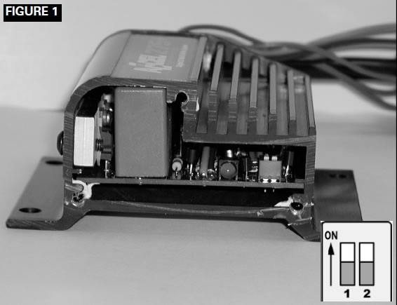
Your 275 Ignition comes from the factory set up for 8 cylinder operation. If you want to use this ignition with a 4 or 6 cylinder engine, you must first remove the three screws that hold the endplate opposite the wire harness end. Once the endplate is removed, you’ll see the end of the circuit board. Look for the two-section switch. To select 4 cylinder mode, move the switch marked "1" to the "ON" position. To select 6 cylinder mode, move the switch marked "2" to the "ON" position. If both switches are "OFF", or both are "ON", the ignition will run in the 8 cylinder mode. See Figure 1. For operation of the 300 cylinder selection, see page 4.
MOUNTING
The 275 or 300 Ignition Controls can be mounted in any position. If you mount it in the engine compartment, keep it away from moving objects and heat sources. The most convenient method for mounting is with the wire harness end down. This ensures easy access to the cylinder selection, and on the 300 the rev limiter selection switches. Do not mount the unit in a closed area, such as the glovebox. Also, do not mount the control box next to the distributor or spark plug wire. This will eliminate any possibility of false trigger signals.
When you find a suitable location to mount the unit, make sure all wires of the ignition reach their connections. Hold the ignition in place and mark the location of the mounting holes. Mount the 275 or 300 using the mounting hardware included in the kit.
WIRING
Wire Length
All of the wires of the 275 or 300 Ignition Controls may be shortened as long as quality connectors are used or soldered in place. To lengthen the wires, use one size larger gauge wire (16 gauge). Use the proper connectors to terminate all wires. All connections must be soldered and sealed.
Grounds
A poor ground connection can cause many frustrating problems. When a wire is specified to go to ground, connect it to the chassis or engine. Always connect a ground strap between the engine and chassis. Connect any ground wires to a clean, paint-free metal surface.
Ballast Resistor
Remove or bypass any ballast resistor or resistor lead if so equipped.
WIRE FUNCTIONS
Trigger and Coil Leads
Red Connects to a switched 12 volt source, such as the ignition key.
Yellow Connects to the positive ( ) terminal of the coil.
NOTE: This is the only wire that makes electrical contact with the coil positive ( ) terminal.
Brown Connects to the negative (–) terminal of the coil.
NOTE: This is the only wire that makes electrical contact with the coil negative (-) terminal.
Trigger Wires Either of two circuits will trigger the 275 or 300 Ignition Controls: a points or OE trigger circuit (white wire) or a magnetic pickup circuit (violet and orange wires).
NOTE: The two circuits will never be used together.
White Connects to points, electronic ignition amplifier output or to the OE module trigger circuit. When this wire is used, the magnetic pickup connector is not used.
Violet/Orange Connect to factory magnetic pickups or other aftermarket pickups. The orange wire is positive ( ) and the violet is negative (–).
When these wires are used, the white wire is not used. Consult the chart that shows the polarity of other common magnetic pickups. Green Connects to an aftermarket tachometer.
ROUTING WIRES
Route all wires away from heat sources, sharp edges, and moving objects. Route the trigger wires separate from the other wires and spark plug wires and direct away from the distributor. If possible, route them along a ground plane, such as the block or firewall, which creates an electrical shield. The magnetic pickup wires should be routed separately and twisted together to help reduce extraneous interference.
WARNING:The 275 and 300 Ignition Controls are capacitive discharge ignitions. High voltage is present at the coil primary terminals. Do not touch these terminals or connect test equipment to them.
COMMON COLORS FOR MAG PICKUP WIRES
| Distributor | Mag | Mag – |
|---|---|---|
| Mallory Crank Trigger | Purple | Green |
| Mallory Billet Competition Distributor, Series Nos. 81 and 84 | Orange | Purple |
| Mallory COMP® 9000 Series Nos. 96-99 | Orange | Purple |
| Mallory Harness P/N 29040 | Red | Black |
| MSD | Orange/Black | Violet/Black |
| MSD Crank Trigger | Orange/Black | Violet/Black |
| Ford | Orange | Purple |
| Accel 46/48000 Series | Orange/Black | Violet/Black |
| Accel 51/61/71000 Series | Red | Green |
| Chrysler | Orange/White | Black |
PRE-START CHECKLIST
- The only wires connected to the coil terminals should be the yellow connected to coil positive ( ) and brown connected to coil negative (–).
- The red wire is connected to a switched 12 volts source, such as the ignition key.
- If you’re not using an alternator, the battery should be connected and fully charged.
- The engine is equipped with at least one ground strap to the chassis.
TROUBLESHOOTING
This section offers several tests and checks you can perform to ensure proper installation and operation of the 275 or 300 Ignition Controls. If you experience a problem with your 275 or 300 , first check for proper installation and poor connections. You can eliminate many problems by checking these items. If you have any questions concerning your 275 or 300 Ignition Controls, contact the ACCEL Technical Service Department at 216.688.8300 ext. 5, Monday through Friday, 8:30 am to 5:00 pm Eastern Standard time.
Tach/Fuel Adapters
If your tachometer does not operate correctly, you probably need an ACCEL or Mallory tach adapter. Consult the Tachometer Compatibility List at right for common tachometers and compatible tach adapters.
No-Run on Foreign Vehicles
Some foreign vehicles with fuel injection systems may require a tachometer/fuel injection adapter to run with the 275 or 300 Ignition Controls. Often, the same trigger source is used to operate an ignition, tachometer, and fuel injection. This results in a voltage signal that is too low to trigger the fuel injection. A tach/fuel injection adapter will usually solve this problem.
InoperativeTachometers
If your tachometer fails to operate with the 275 or 300 installed, you may need an ACCEL or Mallory tach adapter. Before purchasing a tach adapter, try connecting your tachometer trigger wire to the green wire of the 275 or 300 Ignition Controls. This output produces a 12 volt, square wave. If the tach still does not operate, you will need a tach adapter.
Two different tach adapters are available:
Mallory If you are using the magnetic pickup P/N 29078 connector (green and violet wires) to trigger the 275 or 300 , you will need this adapter.
ACCEL If your tach was triggered from the coil P/N 49365 negative terminal (voltage trigger) and you are using the white wire to trigger the 275 or 300 , you will need this adapter.
TACHOMETER COMPATIBILITY LIST
| Aftermarket Tachometer | White Wire trigger | Magnetic Trigger connector |
|---|---|---|
| Autogage | 49365 | 29078 |
| Autometer | — | — |
| Ford Motorsport | — | — |
| Moroso | — | — |
| Stewart | 49365 | 29078 |
| S.W. & Bi Torx | — | — |
| Sun | 49365 | 29078 |
| VDO | N/A | 29078 |
| AMC (Jeep) | 49365 | 29078 |
| Chrysler | 49365 | 29078 |
| Ford (Before 1976) | 49365 | 29078 |
| Ford (After 1976) | 49365 | 29078 |
| GM | Bypass in-line filter | Bypass in-line filter |
| Imports | 49365 | 29078 |
Misses and Intermittent Problems
Experience has shown that if your engine is misfiring or hesitating at higher RPM, it is usually not an ignition controller problem. Most common causes include a coil or plug wire failure, arcing from the cap or boot plug to ground or spark ionization inside the cap. Perform the following checks:
- Inspect the plug wires at the cap and at the spark plug for a tight connection. Visually inspect for cuts, abrasions, or burns.
- Inspect the primary coil wire connections. Because the 275 and 300 Ignition Controls receive a direct 12 volt source from the battery, there will not be any voltage at the coil positive ( ) terminal, even with the key turned on. During cranking, or while the engine is running, very high voltage will be present and no test equipment should be connected.
WARNING: Do not touch the coil terminals during cranking or while the engine is running.
- Make sure that the battery is fully charged and the connections are clean and tight. If you are not running an alternator, this is an imperative check. If the battery voltage drops below 10 volts during a race, the 275 or 300 Ignition Controls output voltage will drop.
- Is the engine running lean? Inspect the spark plugs and the entire fuel system.
- Check all wiring connections for corrosion or damage.
Remember to use proper connections followed by soldering, then seal the connections completely.
If everything checks positive, use the procedure below to test the ignition for spark. Mallory offers an Ignition Tester (P/N 28357) that allows you to check the entire ignition system while it is installed in the vehicle. This tool also checks operation of RPM limits, activated switches, and shift lights.
CHECKING FOR SPARK
If triggering the ignition with the white wire:
1. Make sure the ignition switch is in the "OFF" position.
2. Remove the spark plug coil wire from the distributor cap and set the terminal approximately 1/4" from ground.
3. Disconnect the 275 or 300 Ignition Control’s white wire from the distributor’s points or ignition amplifier.
4. Turn the ignition to the ON position. Do not crank the engine.
5. Tap the white wire to ground several times. Each time you pull the wire from ground, a spark should jump from the coil wire to ground. If spark is present, the ignition is working properly. If there is no spark, skip to Step 6 below.
If Triggering With the Magnetic Pickup:
1. Make sure the ignition switch is in the OFF position.
2. Remove the spark plug coil wire from the distributor cap and set the terminal approximately 1/4" from ground.
3. Disconnect the 275 or 300 Ignition Controls magnetic pickup wires from the distributor.
4. Turn the ignition to the ON position. Do not crank the engine.
5. With a small jumper wire, short the 275 or 300 Ignition Control’s green and violet magnetic pickup wires together.
Each time you break this short, a spark should jump from the coil wire to ground. If spark is present, the ignition is working properly. If there is no spark skip to Step 6 below.
6. If there is no spark:
A. Inspect all of the wiring.
B. Substitute another coil and repeat the test. If there is now spark, the coil is at fault.
C. If there is still no spark, check to make sure there is 12 volts on the small red wire from the 275 or 300 Ignition Controls when the key is in the ON position. If 12 volts is not present, find another switched 12 volts source and repeat the test.
D. If after following the test procedures and inspecting all of the wiring there is still no spark, the 275 or 300 Ignition Controls are in need of repair. See the Warranty and Service section for information.
ACCEL 300 RPM LIMITER SETTINGS ONLY
Note the sticker attached to the front of the 300 . This sticker shows settings for number of cylinders and RPM limits. In case the sticker becomes damaged or otherwise unreadable, the settings are shown at right.
ACCEL 300 Cylinder Selection Only
Your 300 Ignition comes from the factory set up for 8-cylinder operation. If you want to use this ignition with a 4- or 6-cylinder engine, you must first remove the three screws that hold the end plate opposite the wire harness end. Once the end plate is removed, you will see the end of the circuit board. Look for the four selection DIP switches. To select 4-cylinder mode, move DIP switch #2 up. To select 6-cylinder mode, move DIP switch #3 up. See Figure #2.
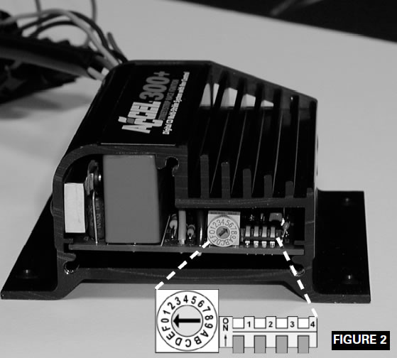
Setting Switch #4
This switch should be set DOWN for normal operation. If you are using a compatible external RPM limiter, such as the ACCEL 375 Multi-Function Accessory, this switch should be set to the UP position.
CAUTION: Using the ACCEL 300 with an external RPM limiter AND switch #4 in the DOWN position could cause engine damage!
| Rotary Switch Position | DIP Switch #1 DOWN | DIP Switch #1 UP |
|---|---|---|
| 0 | 4,500 | 8,500 |
| 1 | 4,750 | 8,750 |
| 2 | 5,000 | 9,000 |
| 3 | 5,250 | 9,250 |
| 4 | 5,500 | 9,500 |
| 5 | 5,750 | 9,750 |
| 6 | 6,000 | 10,000 |
| 7 | 6,250 | 10,250 |
| 8 | 6,500 | 10,500 |
| 9 | 6,750 | 10,750 |
| A | 7,000 | 11,000 |
| B | 7,250 | 11,250 |
| C | 7,500 | 11,500 |
| D | 7,750 | 11,750 |
| E | 8,000 | 12,000 |
| F | 8,250 | NO LIMIT |
| Number of Cylinders | Switch #2 | Switch #3 |
|---|---|---|
| 4 | UP | Down |
| 6 | Down | UP |
| 8 | Down | Down |
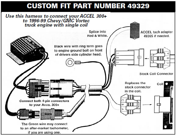
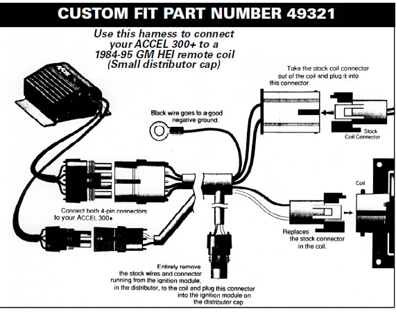
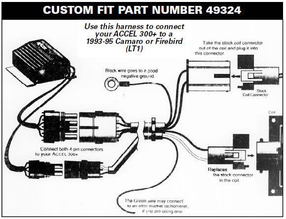
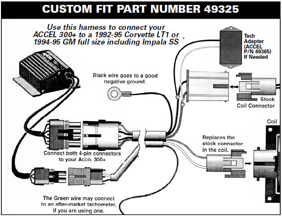
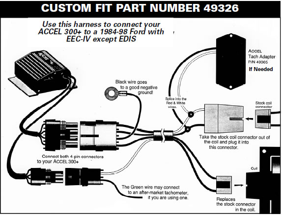
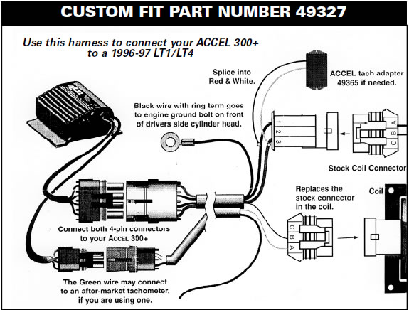
CUSTOM FIT APPLICATION - PLUG-IN HARNESS DIAGRAMS
Accel-Performance-Tach-Adapter-(84-95-All)
Accel-Performance-Tach-Adapter-(84-95-All)