FREE 1 to 3-Day Delivery on Orders $119+ Details
Best Sellers


How to Install AEM Electronics AQ-1 OBDII Data Logger (96-17 All) on your Ford Mustang
The AEM AQ-1 Data Logger is the ideal entry level data logger for virtually all forms of racing and Motorsports because it installs easily, can read live parameters from ancillary sensors, AEMnet enabled devices, GPS and more, and put them into a single log make your data easy to view. Whether you race a late model EFI-equipped OR carbureted vehicle, the AQ-1 is the ideal solution for your data acquisition needs.
Features
· Four (4) 0-5VDC Analog Inputs with software selectable 2.2k pull-up resistor
· Four (4) 0-16.5VDC Analog / Frequency Inputs
· Three (3) Digital (Switch to Ground, 16V Max) Inputs
· Serial (RS-232) Input (AEM EMS / NMEA0183 GPS Only)
· AEMnet (CAN) Input (AEMnet Devices Only)
· 3-axis Internal Accelerometer /- 4g
· 1000Hz Maximum Logging Rate
· EnviroSeal Boot / Sealed Connector
· 2 GB SD Card (Supports up to 32GB)
· AQ-1 Data Acquisition System Configuration Software (USB)
· AEMdata Analysis Software
· OBD-II PID Input (CAN Only)
· OBD-II DTC Read/Clear (CAN Only)
Installation
Mounting
The AQ-1 is provided with a sealed main connector and EnviroSeal boot to cover the integrated USB port and SD card slot. Nevertheless, care should be taken to located the logger in a relatively clean, dry environment as it is not completely water-proof. The provided hardware and mounting template (included in this manual) may be used to mount the unit; alternatively, hook and loop fastener (not provided) may be used. It is acceptable to pierce the EnviroSeal boot to accommodate mounting hardware.
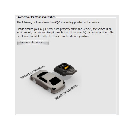
For the internal accelerometer to work properly, the AQ-1 must be mounted such that its largest surface (top or bottom) is either coincident with, or at a right angle to one of the primary axes of the vehicle. Please reference the accelerometer calibration section of this manual and/or the configuration software for more detail and images of acceptable orientations.
Electrical Wiring Installation
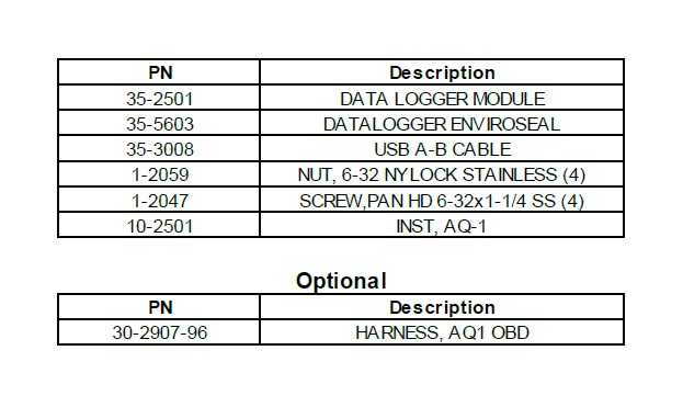
A wiring harness is not included with the 30-2501 kit, however the purchase and use of the AEM 30-2907-96 AQ-1 Data Logger Harness is highly recommended. This harness has been designed to ensure easy installation, signal integrity, and proper logger operation.
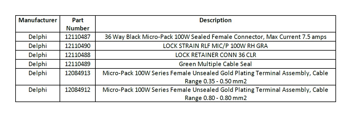
Only skilled, experienced installers should attempt to source and design their own harness. The connector part numbers (AEM does not supply these parts separately outside the 30-2906-96 or 30-2907-96) are provided below for this purpose.
Important Wiring Tips
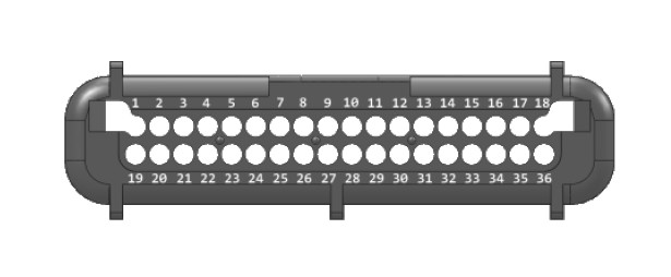
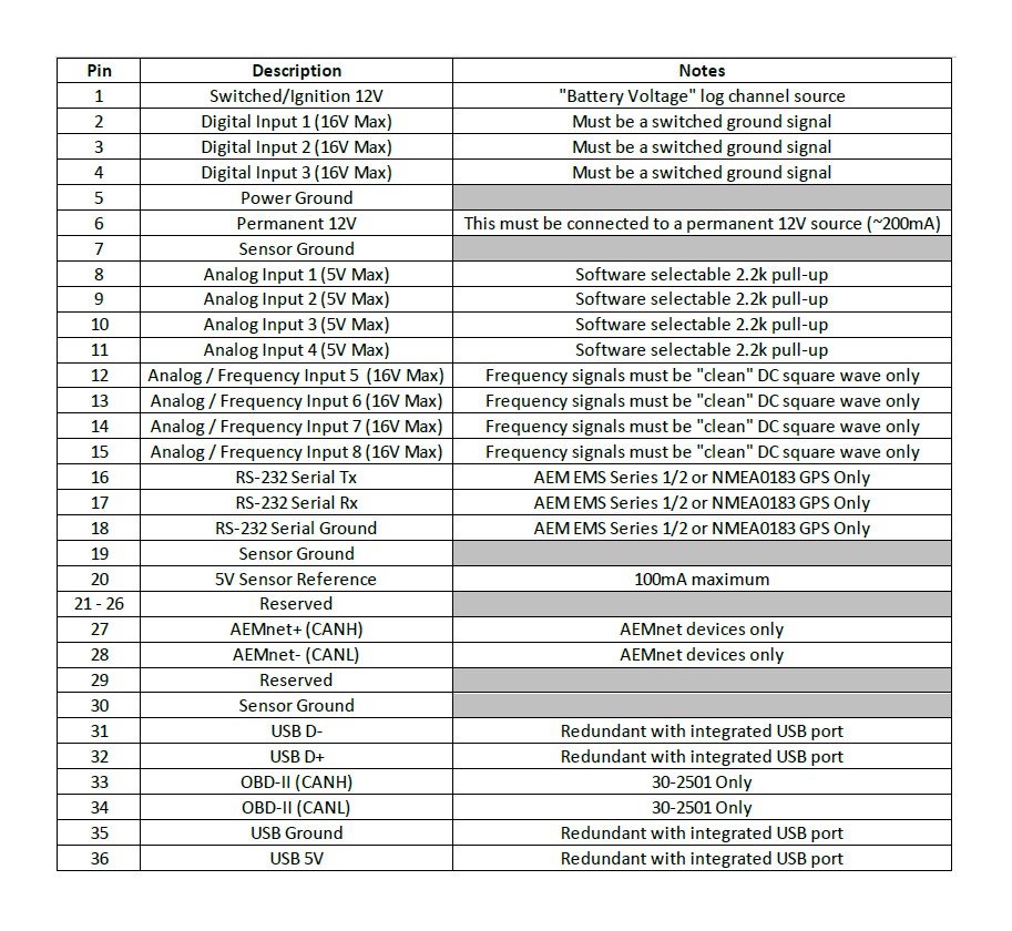
· Permanent 12V (Pin 6) must be connected to a constant 12V battery source that is not disconnected via a cut-off switch or similar.
· Switched/Ignition 12V (Pin1) must be connected to a switched ignition source that energizes when the vehicle is in use and is off when the vehicle is not in use.
· Frequency inputs (Pins 12-15) must only be connected to clean DC square wave signals. Connections to ignition coils or magnetic/VR sensors will damage the logger.
· CAN wiring (Pins 27-28, 33-34) must utilize twisted pairs with greater than one twist per inch.
· USB wiring (Pins 31-32, 35-36) is only required if users wish to mount a USB port remotely; the integrated USB port functions exactly the same. USB wiring requires special care; please contact the USB consortium (usb.org) for proper wiring conventions.
· Proper crimping, shielding, and harness routing practices should always be implemented.
Pinout
Wiring: Analog Input 1 - 4
This class of inputs is suitable for logging the output from a variety of sensors which have a continuously variable (analog) output between 0 and 5 Volts. A software selectable 2.2kOhm pull-up resistor is available.
Typical Automotive 0-5V Analog Sensors
· Throttle Position Sensor (TPS)
· Accelerator Pedal Position Sensor (APP)
· Manifold Absolute Pressure Sensor (MAP)
· Shock Travel Sensor
· Gear Position Sensor (GPS)
· AEM UEGO/AFR, Pressure, Temperature Gauges with 0 - 5V Outputs
· Mass Airflow Sensor (MAF) *Analog type only!*
· Engine Coolant Temperature (ECT)
· Engine Oil Temperature (EOT)
· Air Inlet Temperature (AIT)
· ...and many more!
The majority of these sensors are either "two wire" or "three wire" type sensors. Typically, these sensors will have a 1) signal ground wire, 2) signal wire, and sometimes 3) power (5V) wire. Wiring the sensor into the analog input of the AQ-1 logger is a matter of connecting one of the logger's analog inputs to the "signal" wire of the sensor. Please refer to the documentation that came with your sensor, gauge, or the factory service manual for your vehicle to locate and identify the appropriate signal wire.
Software Selectable 2.2kOhm Pull-Up Resistor
Analog inputs 1-4 are the only AQ-1 inputs that are equipped with a pull-up resistor. Pull-up resistors are required when using two wire sensors (RTD, thermistor, temperature sensors, e.g. ECT, EOT, AIT) that ARE NOT already wired to a second data system or ECU.
Yes, you need a pull-up resistor when
You want a log a pre-existing AIT sensor that's already wired to your engine management system or ECU.
No, you don't need a pull-up resistor when You want to log an AIT sensor that you purchased from a third party, like AEM, and installed in your intake and is not connected to any other ECU, EMS, logger.
Wiring: Analog / Frequency Input 4 - 8
This class of inputs is suitable for logging the output from a variety of sensors which have a continuously variable (analog) output or, optionally a DC frequency, between 0 and up to 16 Volts. These inputs do not have any pull-ups available.
Typical Automotive 0-5V Analog Sensors
· Throttle Position Sensor (TPS)
· Accelerator Pedal Position Sensor (APP)
· Manifold Absolute Pressure Sensor (MAP)
· Shock Travel Sensor
· Gear Position Sensor (GPS)
· AEM UEGO/AFR, Pressure, Temperature Gauges with 0 - 5V Outputs
· Mass Airflow Sensor (MAF) *Analog type only!*
· Engine Coolant Temperature (ECT)
· Engine Oil Temperature (EOT)
· Air Inlet Temperature (AIT)
· ...and many more!
The majority of these sensors are either "two wire" or "three wire" type sensors. Typically, these sensors will have a 1) signal ground wire, 2) signal wire, and sometimes 3) power (5V) wire. Wiring the sensor into the analog input of the AQ-1 logger is a matter of connecting one of the logger's analog inputs to the "signal" wire of the sensor. Please refer to the documentation that came with your sensor, gauge, or the factory service manual for your vehicle to locate and identify the appropriate signal wire.
No Pull-Up Resistor Available
Analog inputs 4-8 do not have any pull-up resistor available. Two wire sensors may only be connected to this input if they are connected to another data system or ECU within which there is a pull-up resistor.
Typical Automotive Frequency Type Sensors
· Engine Speed / Tachometer (RPM)
· Vehicle Speed Sensor (VSS)
· Mass Airflow Sensor (MAF) Frequency type
· Flow Sensor
· Flex Fuel Sensor
· Hall Effect Sensor
· Injector Duty Cycle
· Boost Control Solenoid
· ...and many more!
THIS INPUT ONLY ACCEPTS CLEAN DC SQUARE WAVE SIGNALS. DAMAGE TO THE LOGGER IS LIKELY TO OCCUR WHEN DIRECTLY CONNECTED TO COILS OR MAGNETIC SENSORS.
Engine Speed / Tachometer (RPM) / Vehicle Speed Sensor (VSS) / Hall Effect Sensor
The use of a tach adapter such as the MSD “Tach Signal GMR Pickup” Part Number #8918 is usually required when attempting to log engine rpm from high-voltage noisy sources.
Injector Duty Cycle / Boost Control Solenoid
Solenoids are typically two wire devices where 1) one wire is connected to battery voltage and the 2) second wire is connected to a low-side output of an ECU or controller -- wire 2) should be connected to this input for the purposes of logging.
Wiring: Digital Input 1 - 3
This class of inputs is suitable for logging the output from "switched to ground" digital signals with a maximum voltage of 16V.
Typical Automotive Digital Signals
· Clutch Switch
· Brake Switch
· Cooling Fan Switch
· Nitrous Solenoid
· Transmission Shift Solenoid (non-pulsed)
· Driver operated start/stop switch
· ...and many more!
Solenoids are typically two wire devices where 1) one wire is connected to battery voltage and the 2) second wire is connected to a low-side output of an ECU or controller or ground -- wire 2) should be connected to this input for the purposes of logging.
A start/stop switch typically has two terminals where 1) is to be connected to the logger and 2) is connected to ground.
Important Note: These inputs are not intended for use with solenoids or signal sources that are pulsed with a (high) frequency for the purposes of control or feedback.
Wiring: Serial/GPS
This input is only compatible with the AEM EMS Series 1/2 serial telemetry output or a serial (RS-232) NMEA0183 GPS receiver.
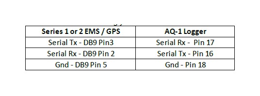
AEM EMS Series 1 / 2 Serial Telemetry
The 30-2906-96 or 30-2907-96 AQ-1 Harness comes with the appropriately wired DB9 connector that can simply be plugged into the Series 1 or 2 EMS.
The following connections should be made if constructing your own harness.
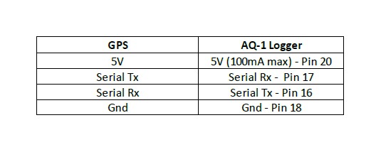
GPS Receiver - NMEA0183 RS-232 Serial
The following Garmin GPS receivers have been validated for use with the AQ-1
· Garmin GPS 18x PC – 1 Hz model with DB9 connector and 12 volt power adapter - The 30-2906-96 AQ-1 Harness comes with the appropriately wired DB9 connector that can simply be plugged into the Garmin GPS 18x PC.
· Garmin GPS18x 5Hz- 5 Hz OEM model - This unit will require wiring; please refer to Garmin documentation and the following pinout.
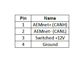
Wiring: AEMnet
The AQ-1 AEMnet is designed only to work with approved AEMnet devices; please reference the "Compatible AEM Products" section located within this manual. The 30- 2906-96/30-2907-96 AQ-1 Harness comes with an appropriately wired Deutsch DTM 4-pin AEMnet connector allowing easy connection to most AEMnet devices. The following AEMnet pinout is provided for users constructing their own harness.
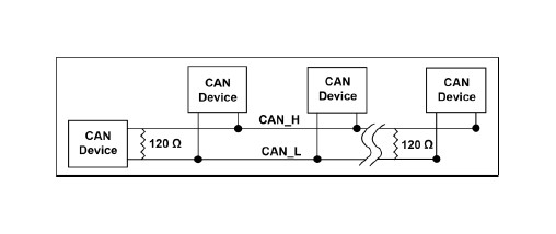
Termination,Wiring, and Resistors
Refer to the following guidelines when wiring AEMnet (CAN) devices.
· Twisted wire is required with >1 twist per inch.
· AEMnet buses must be properly terminated. Termination resistors are 120Ohms each, two total, located at the physical ends of the bus wires.
· The AQ-1 logger is equipped with a non-configurable 120Ohm resistor.
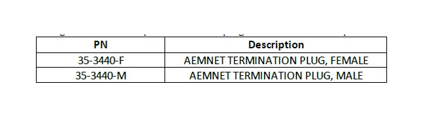
The following Deutsch DTM4-pin termination plugs are available from your AEMdealer.
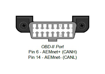
Wiring: OBD-II
THIS INPUT ONLY WORKS ON VEHICLES EQUIPPED WITH A CAN-BASED OBD-II SYSTEM, TYPICALLY 2008 AND NEWER VEHICLES.
The 30-2907-96 AQ-1 Harness comes with an appropriately OBD-II wired connector allowing easy connection to the vehicle's OBD port. The following pinout information is provided for users constructing their own harness.
Important Note: The AQ-1 should not be "piggy-backed" with other devices such as scan tools or reflash controllers. This input is not equipped with a termination resistor and none is required.
Configuration Software Overview
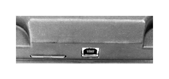
The AEM AQ-1 Data Logger is configured using PC software available for download at www.aemelectronics.com. Once downloaded and installed, connect the provided USB cable to the PC and the AQ-1.
The USB cable may be plugged either directly into AQ-1 itself or, if using the AEM 30-290x-96 harness, may be plugged in to the harness' USB connector -- they are electrically equivalent. Note: if this is the first time the AQ-1 is being used, please wait for Windows to recognize the device which, on some PCs may take up to sixty seconds; no additional drivers are necessary and a system restart is not typically required.
NOTE: The device can be powered by USB (alone) for certain configuration or viewing tasks. Certain functions or live readings will not be available, however, unless the AQ-1 is powered by a 12V system through its main connector.
The annotated image below shows the main user interfaces of the software.
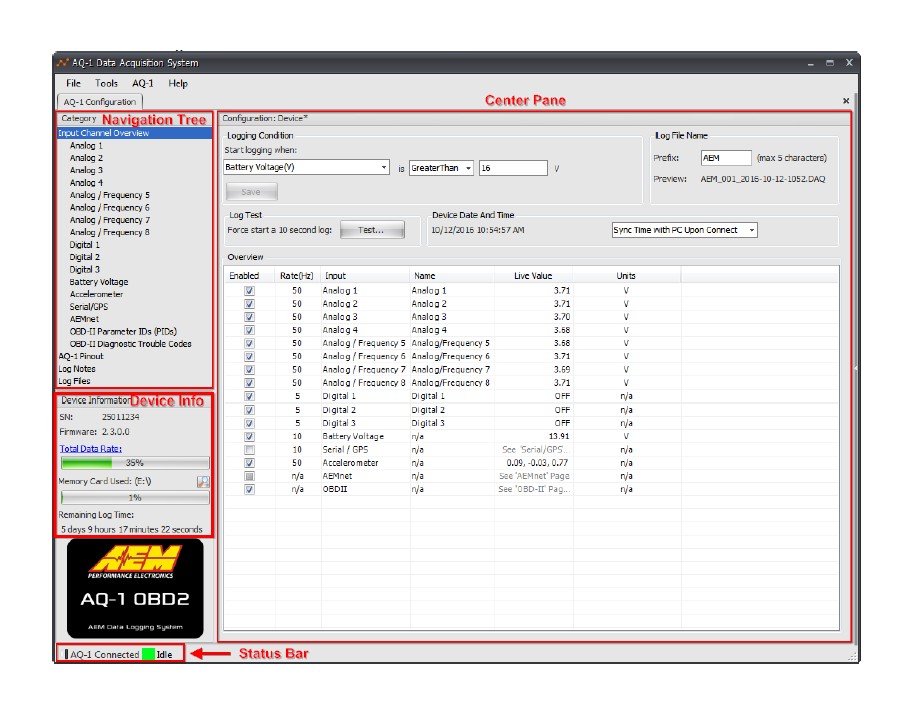
Navigation Tree
The Navigation Tree allows the user to switch between the available configuration pages. Each configuration page provides the available options for each of the logger's inputs or other feature. Click on the desired input/feature to navigate to its configuration page.
Center Pane
All configurable options or live readings from the device will be displayed in this area. Some information or options are only available when connected through USB to an AQ-1 that is powered by a 12V system through the main connector.
Device Information
When connected to an AQ-1 via USB, this area will display information about the device itself and its SD card if installed.
Status Bar
Displays the current connection and logging status.
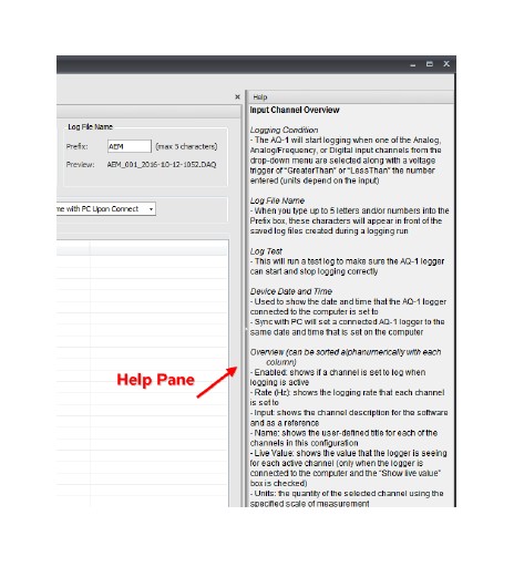
Help Pane
In addition to this manual, detailed information about the currently viewed page is available in the Help Pane located on the right side of the screen. The Help Pane may be collapsed when not needed using the slide control.
Important Notes to Remember When using Software
· Logger can be configured when powered by USB only but Permanent 12V at main connector is required for all live readings and functions to work properly
· Monitor the Status Bar to determine when the logger is actively logging; many functions will be disabled while logging is active to conserve resources
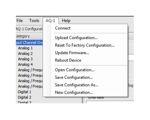
AQ-1 Pull-down Menu
Connect - Connects (or reconnects) to logger. Upload Configuration - Sends logger configuration from PC to the logger.
Reset To Factory Configuration - Resets connected logger's configuration to factory default settings.
Update Firmware - Do not perform unless instructed by AEM Technical Support.
Reboot Device - Performs a reboot of the currently connected logger. Not typically necessary.
Open Configuration - Open configuration from PC and edit offline.
Save Configuration - Save currently opened configuration to PC with same filename.
Save Configuration As - Save currently opened configuration to PC with different filename.
New Configuration - Create a new configuration offline and begin editing.
Configuration: Input Channel Overview / Logging Conditions
This page provides some important interfaces for configuring the operation of your logger. The following things should be considered when selecting and configuring logging conditions:
· Logging conditions should be selected such that there is a clear transition to and from logging mode. For example 'Engine RPM > 350' would provide a clear transition from engine running (logging on) and engine off (logging off.) Selecting something like Engine RPM > 2000' will cause the logger to try and start and stop logging every time the engine transitions through 2000 RPM which could happen many times within a short duration of time.
· Logging will start/stop one to two seconds after the logging conditions have been satisfied. This is required to properly open/close the SD card log file.
Logging Condition
· Determines when logging starts and stops
· Select channel, conditional, and threshold
· Channel must be enabled to be used as a logging condition
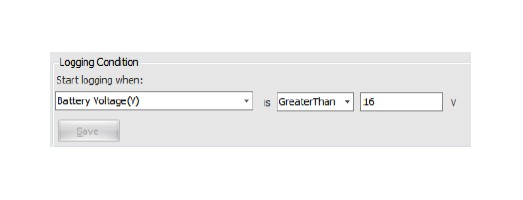
· All Analog, Digital, Frequency channels may be used as logging conditions
· Only Engine RPM and Vehicle Speed are available from GPS, AEMnet, or OBD-II
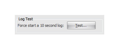
Log Test
· Temporarily forces the logger to begin logging and terminate after 10 seconds
· Useful for testing logger configuration
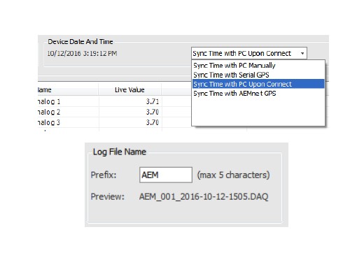
Device Date And Time
· Log files will be time stamped using this date/time
· AQ-1 date/time setting will reset if permanent 12V power is removed
· Select method by which AQ-1 date/time should be synced
Log File Name
· Log files will be named using the configurable prefix, file count, and date/time
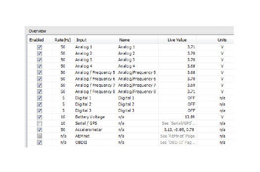
Input Overview
· Provides an overview of which channels are enabled for logging and other settings
· Enabled flag, logging rate, and name can be set for most channels
· Live channel reading can be viewed for most channels. Note: Permanent 12V must be present on main connector for proper operation
Configuration: Analog Inputs 1 - 4
The first four analog inputs are designed to accept and sample a 0-5V signal at up to 1000Hz. This signal may be scaled to engineering units and recorded in the data log for post-analysis. A software configurable pull-up resistor is provided for two-wire RTD sensors or similar.
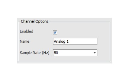
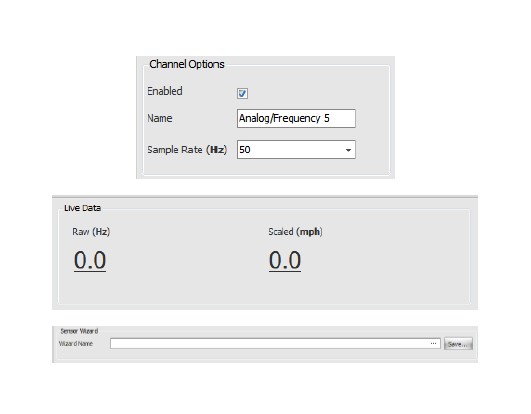
Channel Options
· Enabled checkbox determines if channel is logged or not
· Set the name that will appear in the data log
· Set the sampling rate of this input
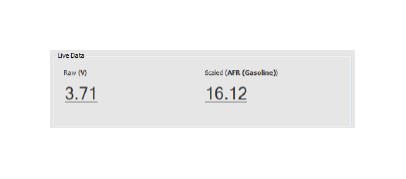
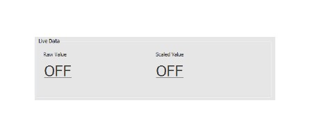
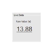
Live Data
· Displays the raw voltage measured at the input pin
· Displays the scaled value as will be recorded in the log
· AQ-1 requires 12V power at main connector for proper readings
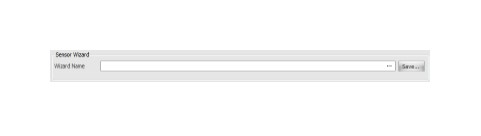
Sensor Wizard
· Load known sensor calibrations from Wizard database
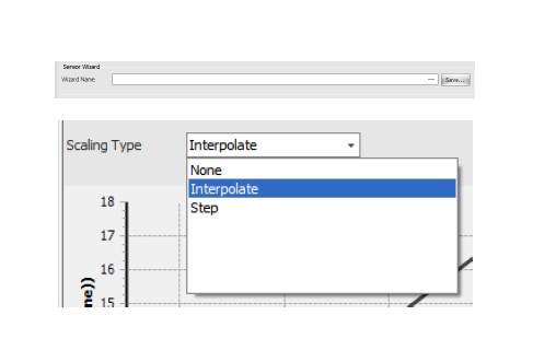
· Save custom sensor calibrations to Wizard database Scaling Type
· Scaling type is typically set to Interpolate. Step can be used for gear position sensors as an example
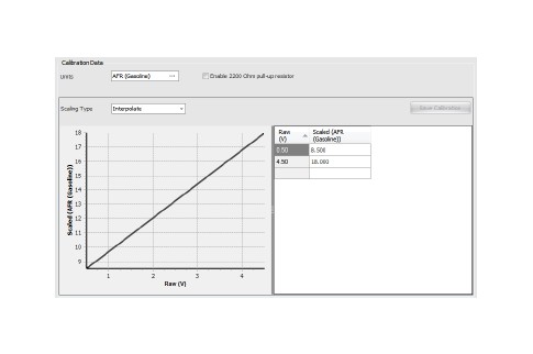
Calibration Data
· View/create sensor calibrations
· View/set the units of the scaled value to be recorded in the data log
· View/set the calibration points/curve
· The 2200 Ohm pull-up resistor is typically enabled for twowire RTD type sensors, unless that sensor is already connected to another logger/ECU device
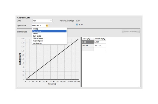
Configuration: Analog / Frequency Inputs 5 - 8
The second four analog/frequency inputs are designed to accept and sample a 0-5V signal or a 0-16V signal at up to 1000Hz. In addition, frequency and duty cycle type signals may be logged. This signal may be scaled to engineering units and recorded in the data log for post-analysis. There is no software configurable pull-up resistor available on this input type.
Please reference Configuration: Analog Inputs 1-4 Channel Options
· Enabled checkbox determines if channel is logged or
not
· Set the name that will appear in the data log
· Set the sampling rate of this input
· Frequency mode sampling is
Live Data
· Displays the raw voltage measured at the input pin
· Displays the scaled value as will be recorded in the log
· AQ-1 requires 12V power at main connector for proper readings
Sensor Wizard
· Load known sensor calibrations from Wizard database
· Save custom sensor calibrations to Wizard database
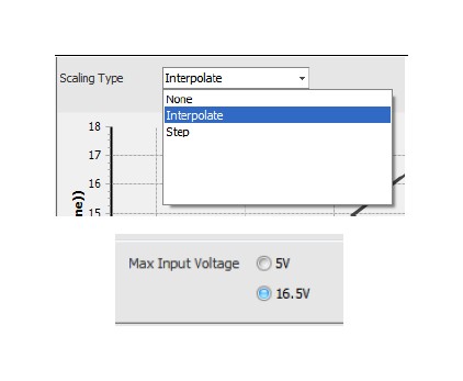
Scaling Type
· Scaling type is typically set to Interpolate. Step can be used for gear position sensors as an example
Max Input Voltage
· This setting should be configured to be higher than the maximum voltage expected from the sensor/ actuator being logged
Input Mode - Frequency
· Can be scaled further using the calibration table or left as raw Hertz
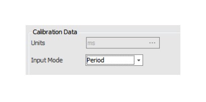
Input Mode - Period
· Logs the period of the sampled signal in milliseconds, no other scaling options are provided
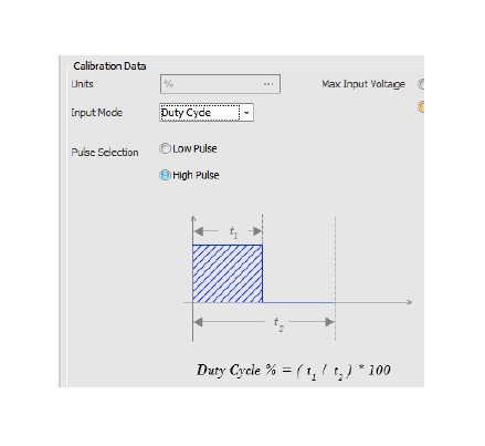
Input Mode - Duty Cycle
· Records the duty cycle (in percentage) of the incoming signal such as may be typical on a fuel injector
· The AQ-1 accommodates a typical 12V port injection fuel injector is without additional input circuitry/ conditioning
· Duty cycle percentage may be based off the high or low pulse of the signal
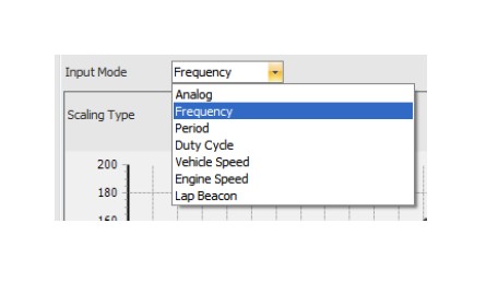
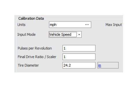
Input Mode - Vehicle Speed
· Intended for use with hall-effect style vehicle speed sensors such as are typically installed in a transmission
· SIGNAL MUST BE A CLEAN DC SQUARE WAVE OR DAMAGE TO THE LOGGER MAY OCCUR!!
· Set scaling options based on vehicle configuration
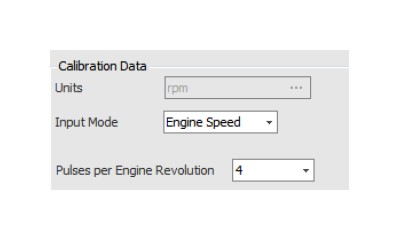
Input Mode - Engine Speed
· Intended to log a "tachometer style" output
· SIGNAL MUST BE A CLEAN DC SQUARE WAVE OR DAMAGE TO THE LOGGER MAY OCCUR!!
· The use of a tach adapter such as the MSD “Tach Signal GMR Pickup” Part Number #8918 is usually required when attempting to log engine rpm from high-voltage noisy sources
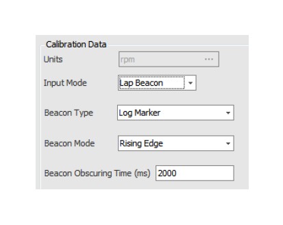
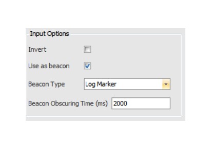
Input Mode - Lap Beacon
· Intended for use with a lap beacon receiver or similar · Inserts a generic, start/finish, or split marker into the log file. See the AEMdata manual for further information.
· Configure whether marker is inserted on rising or falling edge of lap beacon receiver output
· After a lap beacon is detected on the input, lap beacons will be ignored for the amount of time configured by Beacon Obscuring Time
Calibration Data
· View/create sensor calibrations
· Scaling type is typically set to Interpolate. Step can be used for gear position sensors as an example
· View/set the units of the scaled value to be recorded in the data log
· View/set the calibration points/curve
· The 2200 Ohm pull-up resistor is typically enabled for two-wire RTD type sensors, unless that sensor is already connected to another logger/ECU device
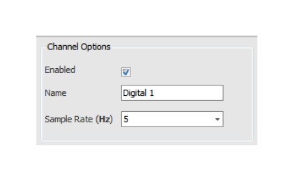
Configuration: Digital Inputs 1 - 3
Three digital inputs are available which are 12V tolerant and are considered 'ON' when a ground signal is applied to the input pin.
Channel Options
· Enabled checkbox determines if channel is logged or not
· Set the name that will appear in the data log
· Set the sampling rate of this input
Live Data
· Displays the raw level measured at the input pin
· Displays the scaled value as will be recorded in the log
· AQ-1 requires 12V power at main connector for proper readings
Sensor Wizard
· Load known sensor calibrations from Wizard database
· Save custom sensor calibrations to Wizard database
Input Options
· Choosing Invert will make an "OFF" at the pin to an "ON" in the data log and vice versa
· Digital inputs may be used as beacon inputs but with lower timing accuracy than Frequency Inputs which makes them more suitable for Log Markes than for lap timing
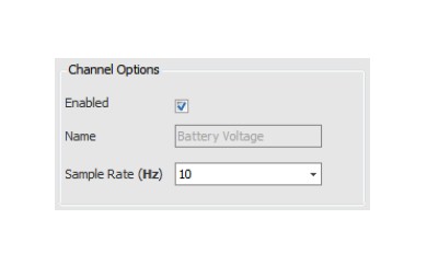
Configuration: Battery Voltage
This channel records the voltage that is applied Pin 1 - Switched 12V.
Channel Options
· Enabled checkbox determines if channel is logged or not
· The channel name is fixed at 'Battery Voltage'
· Set the sampling rate of this input
Live Data
· Displays the voltage level measured at the input pin
Configuration: Accelerometer
The internal 3-axis accelerometer ( /- 4g) requires a simple calibration procedure prior to use.
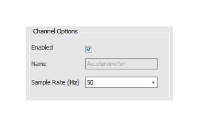
Channel Options
· Enabled checkbox determines if channel is logged or not
· The channel name(s) is fixed and will appear in the log as 'Accel Lateral', 'Accel Longitudinal', 'Accel Vertical'
· Set the sampling rate of this input
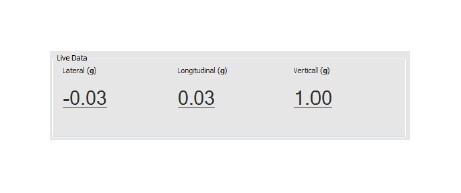
Live Data
· Perform calibration and ensure the AQ-1 is in the proper mounting position
· Displays the current acceleration measured by the logger including Earth's gravity (Vertical = 1g)
Accelerometer Calibration
· Click button and follow directions to calibrate and set mounting position
· This procedure must be performed to ensure proper accelerometer readings
Configuration: Serial/GPS
The serial input allows logging of an NMEA0183 Serial GPS or the serial telemetry output of an AEM Series I or Series II EMS.
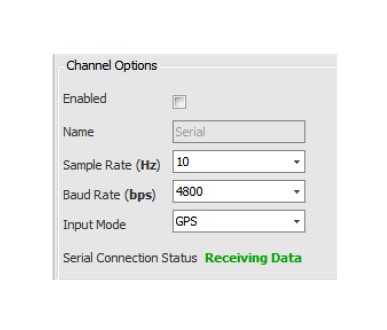
Channel Options
· Enabled checkbox determines if channel is logged or not
· Set the sampling rate of this input
· Refer to your GPS or EMS user manual to determine the appropriate baud rate setting
· Select 'GPS' or 'AEM EMS' input mode
Sensor Wizard
· Load known sensor calibrations from Wizard database
· Save custom sensor calibrations to Wizard database
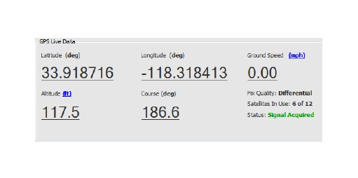
Live Data (GPS)
· GPS data will be displayed once a serial connection has been established and signal acquired
· The units for altitude and ground speed may be customized by clicking the unit hyperlinks
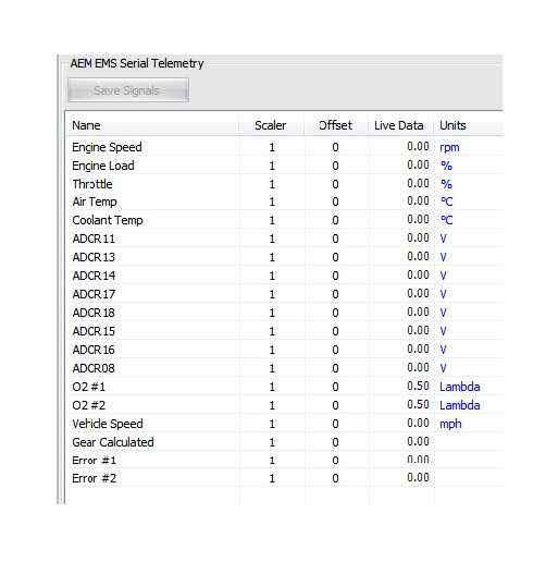
Live Data (EMS)
· EMS serial telemetry data will be displayed once a serial connection has been established
· Users may customize a scaler/offset to be applied to the values prior to being recorded in the data log which can be useful for ADCR channels
· The channel units may be customized by clicking the unit hyperlinks
Configuration: AEMnet
The AEMnet input provides "Plug and Play" functionality and allows logging for AEMnet devices.
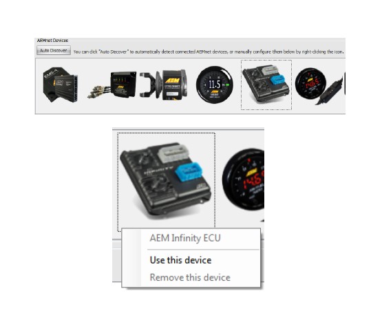
AEMnet Devices / Auto Discover
· Connect the AEMnet devices to the AQ-1 and ensure all devices are powered then click Auto Discover to configure the AQ-1 to log the connected devices
Add/Remove Device
· As an alternative to performing an Auto Discover, right-click the desired device icon and select 'Use this device' to configure it to be logged
· Devices may be removed by right-clicking its icon and selecting 'Remove this device'
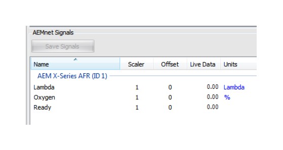
AEMnet Signals Live Data
· Live data will be displayed for configured and connected devices
· AQ-1 requires 12V power at main connector for proper readings
· Users may customize a scaler/offset to be applied to the values prior to being recorded in the data log
· The channel units may be customized by clicking the unit hyperlinks
Configuration: OBD-II PIDs
The AQ-1 has the capability of logging CAN-based OBD-II Parameter IDs (PID) found on 2008 and newer OBD-II compliant vehicles. It is possible that some manufacturers implemented CAN-based OBD-II earlier than 2008; check the vehicle's factory service information for more detail. OBD-II functionality is only mandated for vehicles with emission controls; electric vehicles, even if they have a similar looking diagnostic port, may not support OBD-II or the AQ-1.
The Society of Automotive Engineers (www.sae.org) and International Organization for Standardization (www.iso.org) have defined the standards and protocols that dictate how OBD-II works. Please reference the SAE publication J1979 for a list of all the possible PIDs. The PIDs are identifed by a hexadecimal number and can contain one or more signals related to the vehicle's systems and operation. Not all PIDs defined in J1979 are supported by every vehicle!!! The AQ-1 is capable of detecting which PIDs the vehicle manufacturer has implemented and will display them for selection as seen in the screenshots below.
Prerequisites
The AQ-1 must be properly wired into the vehicle's 12V system, including Pin 6 - Permanent Power, Pin 1 - Switched Ignition Power, and Ground, prior to plugging the OBD-II connector into the vehicle. The AQ-1 does not source anything but CANH/CANL from the OBD-II port. The vehicle's ignition key must be in the "ON" or "RUN" position such that the primary/engine ECU is turned on.
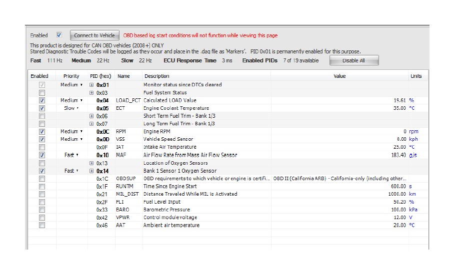
Configuring the AQ-1 to Log PIDs / Connect to Vehicle
Once the prerequisites have been satisfied, you must click the Connect to Vehicle button and wait while the logger queries the vehicle for the available PIDs; it is typical to see approximately 20-40 supported by the average vehicle.
· PID 0x01 is permanently enabled so that the logger can detect and record Stored DTCs while logging.
· Click the Enabled checkbox as desired to enable a PID to be logged.
· Choose a logging Priority to determine how fast (relatively) each PID is to be logged.
· Logging rate (in Hertz) varies with each vehicle's ECU Response Time, the number of Enabled PIDs, and their Priority.
Important Notes!
· Live Values will only update when NOT LOGGING
· You must press Connect to Vehicle once per session to be able to make configuration changes
· Only 0x0C Engine RPM, 0x0D Vehicle Speed, 0x11 Absolute Throttle Position are available to be used as a logging condition -- they must be present and Enabled!
· **Logging WILL NOT START while viewing the OBD-II PID Page!! Navigate to an alternative non-OBD page or disconnect from the AQ-1**
AQ-1 DATA LOGGER OBDII
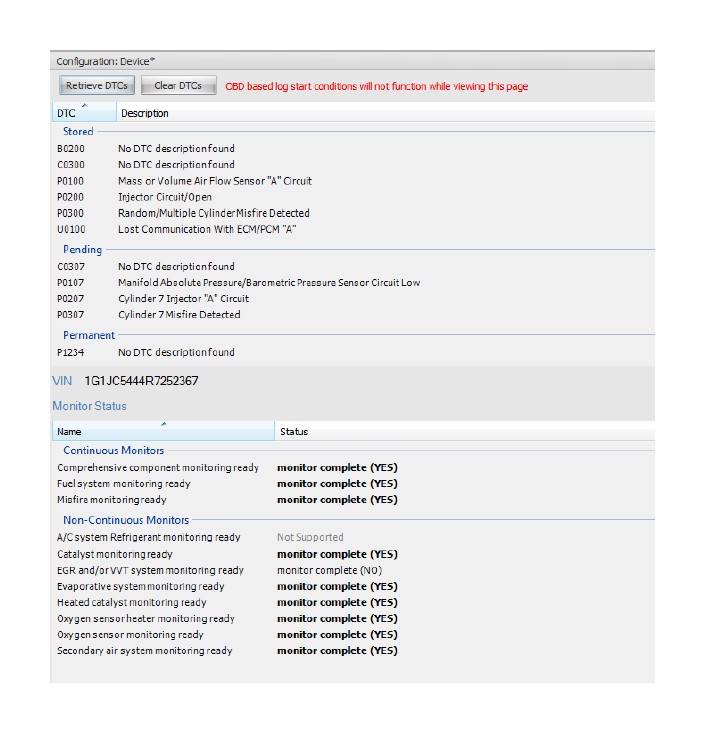
Configuration: OBD-II DTCs
The AQ-1 configuration software can retrieve and clear Pending, Stored, or Permanent Diagnostic Trouble Codes (DTC) from the primary/engine ECU as well as Continuous and Non-Continuous Monitor status.
Important Notes:
· Some vehicle manufacturers do not permit clearing of Permanent DTCs without specialized dealer-specific tools.
· Some DTCs may not be cleared while the engine is running.
· **Logging WILL NOT START while viewing the OBD-II DTC Page!! Navigate to an alternative non-OBD page or disconnect from the AQ-1**
· Manufacturer DTCs will be displayed but without description. Please reference the factory service manual for more information.
AQ-1 DATA LOGGER OBDII
DTC Logging
The OBD-II DTC page allows viewing and clearing of DTCs, however the AQ-1 is also capable of logging ("Stored" only) DTCs as they occur. Pending and Permanent codes will not be recorded in the data log. Only Stored codes from the primary/engine ECU will be recorded. When OBD-II PID logging is enabled (see OBD-II PIDs page), DTCs will be queried from the primary/engine ECU and placed in the data log as "Markers." Please reference the AEMdata help feature for information about Markers and how to view them; they will appear as vertical red lines in the time graph with details available by selecting the menu Data->Markers.
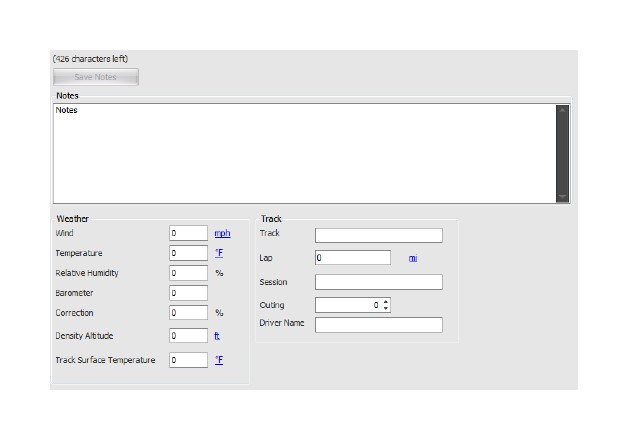
Configuration: Log Notes
Log notes are a way to record information about the conditions experienced while operating a vehicle and logging. This information will be stored in the data log and available for review in AEMdata by selecting the menu option View->Notes.
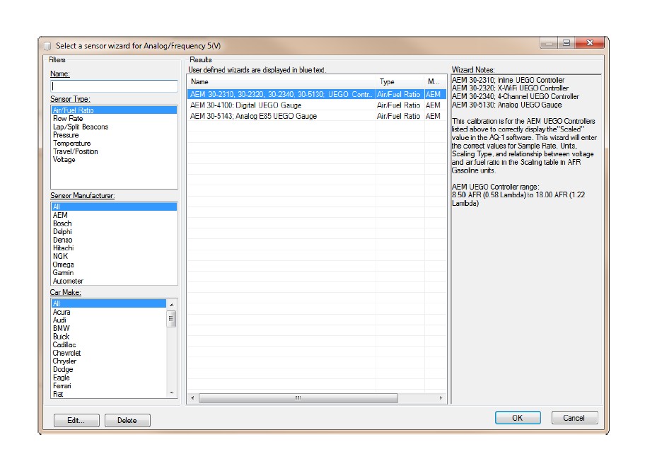
Configuration: Sensor Wizard
The Sensor Wizard is available on the majority of the input configuration pages to assist in configuration. It is essentially a database of sensor calibrations that AEM has compiled and made available for selection. The filters may be utilized to drill down to find the sensor you would like to connect to a particular input; selecting the desired sensor (or device) and clicking OK will apply the appropriate configuration to that AQ-1 input, simplifying the configuration process.
Log Files / SD Cards
The AQ-1 Data Logger includes a removable Secure Digital (SD) Card 2GB card that is located on the back of the logger. To remove the SD card, push the card in until a soft click is heard. The card will release and can be pulled out. To insert the card, push the card in until a soft click is heard. The card will remain locked in place.
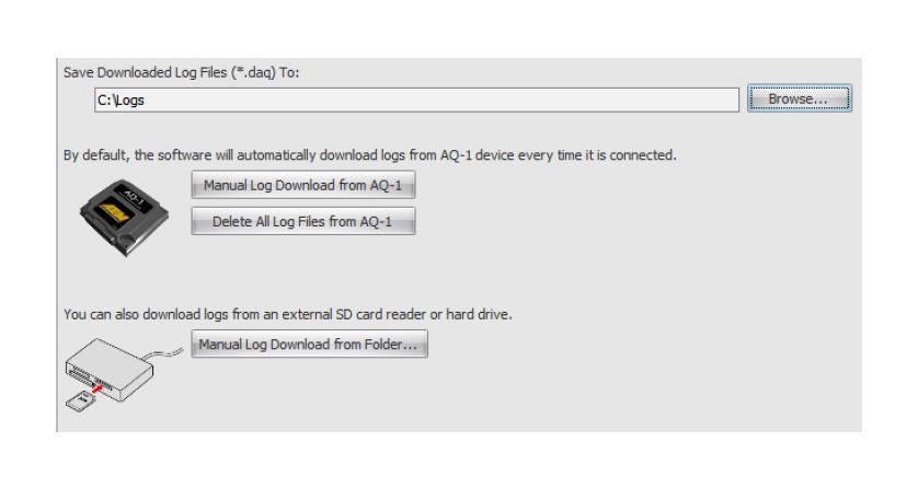
If any logs are present on the SD card, they will automatically be downloaded when the AQ-1 configuration software detects the logger through its USB connection. The following dialog will automatically open and download, convert, and copy the log file to the specified folder. The files then may be optionally opened in AEMdata for analysis. Please note that the files as recorded on the SD card are in a raw format (*.AQ1) which can not be opened in AEMData. The files must be specifically downloaded using the AQ-1 software to convert them for use with AEMdata. AEMData log files are in *.DAQ format.
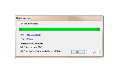
The "Save To" or destination folder for downloaded log files (*.DAQ) may be configured on the Log File page in the AQ-1 configuration software as seen below.
Occasionally, the SD card may require re-formatting. This can be accomplished by inserting the SD card into the AQ-1, connecting the AQ-1 to a PC via the USB cable, and using Windows Explorer to format the drive. FAT (or FAT16) is the recommended file system for the fastest performance; however, FAT32 is supported.
Device Information
The device information pane displays information about the connected AQ-1, the currently configured data rate, and SD card status. Remaining Log Time describes how much time is well
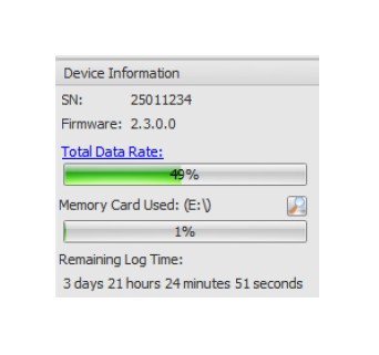
Total Data Rate
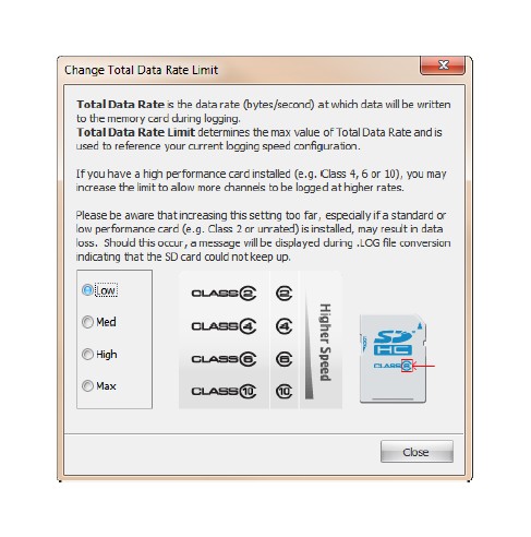
Total Data Rate is calculated based on the number of channels enabled for logging, the type of channel, and the logging rate selected. The maximum possible data rate is a function of the SD card type being used and by the design of the logger itself. The AQ1 Data Logger comes with a 2GB Class 2 SD card that is suitable for most cases. Clicking the blue 'Total Data Rate" hyperlink in the Device Information pane will open the following dialog. The purchase and use of third party high performance cards may allow higher total data rates as described below. A high data logging rate could cause a data loss if the data logging rate is set incorrectly. Secure Digital (SD) and Secure Digital High Capacity (SDHC) rated cards are compatible with the AQ-1. SDXC and beyond are not approved for use.
· SD/SDHC cards are rated as Class 2, Class 4, Class 6, or Class 10. The class can typically be identified by the Class number within a circle logo on the label of the card. Note: Class 2 cards commonly do not have the class number on the label. The AQ1 Data Logger comes with a 2GB Class 2 SD card that is suitable for most cases. Extremely high total logging rates may require use of a class 4, 6, or 10 SD/SDHC Card.
· Depending on the grade of the SD card, a high data logging rate could cause a data loss if the data logging rate is set incorrectly
FAQ / Troubleshooting
I just tried to download some logs and it says there are files with errors. This is caused be either:
a) Permanent 12V must be connected to Pin 6 and Switched 12V must be connected to Pin 1. Permanent 12V must remain constant to allow the logger to properly finish writing to the file after Switched 12V is removed. or, b) Logging conditions should be selected such that there is a clear transition to and from logging mode. For example 'Engine RPM > 350' would provide a clear transition from engine running (logging on) and engine off (logging off.) Selecting something like Engine RPM > 2000' will cause the logger to try and start and stop logging every time the engine transitions through 2000 RPM which could happen many times within a short duration of time.
The live values for a specific input don't update or stopped updating.
a) 12V is required to be on on both Pin 6 and Pin 1 for live values to read properly. USB power alone is not sufficient.
b) Live value readouts will slow down or stop altogether when logging is active. Confirm whether logging is active by referring to the status bar in the lower left hand corner of the screen.
I followed the procedure to Connect to Vehicle and query for supported PIDs but I don't see the one I'm looking for.
The AQ-1 OBD-II logger supports all the OBD-II PIDs defined in SAE Publication J1979DA_201110. Manufacturer specific PIDs, other vehicle specific CAN data is outside the scope of this product. Not all PIDs defined in J1979 are supported by every vehicle!!! It is up to the manufacturer's discretion as to which PIDs are implemented. The AQ-1 is capable of detecting which PIDs are available and will display them for selection as seen in the screenshots below.
My car is newer than 2008 but I can't read any OBD data.
Ensure that the AQ-1 is wired properly and the connector is firmly seated into the vehicle's OBD connector. The AQ-1 has the capability of logging CAN-based OBD-II Parameter IDs (PID) found on 2008 and newer OBD-II compliant vehicles. It is possible that some manufacturers implemented CAN-based OBD-II earlier than 2008; check the vehicle's factory service information for more detail. OBD-II functionality is only mandated for vehicles with emission controls; electric vehicles, even if they have a similar looking diagnostic port, may not support OBD-II or the AQ-1.
It says I have Diagnostic Trouble Codes (DTC) but it won't clear or log them.
The OBD-II DTC page allows viewing and clearing of DTCs, however the AQ-1 is also capable of logging ("Stored" only) DTCs as they occur. Pending and Permanent codes will not be recorded in the data log. Only Stored codes from the primary/engine ECU will be recorded. When OBD-II PID logging is enabled (see OBD-II PIDs page), DTCs will be queried from the primary/engine ECU and placed in the data log as "Markers." Please reference the AEMdata help feature for information about Markers and how to view them; they will appear as vertical red lines in the time graph with details available by selecting the menu Data->Markers.
Can I see PIDs or DTCs from all the ECUs in my vehicle?
No, the AQ-1 only supports communication with the primary/engine ECU.
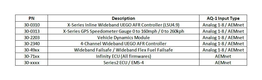
Is the AQ-1 compatible with the 30-0333/30-0334 X-SeriesWideband UEGO with OBD Integration?
No, the 30-0333/30-0334 is not an AEMnet compatible device and functions by simulating a secondary/tertiary ECU in the vehicle. The AQ-1 is only OBD compatible with the primary/engine ECU. Please use 30-0300 or 30-0310 X-Series Wideband products over AEMnet for use with the AQ-1.
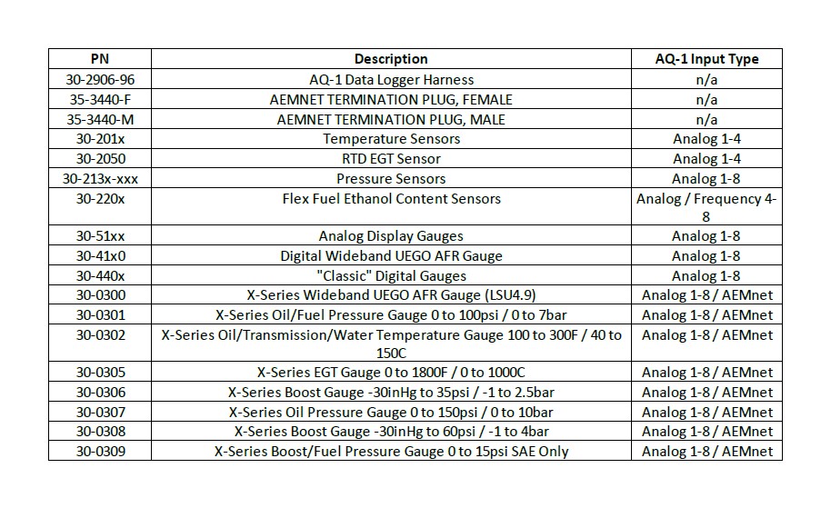
Compatible AEM Products
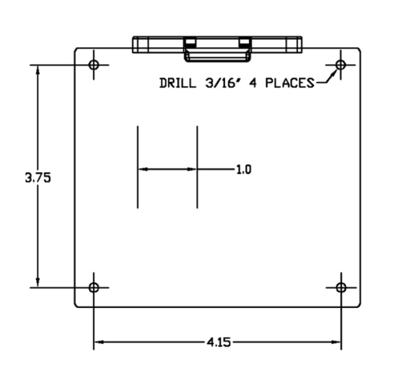
Mounting Drill Template
A drill template is provided to aid in determining mounting hole locations when mounting the AQ1 Data Logger. Before drilling any holes, make sure the drill template is printed to the proper size. The two vertical lines on the drill template are spaced one inch apart when the drill template is printed to the proper size. Verify the two vertical lines are one inch apart on the printed drill template. Due to variances in printers, the print size may need to be adjusted if the two vertical lines are not one inch apart.
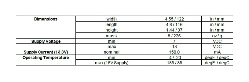
Specifications