 FREE 1 to 3-Day Delivery on Orders $119+ Details
Best Sellers


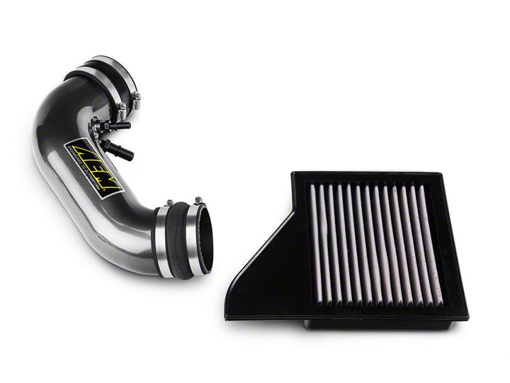
How to Install AEM Intake Tube & Dryflow Air Filter Kit (11-14 GT) on your Ford Mustang
Installation Time
1 hours
Tools Required
- Pair of Diagonal Cutters or Tin Snip Pliers (something to cut thick wire)
- Medium Size Flat Head Screwdriver
- Old Towel
- 5/8 Wrench
- 3/4 Wrench
Shop Parts in this Guide
Special Notes
1) **The installation instructions from AEM state to take off the Strut tower Brace as well as fully remove the plastic engine cover. For my instructions I am not removing these components as I feel they are not necessary and reduce time of installation as well as reduce tools needed. I instead used a towel to protect engine cover from scratching against tower brace.
2) This particular installation is for a 2013 ford Mustang GT 5.0 Liter V8, however these instructions will also work for 2011 through 2014 models of Mustang GT.
3) A carb Sticker was installed during this installation as this device is intended for legal use in states using CARB emissions standards and the installation was done in California, however this may not be necessary in your state. Please check your local and state laws for adherence to these emissions standards.
4) Question and answer section of American Muscle web site for this part states that the sound tube is retained during the install:
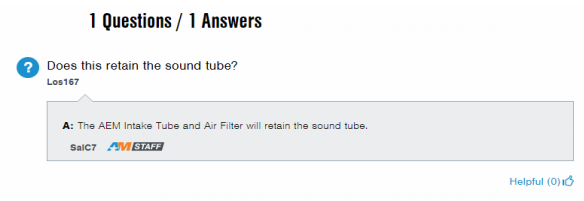
This is FALSE and the AEM instructions state that the SOUND TUBE IS REMOVED.
Ensure all parts are included, notice A,B,C etc. on diagram below and match with parts in the list. You should have all these parts in the box.
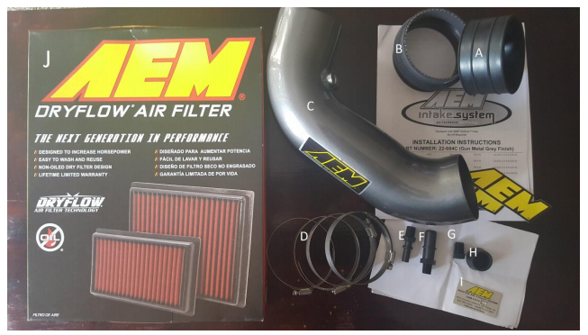
A: 1 Plastic Rubber Ribbed Coupler
B: 1 Vulcanized Rubber Coupling
C: 1 AEM Aluminum Intake Tube
D: 4 Band Clamps
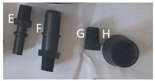
E: 1 Small Plastic Hose Connector
F: 1 Large Plastic Hose Connector
G: 1 Plastic Hose connector plug
H: 1 Sound Tube Plug
I: 1 CARB Sticker (Optional for those not living in states with CARB emissions standards)
J: 1 AEM Dry Flow Air Filter
Installation Instructions
1) Car should be turned off with engine cool. Park vehicle on flat surface and engage emergency parking brake and put transmission in gear. If your car is automatic, engage parking brake and put car in park.
2) Open hood and Secure.
3) Disconnect Battery.
4) Remove Stock Intake Tube and Sound Tube:
a) Get access to Ring Clamp around throttle body under engine cover. The AEM instructions state to take off the strut tower brace and then remove the engine cover, however this is not necessary. Be careful as you can scratch your engine cover against the tower brace, I was just careful however you can wrap a towel around your engine cover or tower brace. Basically just put something soft between the engine cover and tower brace. Remember to keep your stock parts!
b) Simply disengage cover from three points where the cover connects. First disengage the front by gently pulling up the cover:
c) Then disengage the cover from the back passenger side, once again pulling straight up.
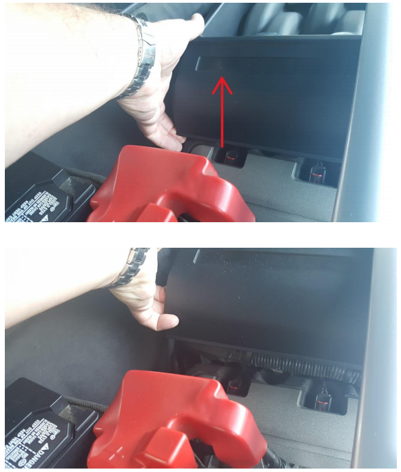
d) Then disengage the cover from the back driver side of the cover, once again pulling straight up.
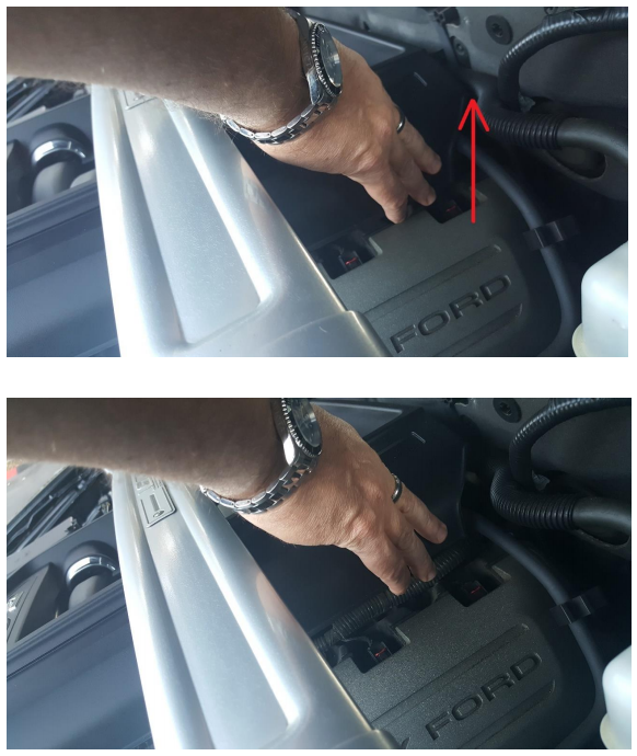
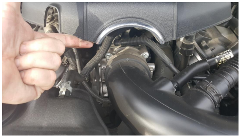
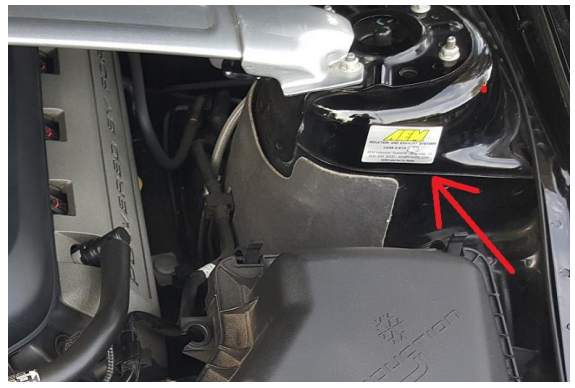
e) Now the engine cover will be loose and you can move it left to the side and out of the way. Be careful as you can scratch your engine cover against the tower brace. Use the Towel to cover the engine cover or wrap tower brace to keep parts from scratching against each other. The red Arrow is pointing to the screw you are trying to get to:
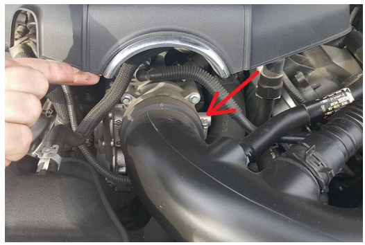
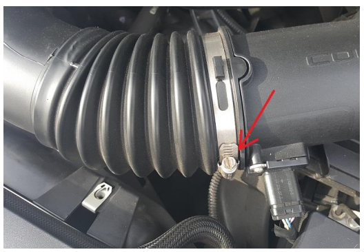
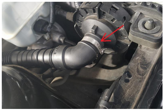
f) Remove the band clamp using a Flathead Screwdriver.
g) Next remove band clamp on other end of the intake tube using flathead screwdriver:
h) Now we need to cut the band clamp at the end of the sound tube before the sound baffle. Please note that the AEM instructions have you disconnect sound tube from Intake tube, However I left this connected and removed the entire apparatus sound tube and intake tube all as one piece.
i) Remove Sound Tube and Cover the Connection with the AEM Sound tube Cap.
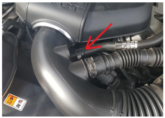
j) Remove the breather hose connected to the intake tube. This can be easily done by sliding grey tab out of the slot on the coupling. This is the hose you need to disconnect. On automatic cars there will be an additional vent line to disconnect.
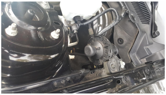
k) Remove the intake tube and sound tube as one unit. You can now access the throttle body. Now is a good time to maybe use some throttle body cleaner and clean out the throttle body as well as clean any areas you usually cannot access.
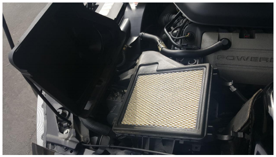
5. Remove Stock Airbox Filter and replace with AEM Dry Filter
a) Release the two clips folding the filter compartment. They should unclip easily without tools required.
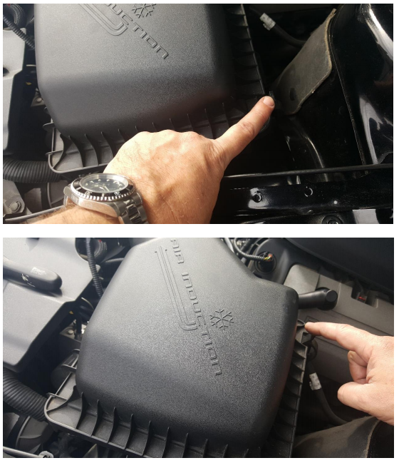
b) Open the filter compartment to expose the air filter and remove. Now is a good time to clean out the air box of any leaves or debris.
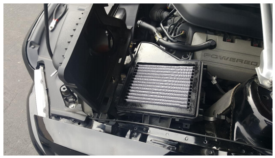
c) Once the Filter compartment is clean, install the AEM Dry Air Filter. Be sure all four corners are secured and the filter is snug and sealed to the filter compartment. Close the air filter box cover and re-clip the two clips holding the air filter box cover back on and make sure they are securely fastened.
6. Install AEM Aluminum Intake Tube.
Before installing Intake tube connect the plastic hose connectors in to the aluminum Intake Tube BEFORE installing Tube. If you skip this step the connections can still be installed however it is WAY EASIER if you do this ahead of install of the tube. All connectors should be installed hand tight then ¼ turn with a wrench.
PLASE NOTE THAT THE CONNECTORS FOR THE HOSES DIFFER BETWEEN AUTOMATIC AND MANUAL TRANSMISSION.
THESE INSTRUCTIONS COVER INSTALLATION OF AN AUTOMATIC TRANSMISSION, HOWEVER, THIS INSTALL AND PICTURES SHOWN HERE IN THESE INSTRUCTIONS ARE FOR MANUAL TRANSMISSION ONLY!
Manual Transmission Connection Instructions:
Using diagram at beginning of instructions, we will be using parts F and G ONLY. PART E IS NOT USED
Install part F into Aluminum intake tube on the TOP port. Meaning when the tube is installed in the vehicle, part F will be in the TOP port.
Install part G into to Aluminum intake tube on the BOTTOM port. Meaning when the tube is installed in the vehicle, part G will be in the BOTTOM port.
Automatic Transmission Connection Instructions:
Using diagram at beginning of instructions, we will be using parts E and F ONLY. PART G IS NOT USED:
Install part F into to Aluminum intake tube on the TOP port. Meaning when the tube is installed in the vehicle, part F will be in the TOP port.
Install part E into to Aluminum intake tube on the BOTTOM port. Meaning when the tube is installed in the vehicle, part E will be in the BOTTOM port.
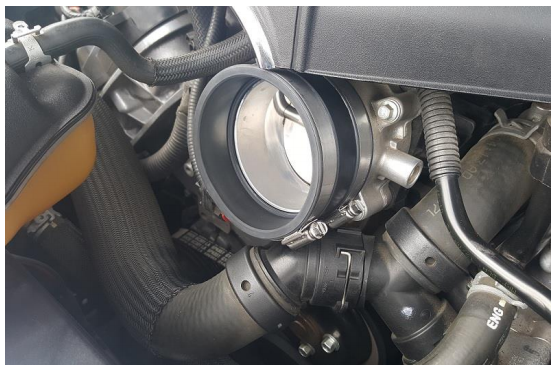
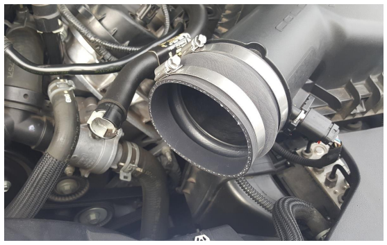
a) Once the Plastic connectors for Hoses are installed we can start installation of the Intake Tube. Install 2 Ring Clamps around the Plastic/rubber Grooved Coupler and then install the coupler with the rings around the throttle body intake as shown below.
b) Install the other 2 Ring Clamps around the Vulcanized Rubber Coupler and then install the coupler with the rings around the tube coming from Air Box as shown below.
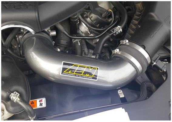
c) Gently install the AEM Aluminum intake tube being careful not to scratch it since it is anodized aluminum. Tighten down the 2 clap rings on both ends of the intake tube until snug, not super tight using the flathead screwdriver. Do not overtighten as this can damage the Air box, Throttle Body or Aluminum Intake Tube or possibly break the clamps.
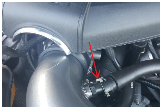
d) Attach the last hose to the plastic Connector on the Intake tube:
e) FOR AUTOMATICS ONLY: Attach Second Hose to Intake Tube. (picture not shown)
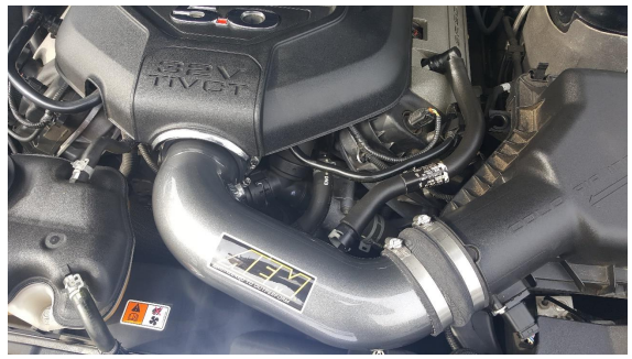
f) Reseat the engine cover:
g) CARB Sticker install (required for cars in states conforming to CARB emissions standards.
Installation Instructions Written by AmericanMuscle Customer on 1/2/18.
