 FREE 1 to 3-Day Delivery on Orders $119+ Details
Best Sellers


How to Install Aeromotive High Flow Fuel Rail Kit (96-98 Cobra) on your Ford Mustang
Shop Parts in this Guide
CAUTION:
Installation of this product requires detailed knowledge of automotive systems and repair procedures. We recommend that this installation be carried out by a qualified automotive technician.
Installation of this product requires handling of gasoline. Ensure you are working in a well ventilated area with an approved fire extinguisher nearby. Extinguish all open flames, prohibit smoking and eliminate all sources of ignition in the area of the vehicle before proceeding with the installation.
When installing this product, wear eye goggles and other safety apparel as needed to protect yourself from debris and sprayed gasoline.
WARNING!
The fuel system is under pressure. Do not open the fuel system until the pressure has been relieved. Refer to the appropriate vehicle service manual for the procedure and precautions for relieving the fuel system pressure.
The enclosed Aeromotive fuel rails utilize o-ring sealed AN-08 style ports; these ports are NOT PIPE THREAD and utilize NO THREAD SEALANT. To use the enclosed fuel rails in your vehicle’s fuel system you must install the necessary adapter fittings and o-rings, high pressure fuel lines and regulator to adapt your system to the configuration and ports of these fuel rails. Please call for a catalog of the complete line of quality Aeromotive products.
The enclosed Aeromotive fuel rails are intended to be installed on an unmodified OEM intake manifold of the identified application. Aeromotive cannot guarantee the proper fitment on aftermarket intake manifolds and the end user is responsible for verifying proper fitment and assumes all liability.
When installing o-rings it is important to place a small amount of light oil on both the o-ring and the mating surface to ease installation and prevent damaging the o-ring.
The following installation instructions are for a typical installation, for specific year and model installation instructions please refer to your vehicles service manual.
Aeromotive system components are not legal for sale or use on emission controlled motor vehicles.
Supplies needed:
Vehicle service manual
Fuel injector replacement O-rings
Light oil
Solvent parts cleaner
Clean shop towels
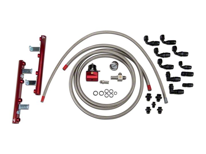
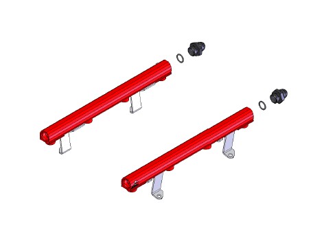
This kit contains the following parts:
1ea p/n 14104 Ford 4.6L DOHC Fuel Rails
1ea p/n 15102 Supply Adapter Tee Fitting
1ea p/n 15101 Return Adapter Fitting
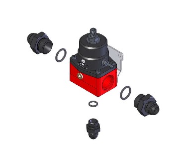
1ea p/n 13101 A1000 Injected Bypass Regulator
2ea p/n 15607 –8/-8AN Cutoff Tapered Flare Fitting
2ea p/n 15610 –10/-8AN Cutoff Tapered Flare Fitting
1ea p/n 15606 –6/-6AN Cutoff Tapered Flare Fitting
1ea p/n 15650 –6 Straight Hose End
1ea p/n 15652 –6 90-Deg Hose End
1ea p/n 15653 –8 Straight Hose End
5ea p/n 15655 -8 90-Deg Hose End
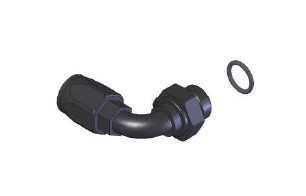
2ea p/n 15665 –8 90-Deg Male ORB Hose End
3ft –6 Stainless Steel Braided Fuel Line
12ft –8 Stainless Steel Braided Fuel Line
1ea AN-06 O-Ring
4ea AN-08 O-Ring
2ea AN-10 O-Ring
The following steps are typical of most installations:
1. Once the engine has been allowed to cool, disconnect the negative battery cable and relieve fuel system pressure, referring to the appropriate vehicle service manual for the procedure on doing so.
2. Remove the air intake ducting.
3. Check for any dirt or debris around the fuel injectors. If any is evident, wash it off with some solvent parts cleaner or wipe it off with a clean shop towel.
4. Disconnect the electrical connector at each injector, making note of the location of each.
5. Disconnect both the supply and return fuel lines from the OEM fuel rails. These lines are attached by a special quick disconnect fitting which requires a special tool for removal. Place clean shop towels around the open fuel lines to catch any gasoline that may drip out and to prevent any dirt from entering the fuel lines. Failure to satisfy all safety considerations will result in fire, explosion, injury and/or loss of life to yourself and/or others.
6. Label and disconnect any electrical wiring, vacuum lines and throttle body components that will interfere with the fuel rail removal and installation.
7. Remove the 4 mounting bolts that attach the fuel rail to the intake manifold.
8. Place clean shop towels around the injectors to catch any gasoline that may be spilled during their removal. Remove the injectors from the manifold by gently pulling upward on the fuel rail / injector assembly. Keep all injectors connected to the fuel rails. If an injector does pull out of the fuel rail, it may spill a large amount of gasoline.
Failure to satisfy all safety considerations will result in fire, explosion, injury and/or loss of life to yourself and/or others.
9. Carefully remove the fuel injectors from the OEM fuel rail.
10. Remove the old o-rings from the fuel injectors, inspect the injectors for any dirt or debris and clean if needed. It is suggested that the old o-rings be replaced, contact your local parts store or dealer to purchase the correct replacement o-rings.
11. Carefully install the new injector o-rings on the injectors. When installing o-rings it is important to place a small amount of light oil on both the o-ring and the mating surface to ease installation and prevent damaging the o-ring.
12. Place a thin coat of light oil in the fuel rail injector bores and in the lower intake manifold injector bores to help prevent cutting the o-rings during installation.
13. Carefully place each of the fuel injectors in the corresponding fuel injector bore of the Aeromotive fuel rails.
14. Place each of the fuel rail / injector assemblies onto the lower intake manifold, ease the fuel injectors into the injector bores in the lower intake being careful that the injector does not dislodge itself from the fuel rail.
15. Reinstall the rail mounting bolts and tighten.
16. With the Aeromotive fuel rail properly secured to the intake manifold, Move the fuel injector vertically downward until it bottoms out on the intake manifold, In this downward position, inspect the upper fuel injector o-ring (on the fuel rail side) and insure it is fully covered by the fuel rail injector bore. If any of the o-ring is exposed, loosen the fuel rail bracket screws and adjust the installation height unit the oring is no longer exposed and retighten the bracket screws. In the situation where the fuel injector has no vertical travel, either the fuel rail brackets can be adjusted or the brackets shimmed until the fuel injector fits freely. Do not pressurize the fuel rail until the proper fuel rail installation height is achieved.
17. Find suitable place in the vehicle’s engine compartment to mount the Aeromotive regulator, typically on the passenger side strut tower. Using the supplied mounting bracket as a template, mark the bracket mounting holes and drill to accept a #10 screw.
18. With the bracket attached to the regulator, mount the bracket and regulator to the vehicle using two #10 screws, nuts and lock washers.
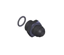
19. Install one AN-10 o-ring on the port (cut-off) side of each of the two p/n 15610 ORB-10/AN-08 port fittings, and one o-ring on the p/n 15606 ORB-06/AN-06 port fitting. Thread the port side of the p/n 15610, with the o-ring, into each of the two AN-10 side ports on the regulator. Also thread the port side of p/n 15606 port fitting into the bottom of the regulator.
20. Install one ORB-08 o-ring on each of the two p/n 15607 ORB-08/AN-08 cutoff tapered flare fittings.
21. Install one ORB-08 o-ring on each of the two AN-08/ORB-08 90-degree male hose ends.
22. Thread the port (o-ring) side of each 15607 port fitting in the back of each fuel rail.
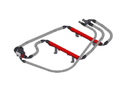
23. Inspect the OEM fuel supply line o-rings and replace if necessary. Place a light coat of oil on the fuel supply line o-rings and the supply line adapter fitting to ease installation. Connect the p/n 15102 Spring Lock to AN-08 tee adapter fitting onto the OEM fuel supply line.
24. Connect one AN-08 90-degree male ORB hose end to the front of each fuel rail. Plan a route for each of the two lines between the p/n 15102 fuel supply tee adapter and the fuel rails. Measure the two lengths of fuel line needed. See section titled Hose and Fitting Assembly for fuel line assembly instructions. Once the hoses are assembled, ensure there is no debris in the hose and install them.
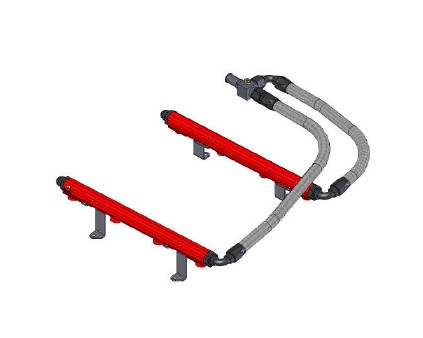
25. Connect one AN-08 90-Degree hose end to the rear of each fuel rail. Plan a route for each of the two lines between the fuel pressure regulator and the fuel rails, measure the two lengths of fuel line needed. See section titled Hose and Fitting Assembly for fuel line assembly instructions. Once the hoses are assembled, ensure there is no debris in the hose and install them.
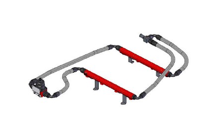
26. Inspect the o-rings on the OEM quick disconnect fitting and replace if necessary. Coat o-rings and the adapter fitting with a light oil and install the p/n 15101 Spring Lock to AN-06 Ford quick disconnect adapter fitting on the OEM return fuel line.
Please note if installing a high performance fuel pump, (Similar to Aeromotive P/N 11101) the OEM return line will be too restrictive to handle the volume of fuel that these pumps are capable of pumping. To prevent loosing lower pressure adjustability of your regulator it will be necessary to replace the OEM return line with a 3/8” ID (AN-06) return line in these cases.
27. This kit contains one AN-06 straight hose end which will connect to the OEM fuel line adapter fitting and one AN-06 90 degree hose end, to connect to the AN-06 union on the bottom of the fuel pressure regulator. With these fittings in place, measure the length of fuel line needed. See section titled Hose and Fitting Assembly for fuel line assembly instructions. Once the hose is assembled, ensure there is no debris in the hose and install it.
28. Reassemble the vehicle using the reverse of the foregoing removal procedure.
29. Remove the 1/8 NPT pipe plug from the fuel supply adapter tee fitting and attach a suitable fuel pressure gauge if desired.
Ensure that any spilled gasoline and any gasoline soaked shop towels are cleaned up and removed from the vicinity of the vehicle!
30. Reconnect the battery and turn the ignition to the ON position WITHOUT starting the car. After several seconds, check the fuel pressure. If there is no fuel pressure, turn the ignition key to the OFF position, wait one minute, return the ignition to the ON position, and recheck the fuel pressure. Repeat this ignition OFF and ON procedure until the fuel pressure gauge registers fuel pressure.
With the fuel pressure gauge registering fuel system pressure, check for fuel leaks from and around the Aeromotive fuel pressure sensor adapter, fuel rails, all fuel lines and connections! If any fuel leaks are found, turn the ignition key to the OFF position, remove any spilled fuel and repair the leak before proceeding!
31. Once the fuel pressure gauge registers fuel system pressure and there are no fuel leaks, start the engine and adjust the regulator to the desired fuel pressure.
32. Once the desired fuel pressure is achieved, tighten the regulator adjustment jam nut and attach the vacuum line.
33. Turn off the engine and allow it to cool. If you do not want to keep the fuel pressure gauge on the vehicle, relieve the fuel system pressure as instructed in the appropriate vehicle service manual. Remove the fuel pressure gauge and reinstall the 1/8 NPT pipe plug, using thread sealant.
34. Test drive the car to insure proper operation and re-check the fuel system for leaks. If any leaks are found, immediately shutoff the engine and repair the leak(s)!
Hose and Fitting Assembly
CAUTION:
When assembling this product, wear eye goggles and other safety apparel as needed to protect yourself from debris and sharp edges.
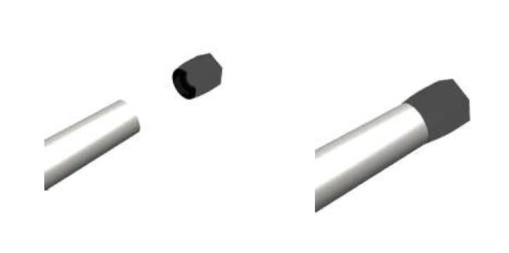
A. Wrap hose with masking tape at desired cutoff length. Cut hose through masking tape squarely to desired length using a cut-off machine or a fine tooth hacksaw. Remove the masking tape.
B. Unthread the hose socket from the rest of the hose end fitting.
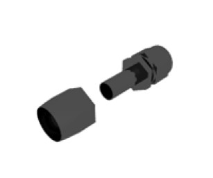
C. Insert hose in the socket with a twisting and pushing motion until the hose is fully seated in the socket.
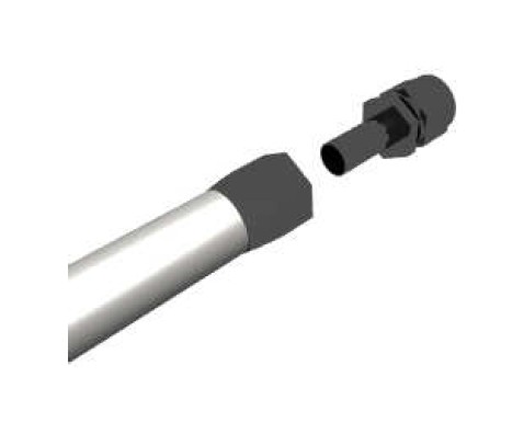
D. Using a grease pencil, marker or tape, mark the location of the hose in relation to the hose socket which you just installed.
E. Using a light oil lubricate the inside of the hose and the hose end mating parts.
F. Carefully thread the hose end onto the hose socket, making sure that the hose does not push out of socket, by observing the mark you placed on the hose in step D.
G. Using a properly sized wrench, complete threading the two components together (The maximum allowable gap between the two fitting components is .030 inches).
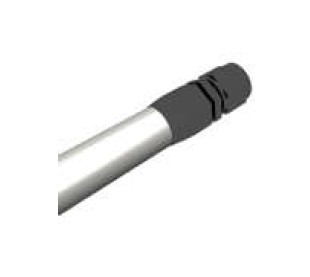
H. Inspect the hose for push out by comparing the mark you made on the hose in step D to the hose end socket location.
I. Clean all debris from exterior and interior of hose.
J. All lines should be tested to twice their operation pressure prior to use.
