 FREE 1 to 3-Day Delivery on Orders $119+ Details
Best Sellers


How to Install a BBK High Flow Aluminum Fuel Rail Kit on your 1996-1998 Mustang GT
Installation Time
3 hours
Tools Required
- 1/2”& 5/8” Spring-Lok type Fuel Line Disconnect Tools
- 11/16" Wrench
- 12mm, 10mm, and 8mm Sockets
- 5mm and 5/32" Allen Wrenches
- Lithium Grease
- Teflon Tape
- Anti-Seize
Shop Parts in this Guide
NOTE- 1998 Mustang will require the purchase of (1) BBK 1707 or equivalent fuel pressure regulator.
Warning!
Fuel system is under pressure. You will need to relieve this pressure in Step 4. Please read instructions carefully!
Tools required-
1/2”& 5/8” Spring-Lok type fuel line disconnect tools, 11/16” wrench, 12, 10, & 8mm sockets, 5mm & 5/32” Allen wrenches. Lithium grease, Teflon tape, Anti seize.
Step 1
Disconnect negative battery terminal.
Step 2
Remove air inlet hose assembly from the throttle body.
NOTE
The throttle body does not need to be separated from the plenum for the next step. You can remove them together as one piece.
Step 3
Disconnect the throttle cables, unplug the sensors and vacuum connections from the intake plenum (also known as the intake elbow), unbolt the EGR valve from the driver side and unbolt and remove the intake plenum assembly.
NOTE
In the next step you will release the fuel pressure in the fuel rails. Be sure to extinguish any open flames and disable any spark or ignition sources, or other potential fire hazards around the work area.
Keep in mind that Gasoline vapors are more flammable than gasoline itself.
Step 4
Hold a rag around the shrader valve on the front of the passenger side rail, and then bleed off any fuel pressure by depressing the valve with a small screwdriver or pick tool.
Step 5
Unplug the electrical connections from the fuel injectors and fuel pressure sensor (99-04).
Step 6
Using 1/2” and 5/8” Spring Lok removal tools, disconnect fuel feed and return lines from the fuel rails.
Step 7
Use an 8mm socket to remove the studs that attach the fuel rails to the intake manifold.
Step 8
Remove the fuel rails and injectors.
NOTE
Now is the time to inspect your fuel injector tips and O-rings. If they are damaged, replace them. Damaged O-rings can cause a fuel leak.
Step 9
Apply a touch of white grease to all of the supplied O-rings and to the O-rings on the fuel injectors.
Step 10
Place (1) O-ring over the ends of the (2) rail end caps, the (2) rail end adapters, and the (1) 5/8” Spring Lok fitting. The remaining O-ring is a spare since the O-rings are thin and delicate BBK has supplied (1) extra.
Step 11
For both rails, install an end cap on the front of the rail and a -6 rail end adapter on the rear of each rail and attach the rail mounting tabs with the supplied 1/4”-20 bolts.
NOTE
Each rail mounting tab has a round hole and a slotted hole. The round holes will attach the rails. The slotted holes will attach to the intake manifold.
Step 12
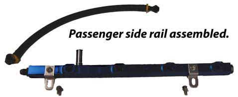
Install supplied Spring Lok fitting into the side of the passenger rail.
Step 13
Insert (4) injectors into the passenger side rail.
Step 14
Install passenger side rail and injectors by guiding the tip of each injector into its respective bung in the intake manifold. Secure the rail to the intake manifold using (2) supplied clamps and (2) 6mm bolts.
Step 15
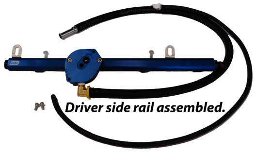
Thread the supplied 90° barbed brass fitting into the adapter base. When the adapter base is installed onto the driver side rail the barbs needs to point towards the firewall. (This is the return line.) Now push one end of the supplied 30” 3/8” hose onto the 90° fitting. Push the supplied Spring Lok adapter into the other end of the 30” 3/8” hose.
NOTE
Take extreme care when installing the small socket cap into the fuel rail. Inattention could cause cross threading of screws.
Step 16
Install adapter base to driver side rail with supplied O-ring using the supplied 6-32 SHCS’s
Step 17
Insert (4) injectors into the driver side rail.
Step 18
Install driver side rail and injectors by guiding the tip of each injector into its respective bung in the intake manifold. Secure the rail to the intake manifold using (2) supplied clamps and (2) 6mm bolts.
Step 19
Route the 30” 3/8” hose around back of the intake manifold to meet up with the stock fuel line on passenger side of car and connect to stock return line.
Step 20
96-97
Remove the stock fuel pressure regulator from the passenger side rail or purchase a BBK 1707 or equivalent fuel pressure regulator and install onto the adapter base using the supplied hardware and base gasket.
OR
1998
Purchase a BBK 1707 or equivalent fuel pressure regulator and install onto the adapter base using the supplied hardware and base gasket.
Step 21
Connect the supplied 30” 5/32” vacuum hose to the fuel pressure regulator and route it around the back of the intake manifold to connect to the stock vacuum line (passenger side) using the supplied plastic double ended hose barb
Step 22
Assemble the crossover hose by pushing the barbed ends of the supplied 90° - 6 fittings into the ends of the hose.
Step 23
Tighten the crossover hose onto the threads of the rail end adapters on the back of both rails.
NOTE
When routing the crossover hose, be mindful of hot EGR tube it must pass by. Route so no contact is made with the EGR tube.
Step 24
Route the stock fuel feed line under A/C line and connect to the 5/8” Spring Lok fitting on the side of the passenger rail.
Step 25
Reconnect the negative battery terminal.
Step 26
Without starting the engine-Turn the ignition key to the ON position, then OFF 3 times and return to the ON position. Check all connections for fuel leaks. Correct any leaks before starting the engine.
Step 27
Re-install the intake elbow and re-attach all connections.
Step 28
Re-install air inlet tube.
Step 29
Use the supplied 5/8 heater hose to replace the plastic PCV breather tube that runs form the driver side cam cover to the air inlet tube. This is a push on connection, no clamps are required.
Step 30
To avoid a possible CHECK ENGINE light activation, Start the engine and let it idle for about 5 minutes, then drive the car at part throttle for about 5 minutes before applying heavy or full throttle. Otherwise, any air bubbles/pockets that may have entered the system will cause the CHECK ENGINE light to come on and will need to be reset with a proper OBD II tool.
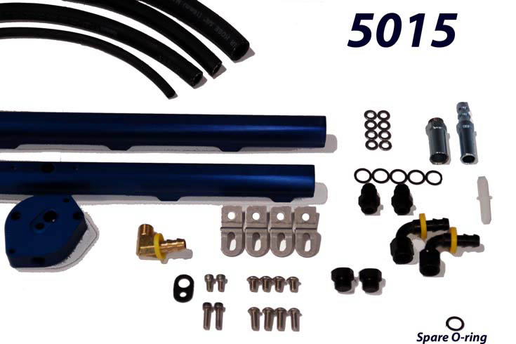
5015 Bill Of Materials
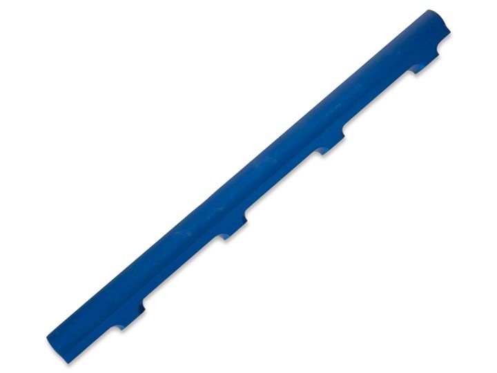
(1) Driver side rail
(1) Passenger Side Rail
(2) 10-32 x 3/4” SHCS
(2) 10-32 x 3/8” SHCS
(4) 1/4”-20 x 3/8” BHCS
(4) M6x1.0x16mm BHCS
(1) Regulator base gasket
(4) Rail mounting brackets
(1) Fuel pressure sensor/regulator adapter
(1) Spring-Lok fitting
(1) Spring Lok-Push Lok fitting
(5) O-Rings (1) Spare
(8) Washers
(1) Plastic vacuum barb
(30”) 5/32 Hose
(30”) 3/8” Hose
(30”) 5/8” Hose
(1) 13” Fuel line hose
(2) 9/16” Rail end plugs
(2) 9/16” Male-Male Rail end adapters
(2) 9/16” 90°Pushlock hose swivel fittings
(1) 1/4” thread to Push Lok 90° fitting
To view a video install of this BBK product visit www.bbkperformance.com and search for part # 5015
