 FREE 1 to 3-Day Delivery on Orders $119+ Details
Best Sellers


How to Install BMR Non Adjustable A-Arms - Polyurethane Bushing - Hammertone (79-93 All) on your Ford Mustang
Installation Time
2 hours
Tools Required
- Jack and jackstands
- Ratchet
- Sockets - 15mm, 18mm, 21mm, 24mm, E8 (external torx)
- Wrenches - 24mm
- Pry-bar or spring compressor
Shop Parts in this Guide
1. Place front of vehicle securely on jackstands, place jack under a-arm that will be removed first.
2. Remove front wheels.
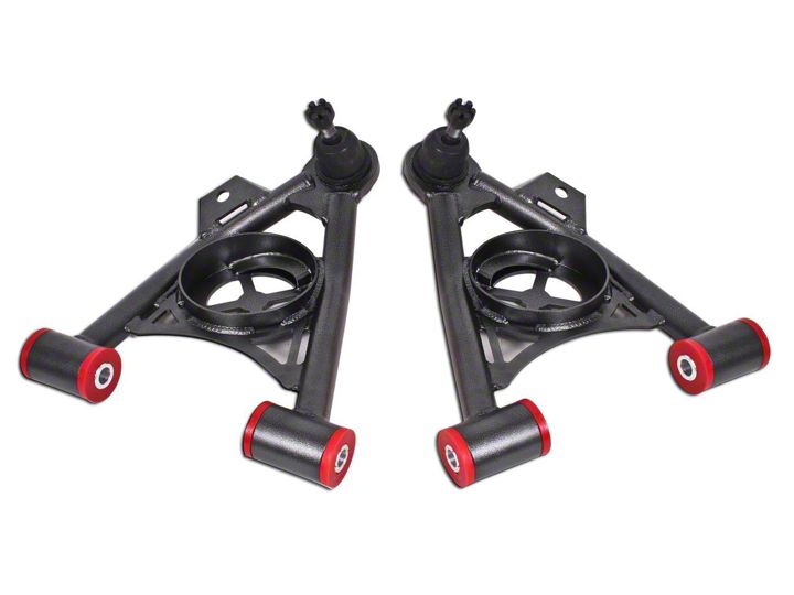
3. Using the 15mm socket, remove sway bar end links as shown in IMAGE 1.
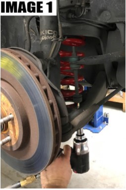
4. Unclip ABS wires as shown in IMAGE 2.
5. Using the E8 socket, remove the ABS sensor.
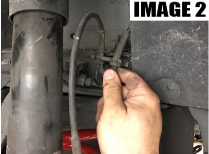
6. Using the 24mm socket, remove the nuts and ABS line bracket from the strut as shown in IMAGE 3.
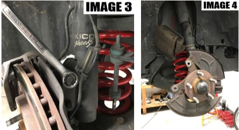
7. Remove 15mm caliper bolts and hang the caliper as shown in IMAGE 4.
8. Using the 21mm socket and 24mm wrench, remove the lower strut bolts. NOTE: Make sure jack is secure and has light pressure on the lower arm before removing strut bolts.
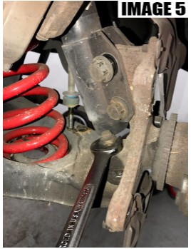
9. Remove 24mm lower ball joint nut as shown in IMAGE 5.
10. Remove spindle, followed by the spring. NOTE: Use caution removing the spring, as it can have a large amount of pressure on it. A spring compressor or an extra person with a pry bar to hold the spring in position is recommended.
11. Using the 21mm socket and 24mm wrench, remove the lower control arm bolts.
NOTE: On some cars the rack may need to be moved to remove the front control arm bolt. Loosen the 15mm and 18mm rack bolts and 13mm steering shaft bolt and slide rack forward to allow removal of control arm bolt.
12. Remove lower control arm.
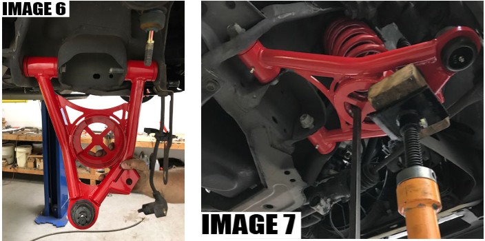
13. Install new lower control arm re-using stock hardware as shown in IMAGE 6.
14. Place jack under new control arm.
15. Install spring, ensuring the spring is clocked correctly and lines up with the spring ramp in the spring cup on the a-arm.
NOTE: If using a spring compressor, compress spring before installing to allow the arm to move upward enough to bolt to the spindle. If you have an extra person, you can use a pry bar to hold the spring in position as you jack up the arm. Use caution as the spring will have a large amount of pressure on it.
16. Using the jack, lift the arm up until the spindle can be reinstalled using the 24mm lower ball joint nut, followed by the 21mm and 24mm strut bolts as shown in IMAGE 7.
17. Tighten 15mm and 18mm steering rack bolts, along with 13mm steering shaft bolt.
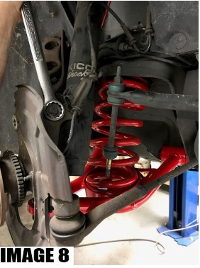
18. Install ABS line bracket and 24mm nuts on strut bolts as shown in IMAGE 8.
19. Using the E8 socket, install ABS sensor and clip ABS wires back in.
20. Install rotor and caliper with 15mm caliper bolts.
21. Reinstall 15mm swaybar endlink bolts
22. Reinstall wheel.
23. Repeat steps for other side.
