 FREE 1 to 3-Day Delivery on Orders $149+ Details
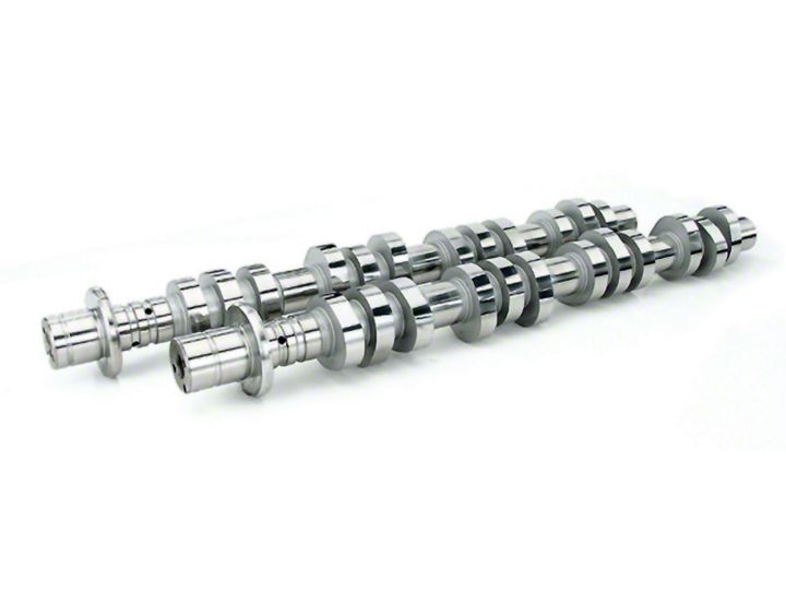
How to Install Comp Cams Camshafts on your 1996-2010 Mustang GT
Shop Parts in this Guide
- Comp Cams Stage 1 XFI NSR 214/227 Hydraulic Roller Camshafts (05-10 Mustang GT)
- Comp Cams Stage 2 XFI NSR 222/235 Hydraulic Roller Camshafts (05-10 Mustang GT)
- Comp Cams Stage 1 XFI VSR 214/227 Hydraulic Roller Camshafts (05-10 Mustang GT)
- Comp Cams Stage 2 XFI VSR 222/235 Hydraulic Roller Camshafts (05-10 Mustang GT)
- Comp Cams Stage 3 Xtreme Energy 234/238 Hydraulic Roller Camshafts (96-04 Mustang GT)
- Comp Cams Stage 1 Xtreme Energy 226/230 Hydraulic Roller Camshafts (96-04 Mustang GT)
Installation
Camshaft Installation
Step 1: Prepare a clean work area and assemble the tools needed for the camshaft installation. The use of an automotive manual is strongly recommended for help in determining which components must be removed from your engine in order to expose the camshafts, camshaft sprockets and timing chain assembly. A good, complete repair manual will save both time and frustration during the installation of your new camshaft set.
Step 2: Remove the intake manifold and valve covers from the motor.
Step 3: Remove the spark plugs, crankshaft pulley, damper and engine front cover.
Step 4: Relieve the tension on the timing chains and remove them.
Step 5: Rotate the crankshaft counterclockwise from the 12 o’clock position, setting the keyway at a 45° angle (about halfway between 10 and 11 o’clock). Note that this step is vital in order to avoid contact between the pistons and valves while rotating the cams for the purpose of rocker arm removal.
Step 6: Rotate the camshaft so that the heel of the cam lobe is positioned over the rocker arm that you wish to remove. Using the appropriate rocker arm service tool, compress the valve spring and remove the rocker arm. Repeat this process until all of the rocker arms have been removed.
Step 7:Once all of the rocker arms have been removed, unbolt and remove the cam towers. Be sure to keep track of the order in which you removed the cam tower caps and cap bolts, as they are not all the same size.
Step 8:Remove the old camshafts. Liberally coat your new COMP Cams® camshafts with the supplied assembly lube. It is a good idea to use an additional bottle of lube, available from COMP Cams® (Part #152) in order to ensure that you have enough lubricant for a proper installation. This is very important as (unlike a conventional small block) pre-lubing the modular motor is difficult without some type of pressurized external oiling system.
Step 9:Install each cam on its proper side of the engine (R=passenger side, L=driver side). Tighten all of the cam tower bolts using factory torque specification and tightening sequence. Verify that each camshaft spins freely without binding (note that slight resistance to turning is normal).
Step 10:Rotate the crankshaft keyway back to the 12 o’clock position, and attach the camshaft gears and timing chains, making sure that the timing marks on the camshaft and crankshaft gears line up with the copper coated links on the timing chains.
Step 11:Use a 1” open end wrench on the hex bolster in the middle of each camshaft to hold it in place, and torque the camshaft bolt to the factory specification. Return tension to the timing chains following the factory recommended procedure.
Step 12:Reinstall the rocker arms using the reverse of the procedure outlined in step 6.
Useful Part Numbers*
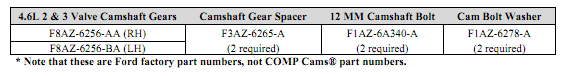
* Note that these are Ford factory part numbers, not COMP Cams® part numbers.
Camshaft Degreeing Procedure
The purpose of degreeing a camshaft is to ensure that it is phased correctly with the crankshaft. Some factors that may cause improper phasing are:
• Camshaft or crankshaft gear marked incorrectly
• Incorrectly machined cam or crank gear keyways
• Misindexed cam keyway or dowel pin
• Improper machining of camshaft or crankshaft
• Accumulation of machine tolerances
The important factor to remember is that correct camshaft phasing is critical for efficient engine operation. COMP Cams® offers all the equipment needed to properly degree in a camshaft, which includes the following:
• Degree wheel (COMP Cams® Part #4790)
• Rigid pointer that can be attached to the engine block (COMP Cams® Part #4794)
• Dial indicator with enough range to measure full cam lift (COMP Cams® Part #4909)
• Magnetic or attachable base to affix the dial indicator (COMP Cams® Part #4907)
• Top dead center stop (COMP Cams® Part #4795)
• A means to attach the degree wheel to the crankshaft. COMP Cams® Pro Crankshaft Socket (Part
#4798) works well for this purpose, as it provides a convenient means of rotating the engine in addition to firmly anchoring the degree wheel in place.
Also required in order to degree your new COMP Cams® 4.6-liter camshafts are a 1” wrench and solid valve adjuster (lifter).
Intake Centerline Method
There are several accepted ways to degree a camshaft. COMP Cams® suggests the intake centerline method as the easiest and most accurate. This method of cam degreeing is very practical and indifferent to engine design characteristics. It simply involves positioning the center, or point of maximum lift, of the #1 intake lobe with Top Dead Center (TDC) of the #1 piston. The intake centerline method still requires accuracy to be correct, but it is somewhat forgiving. Once you have degreed a camshaft using this method, you will be surprised at its ease.
Step 1: The camshafts and timing chains have been installed. Make sure that the timing marks on both the cam gear and crank gear are aligned properly with the copper coated timing chain links as per the camshaft installation instructions.
Step 2: Position the #1 piston at Top Dead Center (TDC). Attach the degree wheel to the balancer or crank socket, and install the assembly on the crankshaft. The crank may be rotated from either the front or from the flywheel end. Obviously, if the engine is in the car, you must rotate from the front. Remember, the greater the leverage, the smoother the crank rotation, and the more accurately you can rotate the crankshaft. Install degree wheel and pointer, and set the pointer to zero on the degree wheel.Note: Never use the starter to turn the engine while degreeing a cam.
Step 3: Rotate the crankshaft opposite the engine rotation direction about 15-20 degrees. This will lower the piston enough to permit the installation of the piston stop in the #1 spark plug hole. Rotate the crankshaft clockwise until the piston hits the stop, and record the number indicated on the degree wheel. Next, rotate the crankshaft counterclockwise until the piston hits the stop from the other direction, and again record the number on the degree wheel.
Step 4:Remove the piston stop after marking the two points on the degree wheel. Rotate the crankshaft to the midpoint of the two marks (this is determined by adding the two points on the degree wheel together, then dividing by 2).This point is TDC for cylinder #1.Without rotating the crankshaft adjust the degree wheel to read
0 degrees at the pointer. You are now ready to locate the intake lobe centerline relative to TDC. If you are not absolutely sure that your zero degree mark is set at TDC, repeat this procedure. This step is critical to proper camshaft alignment.
Step 5:Attach the dial indicator to the dial indicator mount. Position the dial indicator mount so the tip of the dial indicator extension/plunger will contact the retainer of the intake valve. It is important that the indicator plunger be parallel to the valve stem. Any variance in the angle of the indicator will introduce geometric errors into the lift readings.
Step 6:Rotate the crankshaft clockwise until the camshaft reaches maximum intake lift. At this point, the dial indicator will begin to change direction at the point of maximum lift. At this point, set the dial to zero.
Step 7:Rotate the crankshaft counterclockwise until the dial indicator reads.100”. Next, turn the engine forward in the normal direction of rotation until the dial indicator reads.050” before maximum lift. Record the degree wheel reading.
Step 8:Continue to rotate the engine over in its normal direction of rotation until the indicator goes past zero to
.050” on the closing side of maximum lift. Again, record the degree wheel reading.
Step 9:Add the two numbers together and divide by 2. The resulting number will be the location of maximum lift of the intake lobe in relation to the crank and piston. This is the intake centerline. For example: The first degree wheel reading was 100 degrees. The second reading was 120 degrees. These two numbers (100 120) added together will be 220. 220 divided by 2 will equal 110. Your actual intake centerline is 110 degrees.
Verify that your measured intake centerline matches that listed on your camshaft specification card.
Step 10:Repeat the degreeing process on the opposite cylinder bank, this time using the number 6 intake valve to check the intake centerline. Note that it is not necessary to re-establish TDC in order to verify the #6 intake centerline.
In the event that your camshaft did not degree in to the camshaft specification, it will be necessary to either advance (move the cam ahead) or retard (move the cam back) the camshaft to meet the suggested intake centerline. There a couple of degrees of advance/retard available by loosening the timing gears (lock the camshafts again before loosening the bolts!) and rotating the crankshaft until the pointer is positioned at the desired intake centerline reading. Refer back to step 9 if you do not remember how to determine that reading.
Note: When degreeing a cam, remember to look at the degree wheel as two 180 degree sides, no matter how the degree wheel you are using is marked. Many degree wheels are marked in 90 degree increments. On wheels that are marked in 90 degree increments, keep in mind that you must continue to count the number of degrees on past 90 degrees. Be sure all readings are taken from Top Dead Center.
Keep in mind that to advance the cam, you must lower the intake centerline. For example, if your camshaft set has a lobe separation of 114 degrees, moving the intake centerline to 110 degrees advances the cam 4 degrees. Conversely, moving the intakecenterline to 116 degrees retards the camshaft 2 degrees.
Limited Warranty
Competition Cams, Inc. warrants that all of its products are free from defects in material and workmanship, and against excessive wear for a period of (1) one year from the date of purchase. Thislimited warrantyshall cover the original purchaser.
Competition Cams, Inc.’s obligation under this warranty is limited to the repair or replacement of its product.To make a warranty claim, the part must be returned within (1) one year of purchase to the address listed below, freight prepaid. Items covered under warranty will be returned to you freight collect.
It is the responsibility of the installer to ensure that all of the components are correct before installation. We assume no liability for any errors made in tolerances, component selection, or installation.
There is absolutely no warranty on the following: A) Any parts used in racing applications;
B) Any product that has been physically altered, improperly installed or maintained;
C) Any product used in improper applications, abused, or not used in conjunction with the proper parts.
There are no implied warranties of merchantability or fitness for a particular purpose.There are no warranties, which extend beyond the description of the face hereof. Competition Cams, Inc. will not be responsible for incidental and consequential damages, property damage or personal injury damages to the extent permitted by law. Where required by law, implied warranties or merchantability and fitness are limited for a term of (1) one year from the date of original purchase.
This warranty gives you specific legal rights and you may also have other legal rights, which vary from state to state.

