 FREE 1 to 3-Day Delivery on Orders $119+ Details
Best Sellers


How to Install Davies Craig Electric Water Pump - 150 LPH on your Mustang
Shop Parts in this Guide
PLEASE READ THESE INSTRUCTIONS IN THEIR ENTIRETY BEFORE YOU START WORK
THE EWP IS A ‘CIRCULATION’ PUMP IDEAL FOR ‘CLOSED CIRCUIT’ OPERATION SUCH AS AN AUTOMOTIVE COOLING SYSTEM.
DAVIES, CRAIG EWP® (ELECTRIC WATER PUMP) AND OPTIONS FOR PUMP CONTROL
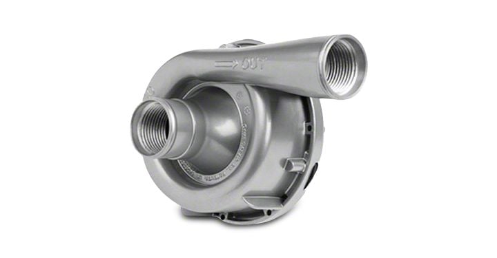
Congratulations on your purchase of the Davies, Craig alloy EWP®150 Electric Water Pump. This high capacity EWP®150 (40 US Gal/Min) is designed to replace and/or complement the existing belt driven mechanical water pump. The major benefits an EWP®150 offers are, removal of the parasitic power losses running a mechanical water pump at high speed when not needed, maximise engine warm-up and removal of the effects of heat soak after hot-engine shut down by operating the EWP®150 with the EWP® & Fan Digital Controller (#8020) or one of the Davies Craig Thermatic Switches. Your new EWP®150 has the advantage of offering more consistent coolant flow independent of the engine speed.
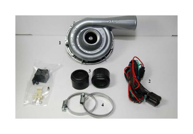
EWP® COMPONENTS:
| No. | Description | Qty. |
|---|---|---|
| 1 | EWP alloy Pump Assy | 1 |
| 2 | Wiring harness with 10Afuse | 1 |
| 3 | Rubber Sleeves | 2 |
| 4 | Hose Clamps | 2 |
HARDWARE COMPONENTS:
| No. | Description | Qty. |
|---|---|---|
| 1 | Hardware bag | 1 |
| 2 | Relay | 1 |
| 3 | Scotch lock | 1 |
| 4 | Ring Terminal | 1 |
| 5 | Self Tapper | 1 |
SECTION ONE: INSTALLING THE EWP® 150
1. Your EWP®150 Electric Water Pump is best fitted in the lower radiator hose which connects the radiator to the existing mechanical water pump housing. In conventional vehicle operating conditions, the hose will carry the weight of your EWP® 150 and insulates the EWP® from engine vibration. Check the area for available space. Further radiator hose or adaptors may be required. Position the EWP® in the lower hose so the inlet, in the centre of the pump is connected to the radiator side and the outlet (marked with an arrow) is connected to the engine’s mechanical water pump housing or EWP Header-Adaptor. The EWP® should be positioned as low as possible to maximise the gravity feed from the radiator and to avoid air entering and remaining in the pump. Alternatively, the EWP® may be fitted in the upper radiator hose. Coolant level is critical and bleeding of all air from the cooling system essential. Follow instructions above for correct EWP® fitment ensuring the pump outlet is connected to the hose going into the top of the radiator. The pump can be installed in any orientation but to assist air bleeding try to mount the outlet pointing upwards.
2. Use Rubber Sleeve Adaptors 2 x 3mm (part #8510) supplied in kit for fitment to the EWP® inlet and outlet, to suit your particular hose diameter. If you require thicker Rubber Sleeve Adaptors to suit 2” (part #8511, 6mm) internal diameter hose contact Davies, Craig Pty Ltd. These can be shipped to you promptly, free of charge.
3. Cut out the not required section of the radiator hose. Connect the pump inlet and outlet to the appropriate hose ensuring hose clamps are very firmly tightened.
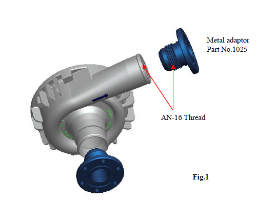
Assembly of flanged adaptors ( Optional )
Your Davies Craig EWP®150 Alloy Electric Water Pump offers you the alternative option to use the AN-16 internal threads in both the inlet and outlet to attach the appropriate adaptors (as shown) or screw-in radiator hoses to suit your individual requirements.
A selection of Davies, Craig adaptors can be ordered separately. Please consult our website www.daviescraig.com.au or your authorised Davies Craig stockist.
SECTION TWO: OPTIONS FOR PUMP CONTROL
1. With EWP® Fan Digital Controller, P/No - 8020:
We highly recommend the use of the EWP/Fan Digital Controller for maximum cooling efficiency. The EWP/Fan Controller will vary the EWP speed in response to the coolant temperature. You set the temperature desired for maximum power or fuel efficiency. The Digital Controller has an in built function that allows the EWP to run on after hot engine shutdown to eliminate heat soak. We further recommend the removal of the engine’s thermostat and disabling of mechanical water pump. The pump belt can either be removed or left as an idler pulley. The vehicles heater may take a little longer to warm up and to improve the heating; we recommend the fitment of an Electric Booster Pump (EBP) Part No.9002 to the heater line
2. With Davies, Craig Thermatic Switches, Part #0401 or Part #0402
Combine the EWP® with either of the approved Davies, Craig thermal switches listed here when the EWP is used as a booster pump to assist the existing mechanical water pump cool an overheating engine. Connect the thermal switch directly to the battery and your EWP will run on to eliminate heat soak. You may leave the thermostat in place , but ensure the EWP operates only when the thermostat is open.
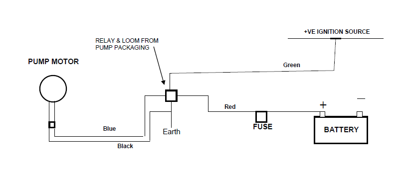
3. Continuous running:
Wire the EWP® direct to the ignition for maximum cooling (race vehicles, very hot climates). This option requires the removal of the Engine thermostat and the mechanical pump impeller or pump belt. This option may also be used for road cars with the thermostat in place with a small hole (suggest 5mm), allowing a small amount of flow to circulate even when the thermostat is closed.
WARNING: When using the Electric Water Pump (EWP) on vehicles using LPG, it is recommended that an Electric Booster Pump (EBP - Davies, Craig part no 9001)) be fitted to the heater circuit to increase the flow through the heater line and therefore eliminate the risk of freezing LPG in the converter.
MODIFYING EXISTING MECHANICAL WATER PUMP
Either:
1. Remove the existing belt-driven water pump housing.
2. Remove the water pump impeller from the pump shaft. (NOTE: You may need to drill holes through the impeller close to the drive shaft to make it easier to eliminate same). Alternatively, remove vanes from impeller. Mechanical water pumps differ from engine to engine and you need to take appropriate action that suits the specific water pump to eliminate the impellor.
3. Re-fit the water pump housing without the impeller ensuring that there is no damage to the water pump gasket and the pump seal is still retained. Re-fit the water pump belt and tighten to manufacturer’s specifications.
Or:
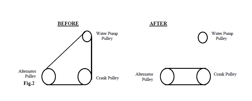
1. You may choose to by-pass the belt-driven water pump pulley by installing a shorter belt. This option may not be possible if the crank pulley drives a belt-driven power steering and fan or unless you replace the mechanical fan with a Davies, Craig Thermatic Fan®. For example see Fig 2 below:
2. Remove the thermostat from the thermostat housing.
3. Re-fit the thermostat housing ensuring that there is no damage to the thermostat-housing gasket.
OPTION 1: INSTALLING EWP® & FAN DIGITAL CONTROLLER - Part # 8020
NOTE: Wiring from EWP kit will not be required however retain for hard wiring the EWP during bleeding.
1. The Digital Controller must be fitted inside the passenger compartment.
2. Connect the wiring harness to the Digital Controller and mount the Controller (using 2 of the screws provided) in an appropriate position --- avoid mounting the controller where it may be exposed to direct sunlight.
3. An additional screw is provided for mounting Digital Controller fuse holder where necessary.
4. Mount ‘Remote Test Light’ in a location, which will be visible. The ‘Test Light’ may be fitted by inserting it through a 4.6mm drilled hole in a plastic area of the interior/dashboard or simply with adhesive tape.
5. For installation of the sensor in the position of the thermostat refer to the Digital Controller instruction booklet.
6. Bleed the EWP®. Refer to “BLEEDING THE EWP®” on page 7. After bleeding the EWP® continue with the installation process.
OPTION 2: USING THE EWP®150 AS A BOOSTER PUMP
This option when combined with a Davies, Craig Thermatic Switch, Part #0401 or Part #0402 will turn the EWP® on at the temperature you set, to give an added boost to an overheating cooling system.
INSTALLING THERMAL SWITCH ( Part No. 0401 OR 0402)
Refer wiring diagram 2a & 2b below.
For detailed instructions on installing switches, please refer to 0401 & 0402 instruction sheets.
Bleed the EWP®. Refer to “BLEEDING THE EWP®” on page 7. After bleeding the EWP® continue on with the next stage.
WIRING DIAGRAM 2a: EWP®WITH THERMAL SWITCH - PART # 0401:
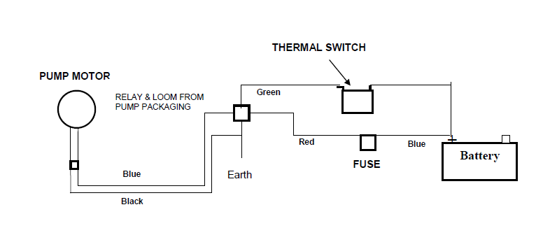
WIRING DIAGRAM 2b: EWP®WITH THERMAL SWITCH - PART # 0402

OPTION 3: CONTINUOUS RUNNING (Recommended for race vehicles, very hot climate and cars running on LPG.)
Continuous EWP®150 Alloy Electric Water Pump operation may be required for some road or race engine applications, in some very hot climatic conditions and engines fitted with liquid petroleum/butane gas (LPG) conversion.
This option will provide maximum flow from your EWP®150 under all operating conditions without a Digital Controller or a Thermatic Switch fitted. Should you choose this method you should retain the engine thermostat and drill one or two holes (suggest 5mm) in the plate to ensure a small volume of coolant flows through the cooling system during operation. Depending on the operating temperature required in some engines, the centre of the thermostat plate may need to be removed.
WIRING DIAGRAM 3: EWP® CONTINUOUS RUNNING:
BLEEDING THE EWP®
1. Fill the entire engine cooling system with appropriate coolant.
2. Do not start the engine
3. Hardwire the EWP® directly to the vehicle’s battery or a 12v power source.
4. With the radiator cap off, run the EWP® for short periods to ensure no air is trapped in the cooling system. Top up the radiator with coolant ensuring all air is totally eliminated from the entire cooling system. Re-run the EWP®150 for a short period.
5. Replace the radiator cap and reconnect the EWP®150 to the wiring system supplied.
RUNNING THE EWP®
Start engine to confirm no leakage at radiator hose and re-torque radiator hose clamps. Monitor the engine temperature, which should take longer than usual to reach steady state. If the ignition is left on (or if a turbo timer is connected) after a hot shut down, the pump will continue to run and stop engine heat soak. Re-tighten the hose clamps after a few hours running at temperature and again after 20 hours running. Check for leaks. NB: The heater circuit may take longer than normal to warm up.
EWP®150 INSTALLATION RECOMMENDATIONS
To ensure maximum life and optimum performance from your new EWP Davies, Craig recommends:
• Storage - If a EWP® is installed in your vehicle’s engine cooling system, stored and/or not started or driven for more than 3 months, e.g. a show/static display or race car, it’s strongly recommended the EWP® is operated for approximately 5 mins constant running every month. This will minimise the build-up of any sediment in the EWP and also lubricate all parts within the pump.
• Heater - For improved heater performance on vehicles which have the heater inlet (return) and outlet ports in the mechanical pump housing (referred to in “Warnings”), Davies, Craig suggest the fitment of the Electric Booster Pump, EBP, part # 9001. This unit fits into the heater hose and boosts coolant flow through the heater circuit and/or cylinder heads. Check out website www.daviescraig.com.au
• LPG (Liquid Petroleum Gas or Butane) vehicles require constant flow through the LPG converter and if the EWP is used in conjunction with the EWP® & Fan Digital Controller, we recommend the installation of an Electric Booster Pump EBP® to overcome the converter body freezing at start up.
• As a preventative measure, we strongly recommended you flush out your engine’s cooling system every 6 months or 10,000kms to help remove any built up of sediment.
WARNINGS
• Do not operate your EWP® dry as seal damage may occur and your warranty may be jeopardised.
• Use of the EWP® after removing the pump impeller or deleting the mechanical pump pulley from the belt system may increase maximum engine speed. Running an engine at higher than normal speeds may affect other engine components.
• Engine temperature must be monitored closely at all times more especially after installation and until your EWP® operational procedures have reached your expectations.
• The EWP® can handle most rust particles, shale and sludge found in cooling systems but large rust particles should be flushed from the radiator before the EWP® is installed.
• Some engines may require special bleeding procedures to remove all air from their cooling system. The EWP® must be completely full of coolant at all times to achieve the life expectations of your EWP® and to ensure your warranty is not jeopardised.
• Do not use the vehicle’s engine management system or wiring connected to the vehicle’s engine management system (ECU) as an ignition source as it may cause failure of the management system and/or the electrical system. The ignition source for your EWP®150 Electric Water Pump and EWP® & Fan Digital Controller Combo Kit must be a steady positive supply of 12-14V DC.
• Vehicles with both heater circuit inlet (return) and outlet ports in the mechanical pump housing will suffer reduced heater performance unless the heater returns position is relocated.
• The engine cooling system must use coolant as specified by the vehicle’s manufacturer.
• The EWP® is a ‘circulation’ pump ideal for most ‘closed circuit’ pressurised automotive cooling systems.
• The EWP® is not a ‘self-priming’ water pump and therefore will not produce its full flow without a positive ‘head’ in an ‘open’ system.
• The EWP® impeller tip clearance has been designed to achieve maximum efficiency and is therefore very close to the housing. When new and bedding in, the impellor may touch the internal wall of the EWP® housing causing a slight noise. This sound will cease within a very short time.
FITTING OPTION:
EWP® HEADER-ADAPTOR KITS ~ Suit Chevrolet Small & Big Block engines
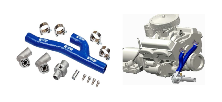
To complement the fitment of your EWP®150 Electric Water Pump and EWP® & Fan Digital Controller Combo Kit to your Chev BB or SB engine, a EWP® Header-Adaptor Kit is available to replace the existing mechanical water pump. These simple do-it-yourself kits are supplied with fitting instructions and a 3D video is available for viewing on our website www.daviescraig.com.au
WARRANTY
We warrant that for a period of two years or 2000 hours continuous running (whichever is the lesser) from the date of purchase, we shall carry out, free of cost, any repairs that are reasonably necessary to correct any fault in the operation of your Electric Water Pump provided that such a fault is directly attributable to a defect in the workmanship or materials used in the manufacture of the part(s) and is not due to installation other than described in these instructions. Labour and consequential costs are excluded. DAVIES, CRAIG PTY. LTD.
