FREE 1 to 3-Day Delivery on Orders $149+ Details
How to Install a Scott Drake Fuel Rails on your 2007-2012 Mustang GT500
Installation Time
3 hours
Tools Required
- 3, 5, & 6mm allen wrenches
- 8 AN (or 7/8") open end wrench
- 10 AN (or 1 ") open end wrench
- 1 1 /8" open end wrench
- Light machine oil
- Spring lock coupling tool (Ford 31 0-S039 or equivallent)
- Ratchet with 6" extension & assortment of metric regular & deep sockets~
- Note: Installation requires a new vacuum hose, Ford part # BR3Z-9F72-HS or equivallent fabricated hose
Installation
WARNING!
Do not smoke, carry lighted tobacco or have an open flame of any type in the area where installation is taking place. Highly flammable mixtures are always present and may be ignited. Do not carry personal electronic devices such as cell phones or audio equipment when performing installation. Failure to follow this warning may result in serious personal injury.
WARNING!
Do not attempt installation before relieving fuel pressure as outlined in step 1 below.
WARNING!
Please review these instructions carefully. If any part of this procedure seems out of your scope of capabilities, please seek a certified mechanic to perform this installation.
INSTALLATION
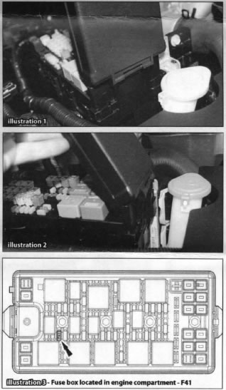
Step 1. Relieve fuel pressure by opening the fuse box cover (Illustration 1 & 2) and removing the fuel pump module fuse as shown (Illustration 3). Start the engine and allow it to run until it stalls. After engine stalls, crank engine for approximately 10 seconds to ensure fuel injection pressure has been relieved. If engine fires, repeat cranking until engine does not attempt to start. Turn ignition switch to off position.
Step 2. Disconnect negative battery cable from battery.
Step 3. Unbolt and remove strut tower brace (Illustration 4).
Step 4. Disconnect Crankcase Vent Outlet pipe and Vacuum Tube Outlet pipe from air intake assembly. Remove clamps holding Inlet tube to Throttle Body and remove Inlet Tube as shown (Illustration 5).
Note: This step will vary if an aftermarket induction package is installed. Removing the inlet tube assembly from the throttle body is the requirement for this step, however it is accomplished.
Step 5. Disconnect IAT2 connector, Fuel Rail PressurelTemperature Sensor connector, and Throttle Position Sensor connector as shown. Disconnect Fuel Rail/Temperature Sensor vacuum hose at both ends as this will need to be replaced with Ford Part Number 7R3V-9E498-BA or suitable fabricated hose (Illustrations 6 & 7).
Step 6. Remove fuel supply spring lock coupling as shown (Illustration 8 & 9), using the appropriate fuel line disconnect tool (Ford Tool number 310- S039 or equivalent).
Step 7. Disconnect the electrical connectors to the 8 injectors.