 FREE 1 to 3-Day Delivery on Orders $119+ Details
Best Sellers


How to Install Auto Meter Hoonigan Boost/Vacuum Gauge - 30 psi Mechanical on your Mustang
Shop Parts in this Guide
ON MECHANICAL VAC/BOOST GAUGES
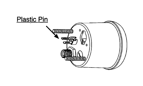
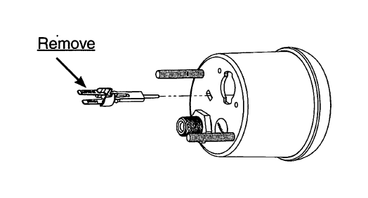
To maintain proper calibration during shipping, the pointer of this gauge is held off zero by a plastic "pin" inserted into the gauge case and movement. This pin MUST BE REMOVED and discarded prior to installation and operation
VENTING FOR LIQUID FILLED GAUGES ONLY
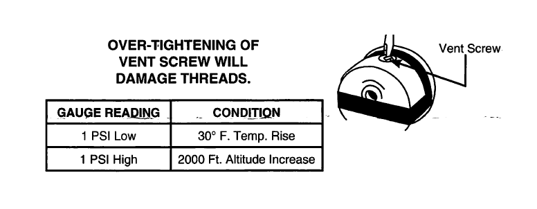
Auto Meter's Pro Comp Liquid Filled Gauges are equipped with a vent screw on the top of the case. Internal case pressure can change due to altitude, barometric pressure, and temperature, causing an inaccurate or "off zero" reading on more sensitive low pressure gauges such as 0-15 psi fuel pressure, vacuum, boost, and vacuum/boost gauges. To prevent this it is recommended that the gauge be vented.
With the vent screw in the upright position, turn the screw two turns counterclockwise to equalize the gauge case pressure. This allows the gauge to breathe and self adjust.
Note on Ultra-Nite (Glow In The Dark)
The glow in the dark coating on the dial of the Ultra-nite gauge may turn gray if exposed to direct sunlight for extended periods of time. When the car is not being used and will be in direct sunlight for long periods of time, place the provided red plastic cover on the gauge.
LED REPLACEMENT KITS ARE SOLD ONE PER PACKAGE
3284-Red LED Replacement Kit, 3285-Green LED Replacement Kit, 3286-Blue LED Replacement Kit, 3287-Amber LED Replacement Kit, 3288-White LED Replacement Kit
Metric Adapters
If this product is to be installed on a vehicle requiring metric fittings, please contact your local Auto Meter dealer to purchase metric adapters. A complete listing of the fittings available can be found in our catalog or online at http://www.autometer.com
PRESSURE, VACUUM & BOOST GAUGES
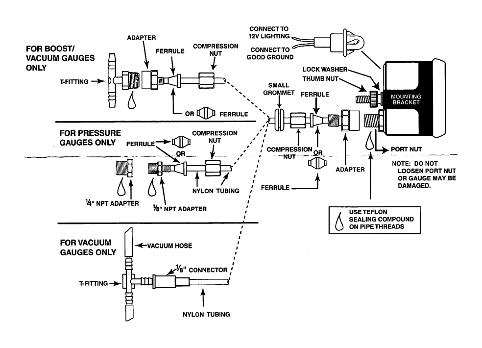
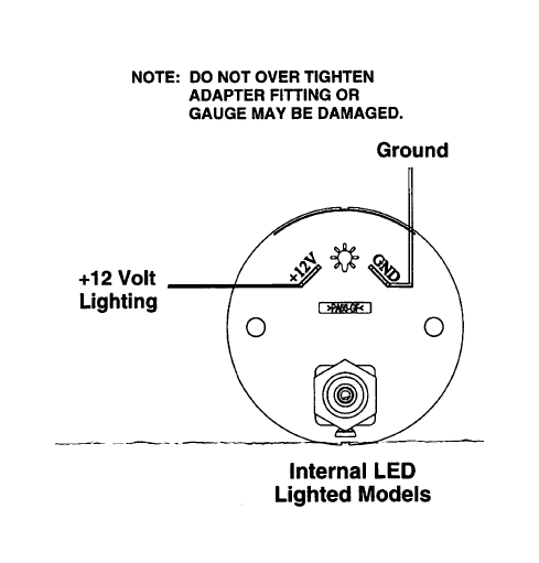
NOTE : DO NOT OVER TIGHTEN ADAPTER FITTING OR GAUGE MAY BE DAMAGED.
NOTE: Some late model vehicles use electronic sensors in their pressure and temperature senders for engine control functions. Before removing the original sender, we recommend that you contact your automotive dealer to be sure no critical functions will be disrupted. With pressure gauges, it is beneficial to add a T-fitting to install your new gauge and to keep the warning light operational. This allows you to monitor the pressure and still have a warning light to indicate emergency conditions.
1. Gauges may be mounted in In-dash holes, or in Auto Meter custom mounting Solutions. Secure gauge with mounting clamps supplied. 2-1/16"gauges mount in 2-1/16" diameter hole, 2-&13" gauges mount in 2-SB" diameter hole.
2. Drill 3^" dia. holes and install rubber grommet where pressure or vacuum line passes through sheet metal, such as firewall.
3. Attach nylon pressure line to fitting on back of gauge using adapter, ferrule, and compression nut as shown in diagram above. Route line through grommet to engine compartment. Connect line to pressure port on engine by using 1/B" adapter (1/4" if needed), ferrule and compression nut for pressure gauges or 1/8" connector and T-fitting for vacuum gauges.
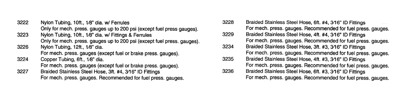
4. Make sure line is free from hazard of moving parts or hot engine components. It is recommended that Auto Meter 3224 copper tubing kit be used where a potential hazard e x i t s .
5. Start engine and thoroughly check installation for leaks.
6. Twist in light socket assembly and connect one wire to dash lighting circuit or other 12V power source and the other wire to a good ground.
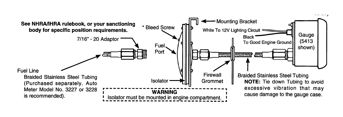
FUEL PRESSURE GAUGES (W/ ISOLATOR)
1. Install gauge and tubing assembly in an in-dash hole that is 2-VI6" in diameter for 2-VI6" models and 2-56" diameter for 2-58" models. Gauge may also be mounted in Auto Meter Accessory underdash panels. Securely mount gauge using mounting bracket provided. If mounting gauge is somewhere other than in-dash or underdash, you may be required to fabricate necessary provision.
2. Isolator must be mounted in engine compartment. (DO NOT mount on firewall per NHRA/1HRA rules.) Drill two 1764" dia. holes in desired location. Mount isolator mounting bracket using the bolts, lockwashers, and nuts provided. Gauge and isolator should be mounted at the same height to insure accurate readings. If not mounted level with each other, the fluid weight will cause a slight accuracy error.
3. Drill a 7/Q" dia. hole in firewall in line with center of mounting bracket. Route the braided tubing through hole into engine compartment.
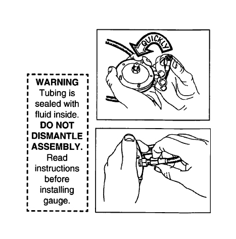
4. With filled portion of isolator in upright position, remove dust plug. Pull braided tubing through center of isolator bracket and hold end in upright position. Remove dust plug and quickly thread braided tubing into isolator port (be careful not to spill any fluid).
NOTE: Fluid leaking from system will cause gauge to read incorrectly. If leakage occurs, fill isolator with solution of half water, half propylene glycol (antifreeze). Repeat Step 4.
5. Secure fuel pressure isolator to mounting bracket using the lockwashers and nuts provided.
6. Slit rubber grommet provided and position in firewall hole so braided tubing holds firmly in place.
7. Determine most desirable location (in line between fuel pump and carburetor) to plumb into fuel system. Thread necessary adaptor fittings into fuel side of isolator.
NOTE: Use thread sealant on all pipe threads to insure a leak free seal.
8. Tee isolator into vehicle's fuel system. We highly recommend that Auto Meter braided stainless steel tubing (Models 3227, 3228, or 3229) be used for this application.
9. With engine running, check to make sure gauge pointer moves in a smooth manner and reads the correct idling pressure.
10. Connect white light wire to dash lighting circuit or other 12V source. Connect black wire to good engine ground.
Bleed Screw
Should excess air in the fuel side of the isolator cause erratic gauge action, bleed excess air out by just loosening the bleed screw enough to allow air passage. Do not remove the bleed screw.Tighten screw when fuel trickles out.
SERVICE
For service send your product to Auto Meter in a well packed shipping carton. Please include a note explaining what the problem is along with your phone number. If you are sending product back for Warranty adjustment, you must include a copy (or original) of your sales receipt from the place of purchase.
