 FREE 1 to 3-Day Delivery on Orders $119+ Details
Best Sellers


How to Install JMS LaunchMAX Digital TransBrake Kit for 6R80 Transmission - Splice In on your Mustan
Shop Parts in this Guide
Step 1 - Locate vehicle EC U, Disconnect Battery
• Ignition key off, remove key from ignition.
• Open the vehicle’s hood. Disconnect the Battery.
• Locate the vehicle ECU (under the hood, near the front passenger side of the vehicle).
• Disconnect the TOP ECU Connector.
Note: Move the grey lever to release the connector from the ECU.
2015 Mustang connector has 95 pins
2011-2014 Mustang connector has 50 pins
• Unwrap six inches of black tape that protects the
wires entering the TOP ECU Connector.
Step 2 - Locate and Cut two EC U wires
• Locate the two Transmission Wires to CUT.
Unwrap the tape 6 inches back from the connector.
Verify and Cut each wire 3 inches from connector.
• 2015 Mustang 6R80 Auto 5.0L & 3.7L
(95 Pin Top Connector) *2.3L is different see step 3
Locate and cut two wires 3” from the top connector
Wire 1 PC3 - Grey with Orange Tracer -> Pin 73
Wire 2 PC2 - Green with Brown Tracer -> Pin 74
• 2011 - 2014 Mustang 6R80 (50 Pin Top Connector)
Locate and cut two wires 3” from the top connector
Wire 1 PC3 - Grey with Orange Tracer -> Pin 45
Wire 2 PC2 - Green with Brown Tracer -> Pin 44
Step 3 - Sold er EC U wires to LaunchMAX harness
2015 - 2016 Mustang - 5.0L and 3.7L • 2015 - 2016 F150 - 5.0L
White Wire (grey cable) -> solder to the wire from ECU Connector: Pin 73 PC3 Grey with Orange Tracer
Brown Wire (grey cable) -> solder to the wire from ECU Connector: Pin 74 PC2 Green with Brown Tracer
Green Wire (grey cable) -> solder to the wire harness: Green with Brown Tracer
Yellow Wire (grey cable) -> solder to the wire harness: Grey with Orange Tracer
2015-2016 Mustang - 2.3L EcoBoost Engine
White Wire (grey cable) -> solder to the wire from ECU Connector: Pin 73 PC3 Grey with Orange Tracer
Brown Wire (grey cable) -> solder to the wire from ECU Connector: Pin 45 PC2 Green
Green Wire (grey cable) -> solder to the wire harness: Green
Yellow Wire (grey cable) -> solder to the wire harness: Grey with Orange Tracer
2011 - 2014 Mustang - 5.0L and 3.7L • 2011 - 2014 F150 - 5.0L
White Wire (grey cable) -> solder to the wire from ECU Connector: Pin 45 PC3 Grey with Orange Tracer
Brown Wire (grey cable) -> solder to the wire from ECU Connector: Pin 44 PC2 Green with Brown Tracer
Green Wire (grey cable) -> solder to the wire harness: Green with Brown Tracer
Yellow Wire (grey cable) -> solder to the wire harness: Grey with Orange Tracer
2011 - 2016 F150 - 3.5L EcoBoost Engine
White Wire (grey cable) -> solder to the wire from ECU Connector: Pin 75 PC3 Grey with Orange Tracer
Brown Wire (grey cable) -> solder to the wire from ECU Connector: Pin 45 PC2 Green with Brown Tracer
Green Wire (grey cable) -> solder to the wire harness: Green with Brown Tracer
Yellow Wire (grey cable) -> solder to the wire harness: Grey with Orange Tracer
Step 4 - Connect LaunchMAX to 12v Key-ON Power and to Ground
• Connect Grey and Red Wires (grey cable) to 12v Key-ON Power.
Both of these wires must be connected to 12V when the key is ON and in the Start position. Solder connections if possible.
• Connect the Pink Wire (grey cable) to Vehicle Ground.
Choose a good ground and bond to gound with a solid connection (screw or bolt).
Solder connections if possible.
Step 5 - Connect LaunchMAX to One Side of a Momentary Switch and the other side to Ground
• Connect the Blue Wire (grey cable) to one side of a momentary switch.
Solder connections if possible.
• Connect the other side of a momentary switch to GROUND.
Choose a good ground and bond to gound with a solid connection (screw or bolt).
Solder connections if possible.
• The momentary switch should be Normally Open.
When the switch is pressed the two connections should make contact and activate LaunchMAX.
Step 6 - (Optional) Connect LaunchMAX to Momentary Switch & MSD 2-Step Activation
• Connect the Blue Wire (grey cable LaunchMAX) to the 3 wire connector on the MSD (Blue Wire)
• When the momentary switch is pressed (closed) ground will be applied to LaunchMAX and the MSD.
Step 7 - Use electrical tape to insul ate all connections, Reconnect EC U Plug , Reconnect Battery
• Insulate all connections using electrical tape.
• Reconnect the WireHarness plug to the ECU. Be sure to replace the tape that was removed in step 1.
• Reconnect the Battery
Step 8 - Test LaunchMAX
• Do NOT ENABLE LaunchMAX when the vehicle is moving. Catastrophic Transmission Damage may occur if the LaunchMAX is enabled when the vehicle is moving.
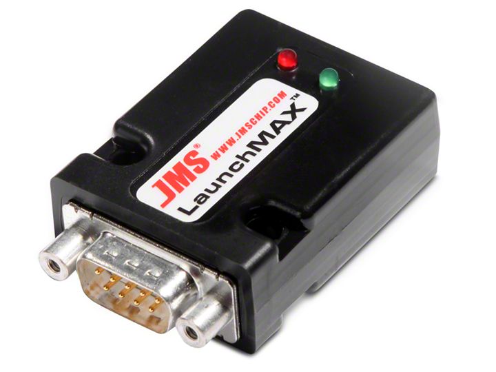
• Turn the KEY-ON and verify that the GREEN LED is ON.
• When the momentary switch is pressed (closed) the RED LED on LaunchMAX will turn ON. If the RED LED is on the TRANS-BRAKE is enabled.
LaunchMAX Install ation is complete.
LaunchMAX - Optional 12v Activate Wiring (three steps)
How to Wire LaunchMAX so it can be enabl ed via a momentary switch and 12V
You Must Use The Optional Steps for 4, 5 and 6 to enable LaunchMAX with 12v.
Optional LaunchMAX Activate 12v DC (step 1)
Step 4 - Connect LaunchMAX to 12v Key-ON Power and to Ground
• Connect Grey Wire (grey cable) to 12v Key-ON Power.
This wire must be connected to 12V when the key is ON and in the Start position.
Solder the connection if possible.
• Connect the Pink Wire and Blue Wire (grey cable) to Vehicle Ground.
Choose a good ground and bond to gound with a solid connection (screw or bolt).
Solder the connections if possible.
Optional LaunchMAX Activate 12v DC (step 2)
Step 5 - Connect LaunchMAX to One Side of a Momentary Switch and the other side to 12V DC
• Connect the Red Wire (grey cable) to one side of a momentary switch.
Solder connections if possible.
• Connect the other side of a momentary switch to 12v Key-On Power.
Solder connections if possible.
• The momentary switch should be Normally Open.
When the switch is pressed the two connections should make contact and activate LaunchMAX.
Optional LaunchMAX Activate 12v DC (step 3)
Step 6 - (Optional) Connect LaunchMAX to Momentary Switch & MSD 2-Step Activation / NO S
• Connect the Red Wire (grey cable LaunchMAX) to the 3 wire connector on the MSD (White/Blue Wire).
• Connect the Red Wire (grey cable LaunchMAX) to the 12v Activate wire on your NOS Controller.
• When the momentary switch is pressed (closed) 12v will be applied to LaunchMAX,MSD & NOS.
• Note: You will typically only use the optional 12v wiring in the event of a NOS controller that requires a 12v signal to Activate.
DB9 Wiring Reference - LaunchMAX (Ground Activation Wiring)
DB9 Pin 1 -> white wire -> input 1 -> ECU Connector: PC3 Grey with Orange Tracer (73 - 2015) (45 - 2011-2014)
DB9 Pin 2 -> brown wire -> input 2 -> ECU Connector: PC2 Green with Brown Tracer (74 - 2015) (44 - 2011-2014)
DB9 Pin 3 -> green wire -> output 2 -> Connect to OE Wire Harness Green with Brown Tracer
DB9 Pin 4 -> yellow wire -> output 1 -> Connect to OE Wire Harness Grey with Orange Tracer
DB9 Pin 5 -> grey wire -> connect to Pin 8 Red -> connect Grey and Red wires to 12v Key ON Power
DB9 Pin 6 -> pink wire -> connect to GROUND
DB9 Pin 7 -> blue wire -> connect to ONE side of a momentary switch, connect the other side to GROUND
Optional - MSD 2-step connect 3 pin msd blue wire to the LaunchMAX DB9 pin 7 blue wire.
DB9 Pin 8 -> red wire -> connect to Pin 5 Grey -> connect Grey and Red wires to 12v Key ON Power
DB9 Wiring Reference - LaunchMAX ( 12 Activation Wiring)
DB9 Pin 1 -> white wire -> input 1 -> ECU Connector: PC3 Grey with Orange Tracer (73 - 2015) (45 - 2011-2014)
DB9 Pin 2 -> brown wire -> input 2 -> ECU Connector: PC2 Green with Brown Tracer (74 - 2015) (44 - 2011-2014)
DB9 Pin 3 -> green wire -> output 2 -> Connect to OE Wire Harness Green with Brown Tracer
DB9 Pin 4 -> yellow wire -> output 1 -> Connect to OE Wire Harness Grey with Orange Tracer
DB9 Pin 5 -> grey wire -> connect Grey wire to 12v Key ON Power
DB9 Pin 6 -> pink wire -> connect to Blue Wire Pin 7 -> connect Pink and Blue wires to GROUND
DB9 Pin 7 -> blue wire -> connect to Pink Wire Pin 6 -> connect Blue and Pink wires to Ground
DB9 Pin 8 -> red wire -> connect to ONE side of a momentary switch, connect the other side to 12v Key on Power
Optional - MSD 2-step connect 3 pin msd white/blue wire to the LaunchMAX DB9 pin 8 red wire.
Optional - Connect NOS or Turbo Controller to the LaunchMAX DB9 pin 8 red wire.
