FREE 1 to 3-Day Delivery on Orders $119+ Details
Best Sellers


How to Install Maximum Motorsports Drag Race Front Control Arms w/ Delrin Bushings (79-93 All) on your Ford Mustang

Shop Parts in this Guide
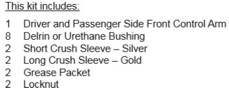
- Maximum Motorsports Drag Race Front Control Arms with Delrin Bushings (79-93 Mustang)
- Maximum Motorsports Drag Race Front Control Arms with Delrin Bushings (94-04 Mustang)
- Maximum Motorsports Drag Race Front Control Arms with Urethane Bushings (79-93 Mustang)
- Maximum Motorsports Drag Race Front Control Arms with Urethane Bushings (94-04 Mustang)
- Maximum Motorsports Non-Offset Front Control Arms with Delrin Bushings (79-93 Mustang)
- Maximum Motorsports Non-Offset Front Control Arms with Urethane Bushings (79-93 Mustang)
Read all instructions before beginning work. Following instructions in the proper sequence will ensure the best and easiest installation.
NOTE: The MM Front Control Arms require the use of a front coil-over conversion kit.
NOTE: The MM Front Control Arms can be installed on most aftermarket K-members which have the same control arm mounting point dimensions as the stock K-member.
Pre-installation Preparation
1. Grease all exposed metal surfaces of the control arm pivot tubes. Grease the outside diameter of the bushings with the supplied grease.
2. Insert the bushings into the control arm pivot tubes.
3. Grease the inside diameter of the bushings.
4. Insert the steel crush sleeves into the bushings.
NOTE: There are two lengths of crush sleeves. The shorter sleeve is silver and belongs towards the front end of the car. The longer sleeve is gold and belongs towards the rear end of the car.
MM K-member Installation
All MM K-members built after 3/11/2008 include a set of our MMF-2 Low Profile Front Control Arm Bolts that are intended to be used on the forward pivots of the front control arms. Please follow the directions carefully to ensure proper installation.
1. Grease all exposed faces of the front control arm bushings using the supplied grease.
2. Slide the control arm into place on the K-member with the sway bar mount facing toward the front of the car.
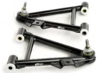
3. Install one of the provided MM Low Profile Front Control Arm Bolts into the forward pivot of each control arm. Install the stock pivot bolts into the rearward pivots using a 5/8” washer under the head (supplied with the K-member). The washer prevents the rearward bolts from bottoming out before the nut is fully tightened.
NOTE: The MM K-member requires all pivot bolts to be installed with the bolt heads toward the front of the car.
4. Thread a factory nut onto each pivot bolt.
5. Hold the head of the MM Low Profile Front Control Arm Bolt stationary using a T-55 Torx socket and tighten the nut. Torque the nut to 148 ft-lbs.
NOTE: The MM Low Profile Front Control Arm Bolts require holding the head of the bolt in place with a T-55 Torx socket while tightening the nut. Do NOT turn the Torx head to tighten. Instead, hold the bolt still with the T-55 socket and turn the nut to tighten.
6. Torque the remaining MM Low Profile Front Control Arm Bolt using the same procedure described above.
7. Torque the rearward, stock control arm pivot bolts to 148 ft-lbs.
NOTE: Return to the MM K-member instructions now if you are installing one.
8. Insert the ball joint stud up through the spindle.
9. MM Front Control Arms are supplied with a locknut for the ball joint. Install the nut and torque it to 129 ft-lbs.
10. Re-attach the swaybar end links. 11. Have the front end professionally aligned.
Stock K-member Installation
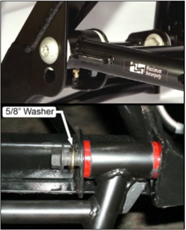
NOTE: The stock K-member must be modified to accept the MM Front Control Arms.
1. The inner mounting flanges of the stock K-member must be shortened so they protrude only 1-1/4” from the center of the control arm mounting holes. This can be done with a reciprocating saw (jig saw or sawsall), cut-off wheel in a die grinder, a hand-held grinder, oxy-acetylene torch, or a combination of these tools.
2. Paint the exposed metal edges to prevent rust.
3. Grease the exposed faces of the bushings.
4. Slide the control arm into place on the K-member with the swaybar mounts facing toward the front of the car.
5. Reinstall the original factory control arm pivot bolts and nuts.
6. Torque the control arm pivot bolts to 148 ft-lbs.
7. Check that the control arm pivots freely. If it does not pivot freely, there are three likely causes:
• Misalignment of the four pivot holes in the stock K-member. Those four holes must be in perfect alignment. Use a 5/8” rod that is long enough to pass through all four pivot holes to check the alignment. If they are not in alignment, you will have to align the hole(s) by using a file or Dremel tool to move each hole so they are all in a straight line.
• Delrin Bushings Only: The face of each control arm tab, where the bushings make contact, may contain weld spatter. This spatter must be removed so the bushing has a smooth surface to rotate against.
• Delrin Bushings Only: The curved stamping of the stock K-member may be touching the outer diameter of the Delrin bushings. You will have to carefully note where the bushing may be touching and sand the Delrin away so that it clears the stamping of the stock K-member.
8. Insert the ball joint stud up through the spindle.
9. MM Front Control Arms are supplied with a locknut for the ball joint. Install the nut and torque it to 129 ft-lbs.
10. Re-attach the swaybar end links.
11. Have the front end professionally aligned.
We recommend greasing the control arm pivots every 10,000 miles. The best grease is a Teflon based grease (available in two different size tubes to fit standard grease guns from MM). As an alternative use a quality waterproof grease, such wheel bearing grease for boat trailers.