 FREE 1 to 3-Day Delivery on Orders $119+ Details
Best Sellers


How to Install Maximum Motorsports Rear LCA Relocation Brackets (05-14 All) on your Ford Mustang
Installation Time
4 hours
Tools Required
- Standard assortment of hand tools
- Floor Jack & 2 jack stands
- 1/2” Torque Wrench
- Hack saw or similar metal cutting tool
Shop Parts in this Guide
Congratulations on purchasing Maximum Motorsports’ 2005-14 Mustang Rear Lower Control Arm Relocation Brackets.
Read all instructions before beginning work. Following instructions in the proper sequence will ensure the best and easiest installation.
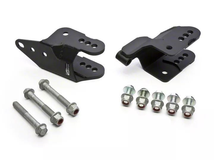
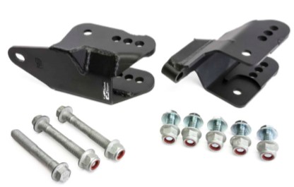
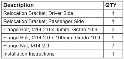
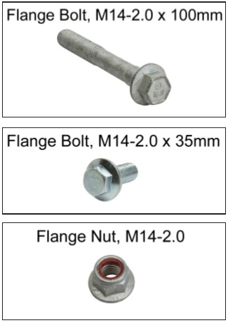
This Kit Contains
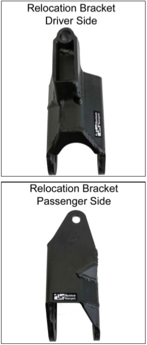
Component Identification
How to Choose the Control Arm Mounting Hole
WARNING: To get maximum performance from the MM Rear Relocation Brackets, complete this section before continuing.
IMPORTANT: If your Mustang has an aftermarket upper control arm with geometry different from the car’s stock geometry, you will need to determine that geometry. Most aftermarket upper control arms with different geometry can also be adjusted to match the stock geometry. Having the upper arm adjusted to match one of the two stock upper arm geometries will make setting the lower control arm bolt location much easier. You may need to contact the manufacturer of the upper arm to find out what the geometry is. Upper arm geometry that is different from stock will require more measuring and calculation- see the FAQs and Tech Tips section on the MM website.
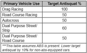
The MM Relocation Brackets provide multiple mounting locations for the axle-end pivot of the rear lower control arms. The mounting hole used determines the angle of the lower control arm. That angle, along with the angle of the upper am, determines the location of the rear suspension’s Instant Center (IC). The IC location is needed to determine the anti-squat percentage. The anti-squat percentage you want for your Mustang will direct you to which mounting hole to use. The appropriate anti-squat percentage depends primarily on how you use your Mustang. To learn more about the Instant Centers and anti-squat, see the FAQs and Tech Tips section of the MM website.
A. Use this table to find our recommended target anti-squat percentage for how you drive your Mustang.
B. On level ground, set the car at the desired ride height.
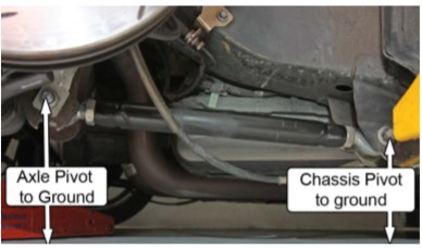
C. Measure the distance from the ground to center of the passenger side rear lower control arm mounting bolts. These measurements will be used to determine the correct mounting hole position to use on the relocation brackets.
D. Subtract the axle pivot bolt height from the chassis pivot bolt height. It’s important to keep track of whether the value of the difference is positive or negative. Example: If the axle bolt is higher off the ground than the chassis bolt, the difference’s value will be negative.
The Math:
Chassis Pivot Bolt Height – Axle Pivot Bolt Height = Pivot Bolt Difference
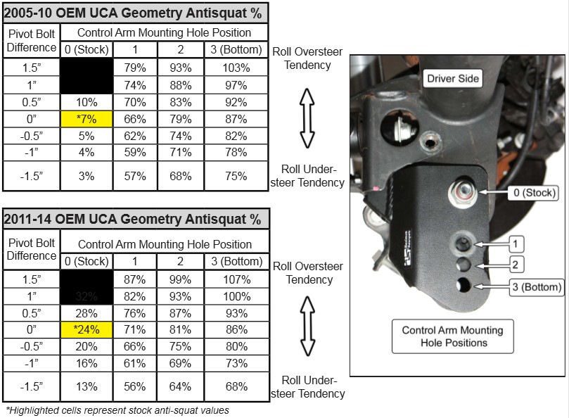
E. Look up the Pivot Bolt Difference in one of the two tables below. Which table to use depends on what your upper arm geometry is. One table is for Mustangs with the stock upper arm geometry of the 20052010 models. The other table is for Mustangs with the stock upper arm geometry of the 2011-2014 models. Use the table appropriate for your Mustang. See below for tables.
F. Find the listed Pivot Bolt Height Difference closest to the Height Difference calculated for your Mustang, in one of the two tables below.
G. Locate the horizontal row with the Pivot Bolt Height Difference closest to the Height Difference you calculated for your Mustang.
H. Look along the row to the right, and find the cell with the percentage value listed that is closest to your chosen target anti-squat percentage.
I. Look at the top of the column for that cell. There you will find the number of the hole where the control arm bolt needs to be to provide the Anti-squat percentage listed in that cell.
NOTE: On the right side of each table is an indication of what the roll steer tendency will be. Roll steer changes with the angle (from horizontal) of the lower control arms.
Installation
1. Complete the “How to Choose the Control Arm Mounting Hole” section at the beginning of these instructions.
2. Raise the rear of the vehicle and support it safely on jack stands.
3. Block the front tires to prevent rolling.
4. Remove the rear wheels.
5. Release the parking brake.
6. Remove the 4 nuts holding the rear sway bar to the axle using a 15mm deep socket.
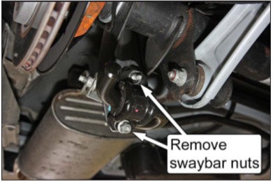
7. Move the rear sway bar rearward.
Passenger Side Preparation
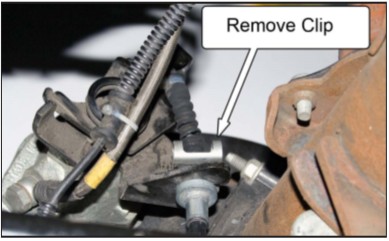
8. Remove the C-clip retaining the end of the parking brake cable housing to the caliper.
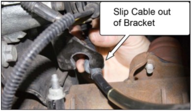
9. Pull down on the end of the parking brake cable housing and slide it rearward until it disconnects from the brake caliper.
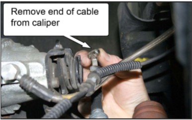
10. Unhook the parking brake cable end from the caliper.
11. If using a stock control arm, loosen the chassis end and axle end rear lower control arm mounting bolts using an 18mm socket. If using an aftermarket control arm, only loosen the axle side mounting bolt.
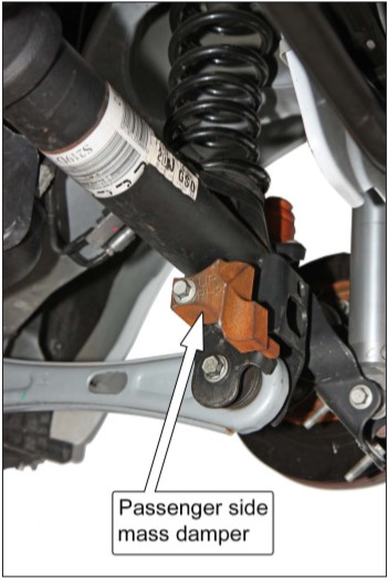
12. If present, remove the axle housing mass damper using a 15mm socket.
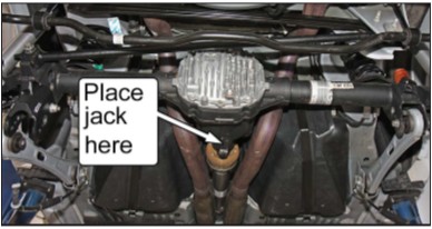
13. Support the center of the differential with a floor jack. The jack should lightly contact the nose of the differential to stop it from rotating when the control arm bolt is removed in the following step.
14. Remove the mounting bolt connecting the control arm to the axle housing.
NOTE: Raising or lowering the floor jack slightly will aid removal of the mounting bolt.
15. Lower the control arm and let it hang loose for now.
Passenger Side Relocation Bracket Installation
16. Slide the passenger side MM Relocation Bracket onto the stock control arm mounting bracket.
NOTE: It may be helpful to squeeze the stock control arm mounting bracket together with a large pair of pliers while sliding on the bracket.
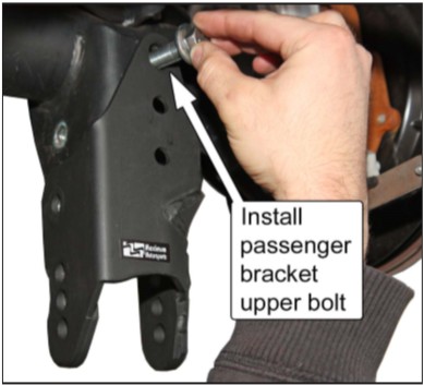
17. Take one of the provided 35mm-long flange bolts and insert it through the rear upper mounting hole in the MM Relocation Bracket. Secure the bolt using one of the provided 14mm flange nuts. Do not tighten yet.
18. Take two more of the provided 35mm-long flange bolts and insert them through the stock control arm mounting holes. Insert them from the inside out, so the heads of the bolts will be against the inboard side of the stock control arm mounting brackets. Install two more flange nuts on those bolts as well, but do not tighten them.
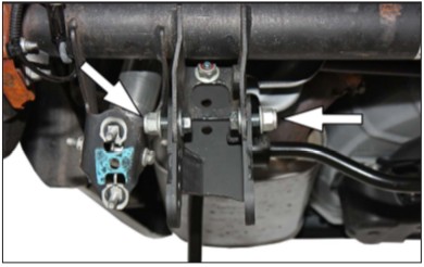
19. Torque the upper bolt installed in Step 17 first, then the two side bolts from Step 18. Torque all three bolts to 175 Nm (129 lb-ft).
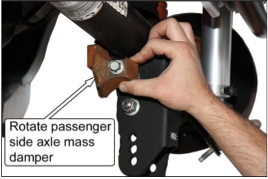
20. If retaining the axle mass damper, reinstall it at this time. It will be necessary to rotate it 180° from its original mounting orientation so the antirotation tab sits in the front of the stock control arm mounting bracket. Torque the mounting bolt to 90 Nm (67 lb-ft).
Driver Side Preparation
21. Remove the C-clip retaining the end of the parking brake cable housing to the caliper.
22. Pull down on the end of the parking brake cable housing and slide it rearward until it disconnects from the brake caliper.
23. Unhook the parking brake cable end from the caliper.
24. If using a stock control arm, loosen the chassis end and axle end rear lower control arm mounting bolts using an 18mm socket. If using an aftermarket control arm, only loosen the axle side mounting bolt.
25. If present, remove the axle housing mass damper using a 15mm socket.
26. Remove the mounting bolt connecting the control arm to the axle housing. NOTE: Raising or lowering the floor jack slightly will aid removal of the mounting bolt.
27. Lower the control arm and let it hang loose for now.
28. Remove the driver side Panhard bar mounting bolt using an 18mm socket. Retain the flag nut for later use.
Driver Side Relocation Bracket Installation
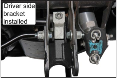
29. Slide the driver side MM Relocation Bracket onto the stock control arm mounting bracket.
NOTE: It may be helpful to squeeze the stock control arm mounting bracket together with a large pair of pliers while sliding on the bracket.
30. Take one of the provided 100mm-long flange bolts and insert it through the mounting hole for the Panhard Bar. Reuse the flag nut removed in Step 28 and thread the bolt into it, making sure the flag is pointed downward toward the ground. Do not tighten yet.
31. Take two more of the provided 35mm-long flange bolts and insert them through the stock control arm mounting holes. Insert them from the inside out, so the head of the bolts will be against the inboard side of the stock control arm mounting brackets. Install two more flange nuts on those bolts as well, but do not tighten.
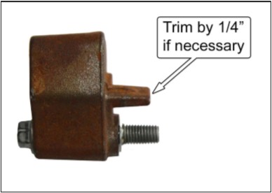
32. If reinstalling the axle mass damper, the antirotation tab must be trimmed 1/4” shorter at this time. Mark a line across the tab 1/4” away from the end, and trim using a hacksaw or other proper cutting tool.
33. If reinstalling the axle mass damper, do so at this time and torque the mounting bolt to 90 Nm (67 lb-ft).
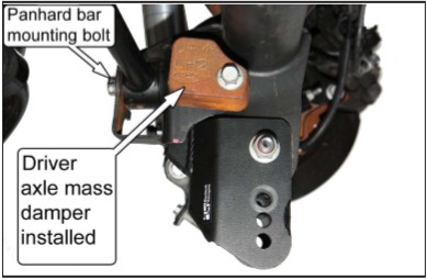
34. Torque the Panhard Bar mounting bolt first, then the 2 side bolts from Step 31. Torque all three bolts to 175 Nm (129 lb-ft).
Control Arm Installation
35. Raise the control arms into the mounting hole position determined from the “How to Choose the Control Arm Mounting Hole Position” section and install one of the provided 100mm-long flanged bolts from the inboard side of each relocation bracket.
NOTE: Raise the floor jack to rotate the pinion up so the mounting holes in the relocation bracket will align with the control arm mounting hole.
36. Install the remaining 2 provided 14mm flange nuts. If using aftermarket control arms, torque the bolt to the manufacturer’s recommendations. If reusing the stock control arms with rubber bushings, wait until Step 41 to torque the bolts.
NOTE: Stock control arms with rubber bushings must be torqued at ride height to prevent preloading the bushing.
37. Reinstallation procedures for the parking brake cables are opposite that of the removal procedures. Reinstall the parking brake cables at this time.
38. Reconnect the rear swaybar to the axle mounting brackets and torque the mounting nuts to 70 Nm (52 lb-ft) using a 15mm-deep socket.
39. Reinstall the rear wheels and lower the car safely to the ground.
40. Torque the wheel lug nuts to the manufacturer’s specification.
41. (Stock Control Arms) With the vehicle at the desired ride height, torque the rear lower control arm mounting bolts at the chassis and axle end to 175 Nm (129 lb-ft).
42. Test drive and enjoy!
