FREE 1 to 3-Day Delivery on Orders $119+ Details
Best Sellers


How to Install Scott Drake Bumpsteer Kit (05-10 All) on your Ford Mustang
Installation Time
1 days
Tools Required
- 8mm, 12mm, 19m & 21mm Wrenches
- 19mm & 22mm Sockets
- Ball Pean Hammer
- Measuring Tape
- Torque Wrench
- Aluminum Anti-Seize
- Alignment Rack with Turn Tables
- Gloves
- Safety Glasses
- Jackstands (If you are not using a lift)
Component List:
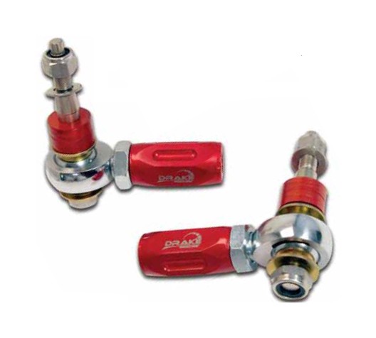
Bumpsteer Tie Rod Adjuster (5R3Z-3A130-BL)
• (2) Bumpsteer Tie Rod Ends
BUMPSTEER DEFINED:
Bumpsteer is the change in toe angle of the wheel as the suspension travels in jounce or rebound. This gives a feedback to the driver of the vehicle steering in any situation the suspension is moving including brake diving, hitting a bump, or in roll. Bumpsteer is an effect caused from the relationship between the geometry of the suspension and steering causing the tire to toe-out or toe-in when the suspension moves. Minimizing bumpsteer is typically desired to prevent the vehicle from unwanted steering without input from the driver.
Most modern front suspensions are either a short-long arm or strut type (as in the Mustang) that does not travel straight up and down, but in an arc. The center point of this arc (called instantaneous center) moves with suspension travel. The steering tie rod also travels in an arc with a fixed center driven by the steering rack arm inner pivot. In order to minimize bumpsteer these arcs need to be as coincident as possible at ride height with little change through the suspension travel. OE designers minimize bumpsteer for factory settings, but when any suspension points or ride height is changed, these arcs start to diverge and bumpsteer becomes pronounced.
In order to correct bumpsteer, the steering rack or outer pivot point on the upright need to be moved so that steering arc again is sweeping in the same path as the suspension arc. Due to packaging and geometry restraints, moving the outer pivot point is the most effective. With lowered vehicles, the outer pivot will need to be lowered so that the steering rack shaft is parallel with the lower control arm. This is done by using a bumpsteer tie rod adjustment kit that has shims for fine tuning the pivot location of the outer tie rod to minimize bumpsteer.
WARNING! Installation of this kit requires above average mechanical skills. This procedure should only be undertaken by a competent individual with the necessary skills to properly complete the installation. We strongly recommend that a factory workshop manual be available for reference during the installation. If you are not confident you can complete the job safely, have the work performed by a certified technician who is familiar with the suspension of a Mustang. Failure to reassemble the suspension properly can lead to serious injury.
Installation:
1. Raise vehicle and remove two front wheels.
(Make sure to use jack stands if you are not using a lift.)
2. Remove OE Tie Rod ends.
Loosen Jam Nut using a 21mm wrench on the jam nut and a 12mm wrench on the steering shaft. Only back nut off from tie rod enough to release tension. (About half a turn.)
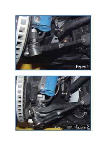
Loosen top nut securing shaft to upright using a 19mm wrench on the nut but do not completely remove. Tap on side of upright where the stud of the tie rod mounts while pulling down on tie rod to release the tapper seat. (See figure 1and 2)
Remove top nut and unscrew tie rod from steering rack shaft while holding steering shaft with a 12mm wrench to prevent it from spinning.
Repeat steps for other side.
3. Install Drake Automotive Group Bumpsteer Tie Rod End
Measure distance from end of steering shaft to jam nut. Move factory jam nut outward to reduce this distance by 3/16” to get a decent starting point for toe.
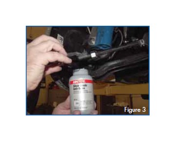
Apply anti seize to threads of the steering shaft since bumpsteer tie rod adjusters are aluminum. (See figure 3)
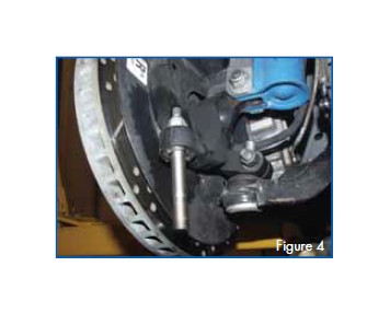
Remove tapered pin from assembly and insert into upright. Install supplied top nut and washer with a 19mm wrench on the nut and the box end of a 8mm wrench on the 12 point part of the stud to prevent it from rotating as you tighten. Use 19mm socket and Torque to 59 ft-lbs. (See figure 4)
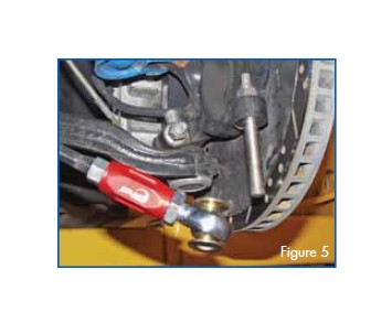
Thread bumpsteer tie rod end onto steering shaft until it seats against jam nut placed in previous step. NOTE: Rod end and jam nut on bumpsteer tie rod end are thread locked in place and are not intended to be moved or adjusted! (See figure 5)
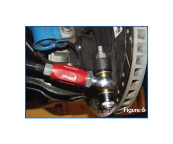
Add spacers, safety washers and rod end onto the bottom of the tapered shaft. At this point we are only going to be able to get close with the placement of the spacers. To get close try to align the steering shaft to be parallel with the lower control arm by putting the spacers either on top or bottom of the safety washers to move the rod end up or down. Add nylon nut to the bottom of the shaft. Use a 22mm socket and torque nut to 45 ft-lbs. The safety washers must always be on top and bottom of the rod end and then the spacers. (See figure 6)
Jam factory steering shaft nut to aluminum adjustment sleeve of the bumpsteer tie rod end while securing the steering shaft with 12mm wrench to prevent rotation.
Repeat steps for other side of vehicle.
4. Bring car to alignment shop and re-align to adjustment method below.
Put vehicle on alignment rack with turn tables for the front wheels and set the toe so both tie rods are symetric in position. Final toe will be set later.
Compress the susupension a minimum of 1 inch. Typically this is done using a winch or come-along secured to the floor pulling on the front crossmember. Once the suspension is compressed, measure the ride height. Take note of this figure and location of measurement since you will have to compress to this same height later.
Read the toe and the new compressed height and again at the uncompressed static height. Compare the two readings. Ultimately the goal is to achieve the smallest possible change in toe between the at-rest and compressed suspension height or, in other words, the least amount of bumpsteer in this range. Rearrange shims to the top or bottom of the rod end’s safety washers to change the pivot height of the rod end relative to the upright.
Repeat steps above. This will be a process of trial and error until the smallest possible toe change is achieved. It will be nearly impossible to achieve zero toe-change. It is better to arrange the shims so that the wheels toe in under compression versus out.
IMPORTANT: Make sure to compress the suspension the same amount each time. Also make sure to record the at rest and compressed readings for each shim change. Do not directly compare readings with previous shim setups as both static and compressed toe readings will differ each time the shim stack is rearranged. At this point we are only comparing the toe change (difference between static and compressed) due to suspension movement NOT the individual toe readings.
Once the optimal position is determined, reset the static toe to the desired setting. Typical setups use 1/16” total toe in.
Tips to achieve optimal setting quicker:
Vehicles equiped with factory K-member, upright, and balljoints will most likely have a setting with the rod-end closer to the top of the stud and more spacers at the bottom.
Vehicles using the Drake Automotive Group tall ball joint will most likely have a setting with the rod end closer to the bottom of the stud and more spacers on the top.
If caster/camber plates are used take note that increased caster will raise the outer tie rod thus requiring more spacers to be added above the rod end to compestate by lowering the steering pivot.