FREE 1 to 3-Day Delivery on Orders $119+ Details
Best Sellers


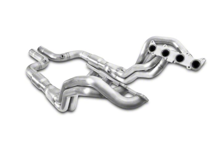
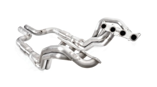
How to Install Stainless Works 1-7/8 in. Long Tube Catted Headers - Aftermarket Connect (15-17 GT) on your Ford Mustang
Shop Parts in this Guide
Thanks for purchasing Stainless Works headers for your 2015 Mustang GT 5.0. We have gone to great lengths to make sure that our exhaust systems fit and sound great. Please follow these steps to ensure that your installation goes as planned.
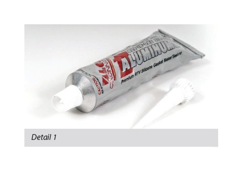
1. Stainless Works recommends the use of Permatex Hi-Temp RTV silicon gasket maker as an option to or in conjunction with the use of factory gaskets. The recommended RTV is Valco All-in-one Aluminum Sensor-Safe silicone.
2. Disconnect the battery before starting work on the exhaust system for your vehicle. Reconnect the battery when the job is completed.
3. Your exhaust system can be installed by a weekend warrior but the use of a lift is recommended for ease of installation. If using a jack, the vehicle must be placed on a level hard surface and jack stands are required for safety reasons.
4. Raise and support the vehicle.
DISASSEMBLY
5. Remove the battery box cover - 3 push clips.
6. Disconnect the battery.
7. Remove 6mm battery hold down bolt and remove the battery.
8. Remove (3) 6mm bolts holding the battery box in and remove the battery box.
9. Starting from the right side of car remove (6) push clips holding the windshield wiper cowl down.
10. Remove the inner battery box panel - (8) 6 mm bolts and (2) 8 mm bolts.
11. Loosen the air box clamp and disconnect the wire.
12. Remove the air box cover and filter.
13. Remove the air box - (1) 6 mm bolt.
14. Remove the lower engine service cover (2) 6 mm bolts and (4) screws.
15. Mark and remove the steering shaft from the rack by removing 8mm Torx bolt from top side of swivel joint.
16. Remove the wires from the starter (1) 8 mm nut, (1) 6 mm nut, then remove the starter - (3) 8 mm bolts.
17. Remove O2 sensors from the pipes or disconnect the pipes and remove the O2 sensors after the pipes are removed from the car. Mark the sensors with the correct locations for all four: left/ front, right/front, left/rear, right/rear so these are reinstalled correctly.
18. Raise up the motor slightly with a jack.
19. Remove the right motor mount - (3) 10mm nuts (4) 10mm bolts.
20. Remove (16) 10 mm nuts – (8) per side- from the manifolds and remove the manifolds and catalytic converters (all can come down all together).
21. Remove (16) 10 mm studs from the cylinder heads.
22. With the manifolds out, remove the left front O2 sensor wiring from its loom clips (so it will reach the longer position required for install) and remove the left rear one from the front loom clip on the side of the transmission. (You do not need to use the provided O2 extensions for a car with an automatic transmission - pulling the wires down from the loom clips will allow them to reach.) Note: manual transmission cars will utilize the provide O2 extensions – one on each side going into the header collectors (front). Install these now.
ASSEMBLY
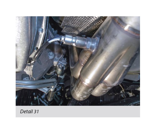
23. Note: Before installing the passenger side header, check the bolt holding the bracket for the A/C line. You may need to remove this bolt and zip tie the A/C line up and out of the way. Otherwise there may be a clearance problem with this bolt and the header primary tube.
24. Seal and install headers from the bottom using either the 10 mm bolts supplied or the factory studs and nuts.
25. Reinstall the motor mount and lower the motor and tighten.
26. Put the starter back in and tighten.
27. Reconnect the steering shaft.
28. Reinstall the engine service cover.
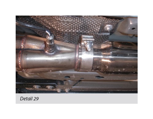
29. Install either the purchased catalytic converters or off road pipes using (2) 3” clamps.
30. Install the lead pipes using (2) 3” clamps.
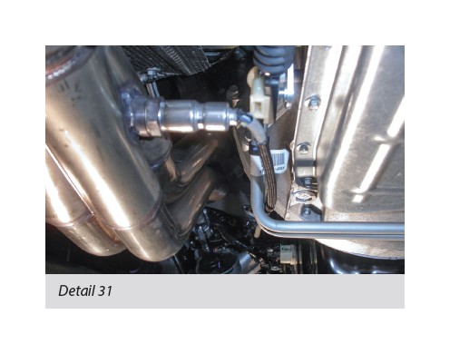
31. Reinstall O2 sensors in both the collectors and the lead pipes.
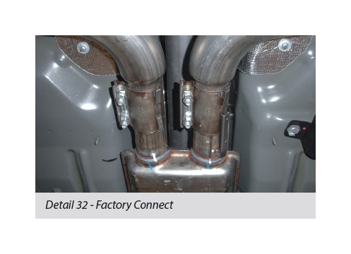
32. For Those Using Factory Connect Headers: the lead pipes hook to the factory exhaust, necking down at the factory break point.
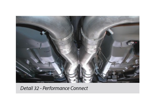
For those using Performance Connect headers: the leads are designed to mate to our catback for a full 3” system.
For those using Aftermarket Connect (part numbers M15H3CATLG and M15H3ORLG)
Connecting MBRP 3” Catback System: the MBRP catback system is cut at necked down point allowing the header leads to slide over making a full 3” system.
Connecting Corsa Catback system: Stainless Works header leads are cut at expansion point, and Corsa Adapters are discarded, making a full 3” system.
Convert SW Factory Connect Catback To Full System: Cut SW Catback system at necked down point which allows leads to slip over, making a full 3” system.
33. Adjust everything for fitment and tighten all clamps.
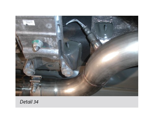
34. Be sure to have adequate clearance around all wires, hoses and lines. If anything is in contact with the exhaust system, it will melt. Make sure to have at least ½” of clearance and wrap any suspect areas with DEI thermal barrier wrap.
35. Lower the vehicle.
36. Reinstall the air box.
37. Reinstall the battery box components removed and reinstall the battery.
38. After double checking for clearance and making sure all lines, wires and hoses are secured, drive the car for 10-20 miles and re-check all clamps and clearances. Your system may be tack welded at the joints/ clamps to reduce shifting of the system during heating and cooling cycles. Make certain to disconnect the battery before performing any welding.