FREE 1 to 3-Day Delivery on Orders $119+ Details
Best Sellers


How to install a Hellion Twin Turbo on your 1996-2004 Mustang
Shop Parts in this Guide
Installation
- Disconnect battery and elevate front end of car on either Jack stands or a lift if available
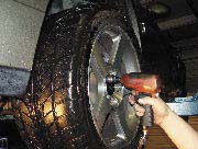
- Lock steering wheel and remove key, then remove front tires and wheels
- Remove sway bar assembly
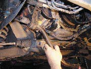
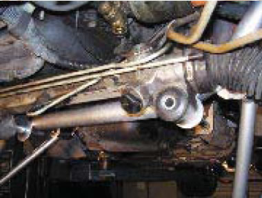
- Remove steering shaft bolt
- Remove rack bolts
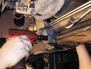
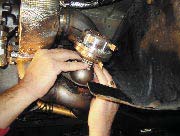
- Remove steering tie rod ends (you may want to try using an air hammer with a pickle fork to remove the tie rod end if it is diffi cult to remove)
- You may need to loosen and remove engine mount bolts and raise drivers side block to clear steering lines from oil fi lter boss
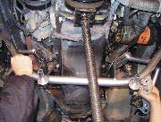
- Pry rack from K-member
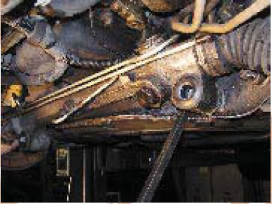
- Strap rack to front cooler
- Remove brake calipers left & right
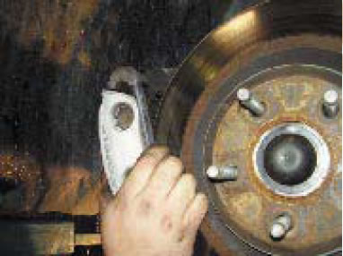
- Remove both front discs
- Remove ABS sensor lines both left and right
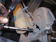
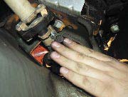
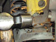
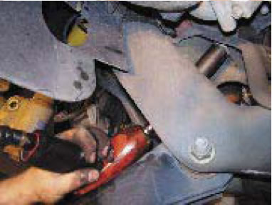
- Loosen lower ball joint 15/16 nut (both left and right) until there is a 1/8 inch gap with the nut maintaining full thread engagement.
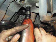
- Use an air hammer or electric hammer with a pickle fork in order to disengage ball joint from spindle
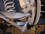
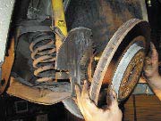
- Support A-arm with jack to take load off of spring and remove the 2 strut to spindle bolts, then lower Aarm, being cautious because spring is under pressure.
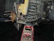
- Remove spindle, both left and right
- Remove left and right motor mount nuts
- Support engine and transmission with appropriate upper support tool or support from beneath.
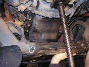
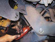
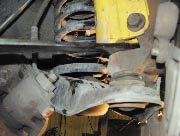
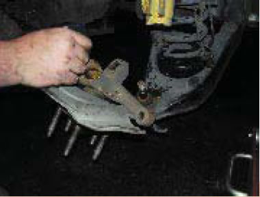
- Support K-member and remove K-member bolts (6) attaching K-member to frame.
- Remove old K-member
- Remove factory O2 sensors (4)
- Remove ground strap on drivers side frame rail and remove Oil fi lter
- Raise new K-member into place, re-install the 6 K-member bolts that attach K-member to frame. Make sure that the brake lines are not between K-member and frame.
- Tighten bolts to 66 ft. lbs for the lower bolts, and 85 ft. lb.s for the upper bolts.
- Install bushings and sleeves into tubular A-arms, making sure that the short sleeve is in front, and the long sleeve in back
- Install a-arms using supplied bolts and tighten to 148 ft. lbs.
- Install motor mounts nuts and tighten to 110 ft. lbs.
- Install grease boots on lower ball joints
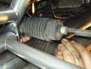
- Install steering rack, install rack bolts and tighten
- Re-install steering knuckle and tighten
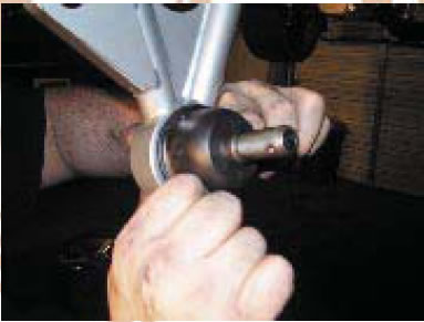
- Remove factory caster/camber plates by removing the 3 nuts on each side
- Remove plate from strut by removing large nut on top of strut shaft
- Install new caster/camber plates
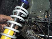
- Install strut with coilover kit into caster/camber plate, using caster camber instructions as reference for bearing/shim stacking order.
- Re-install factory spindle and hub assembly and retorque to factory specs
- Re-install factory ABS sensor, steering linkage, brake rotor, and calipers
- Re-install Sway bar and end links, re-install ground strap to frame using supplied self-tapping screw, and install supplied oil fi lter.
- Remove left and right side splash guards
- Remove screws that hold inner fenderwell to front fascia
- Remove 4 nuts holding front fascia to fender
- Disconnect fog lights
- Remove 2 lower push pins that hold fascia to lower radiator support
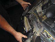
- Disconnect and remove headlights by removing headlight straps (4 total, 2 per side) and pulling headlights straight out.
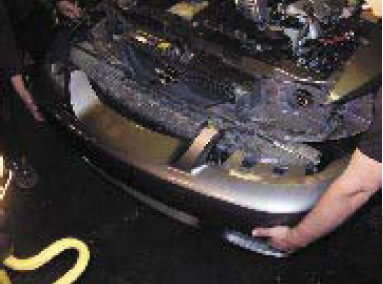
- Remove front fascia and remove radiator core support cover
- Remove foam bumper insert by pulling straight off.
- Remove left and right forward splash guards
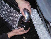
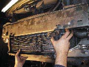
- Remove lower, passenger side intercooler hose and drain aftercooler system
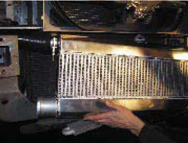
- Disconnect aftercooler hard line from front of heat exchanger
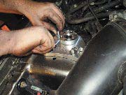
- Remove factory heat exchanger and set it aside for re-assembly later
- Disconnect 2 clamps and hoses between pump and engine hard lines
- Unbolt and remove factory aftercooler water pump and set it aside for later use
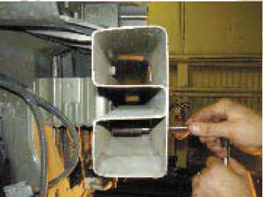
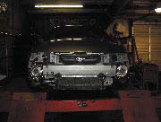
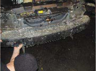
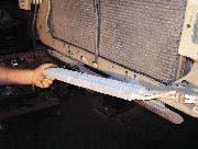
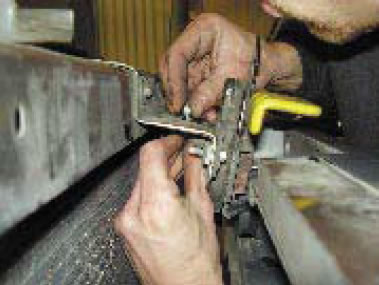
- Mark both ends of bumper with lines marking where the bumper support lip ends
- Remove bumper from vehicle for cutting
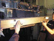
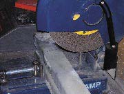
- Cut marked ends of bumper off, and de-bur
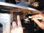
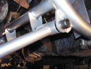
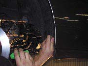
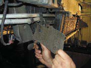
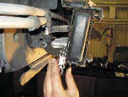
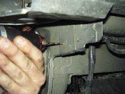
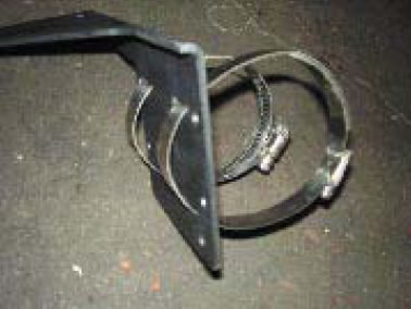
- Take turbo support bracket and position on radiator support. Mark holes and drill with a .310 bit (2 bits may be necessary for drilling, a smaller bit to start the hole, and a larger bit to fi nish drilling, also if a 90 degree drill, either air powered or electric is available for use, it can make this process easier.
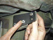
- Bolt plates to radiator support using supplied 5/16 x ¾ long bolts, nuts, and washers.
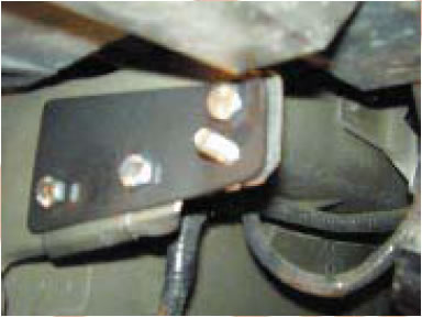
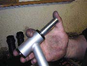
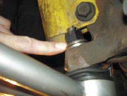
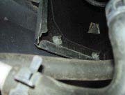
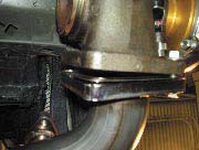
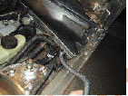
- Insert 1 ¼” long bolt from rear to front as shown
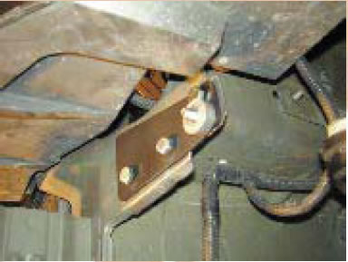
- Slide supplied aluminum spacer over bolt as shown on both sides
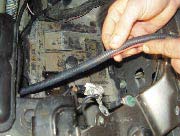
- Remove factory hood latch support rod
- Unbolt power steering cooler and let hang
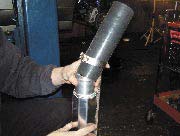
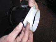
- Install 9” silicone hose with clamp onto intercooler and tighten, repeat this process with both the 3” and 2.5” silicone hose
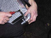
- Install intercooler support strap with supplied bolt and nut
- Install intercooler
- Bolt intercooler to lower radiator support using supplied M6 bolt and nut
- Bolt intercooler support strap to top of cooler using supplied bolt & nut
- Re-attach power steering cooler to radiator support
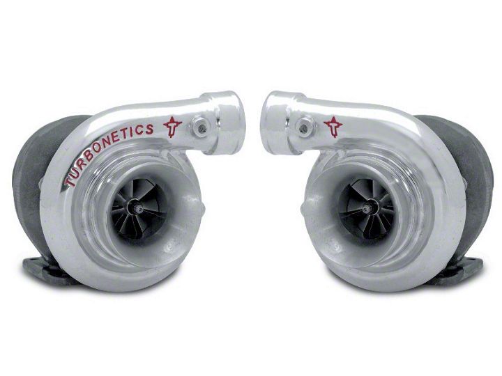
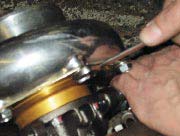
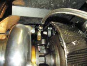
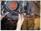
- Loosen turbo clocking bolts (6 per side)
- Clock turbo according to picture ( Turbo clocking may need to be adjusted several times for proper fi tment)
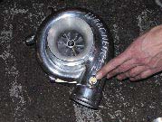
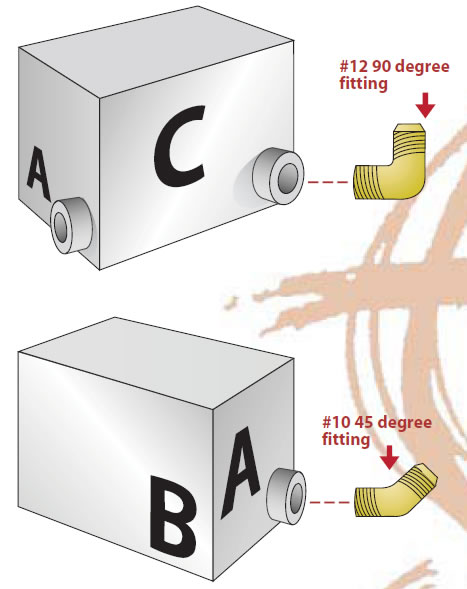
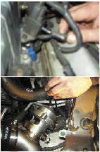
- Install 90 degree wastegate fi tting into compressor cover. (Fitting is located in wastegate box)
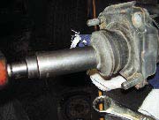
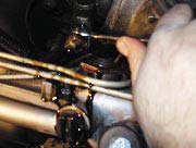
- Install oil feed fi tting using thread sealant
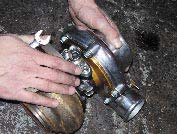
- Install 45 degree oil drain fi tting using thread sealant. NOTE: When installed on the vehicle, the oil feed and drain fi ttings must be vertical for proper function.
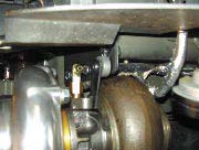
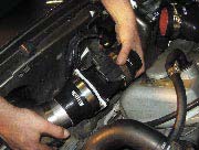
- Insert passenger side compressor housing discharge into intercooler end, making sure to slide the clamp on first
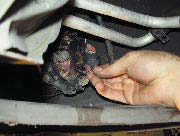
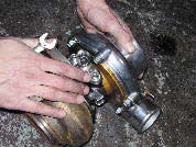
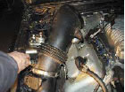
- Install turbo support strap over bolt with spacer, then install nut. There are 3 support straps included, each with varying lengths to accomodate for different chassis. start with the shortest strap, and install different straps until the fit is satisfactory. The turbine housing will need to be turned to remove the bolt in order to sandwich the strap. After bolt is re-installed, rotate turbine to shown position and then tighten all bolts. (Repeat on drivers side)
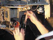
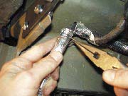
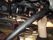
- Wrap driver and pass. side wiring harnesses with supplied heat wrap and secure with supplied stainless wire. Repeat this step on the other side, and also make sure to wrap horn with protective wrap also
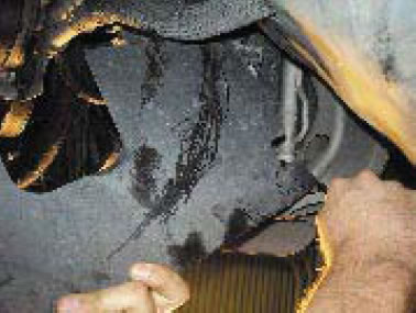
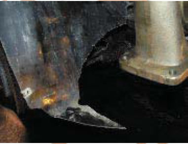
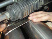
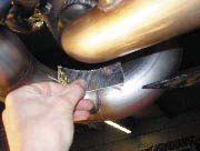
- Trim driver and pass. side wheel well liner as shown
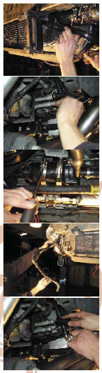
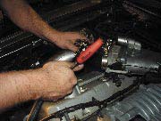
- Install pass side HTT-2 turbo inlet making sure that the gasket from the factory manifold to the pipe is installed, it may be necessary to raise the A-arm with a jack in order for this pipe to clear, but please note that the only time that these two pipes will have close contact is when the car is in the air, this clearance will NOT be an issue during normal driving.
- Install factory manifold nuts
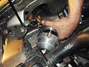
- Insert stainless turbo gasket in between turbo and uppipe and install (4) 1 ½” long x 3/8” hex bolts and snug. –NOTE-- Do NOT tighten anything fully yet, as this may make aligning the kit piping diffi cult later on, once kit is fully installed, tighten everything up
- Repeat pipe installation on drivers side
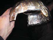
- Install heat shield on turbo, shield may need to be cut and trimmed in order to attain a proper fi t
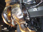
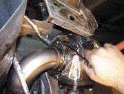
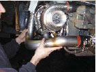
Install 3” downpipe with supplied 3” V-band clamp, making sure that the V-band does not interfere with the heat shield, and is fully seated on the exhaust housing of the Turbo
- Install studs into wastegate
- Slide wastegate gasket over studs, only 1 gasket per wastegate
- Install studs on wastegate
- Install wastegate, making sure that none of the bolts bottom out on the lower pipe
- Install Fittings into wastegate (supplied in wastegate box_)
- Re-install O2 sensors
- Connect turbo kit to cat-back system
- Install 4x6” heat shields and secure to piping using supplied steel zip-ties, these ties will need to be doubled up in order to reach around tubing. –NOTE—This step must follow the installation of the cat-back system, otherwise lining up the cat-back with the piping will be very diffi cult
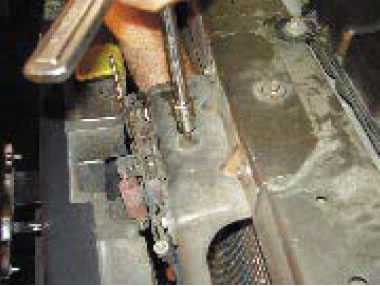
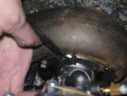
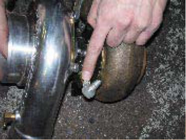
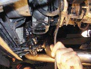
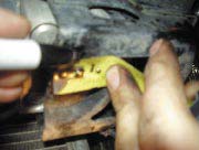
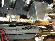
- Punch Oil pan using supplied punch and tap using the supplied tap coated with grease
- Install #6 to 3/8 pipe fi tting in pan using Tefl on tape to seal threads
- Remove coolant can support rod
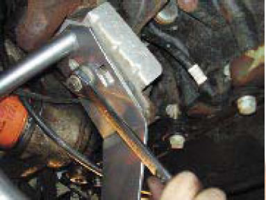
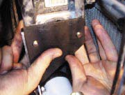
- Locate ABS bracket on the front part of the passenger side of the engine compartment. Measure ½” in from inner edge and mark
- Position oil pump mounting bracket and mark (2) holes ½” from edge
- Drill 2 5/16” holes in bracket, being careful not to harm the wires above the bracket
- Install supplied fi ttings with sealant on oil pump as shown
- Install supplied hose clamps through oil pump bracket
- Bolt oil pump to other side of bracket using supplied 10/24 button head bolts and nuts
- Bolt bracket to ABS bracket using supplied ½” long bolts and nuts
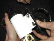
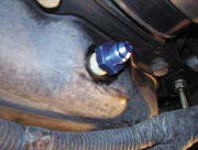
- Install fittings in oil catch can as shown using thread sealant to insure that there are no leaks
- Install can and attach to pump
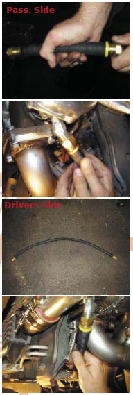
- Assemble turbo oil return lines, both drivers and passengers sides and attach to turbo and oil catch can
- Assemble the #6 line that connects the oil pump to the oil pan, connect and tighten
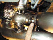
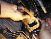
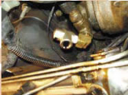
- Locate pipe port on oil fi lter housing and remove
- Screw 90 degree, ¼” pipe male fi tting into port using sealant
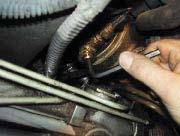
- Screw tee fitting into 90 degree fitting
- Install 90 degree and 45 degree fittings into tee using sealant
- Connect supplied oil feed lines from fi ttings to each turbo using the long line for the passenger side, route away from moving parts.
- Re-install bumper and factory heat exchanger
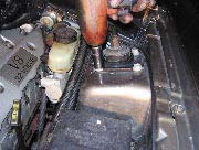
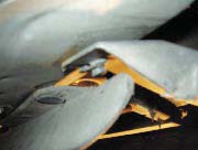
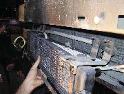
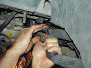
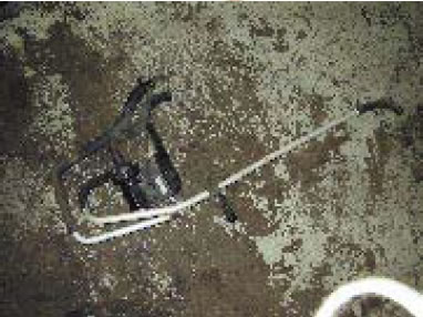
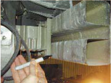
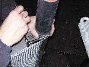
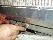
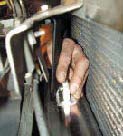
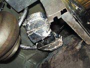
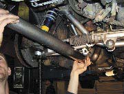
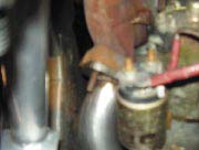
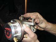
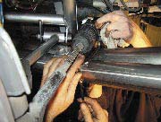
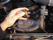
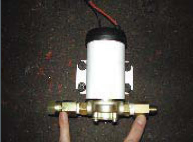
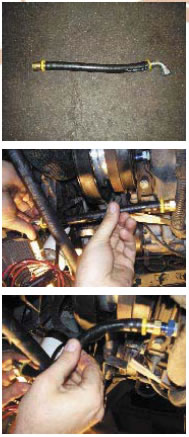
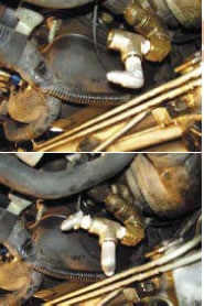
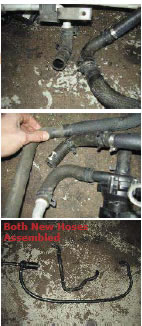
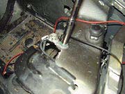
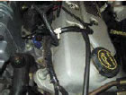
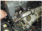
- In this step we are relocating the aftercooler pump to the new bracket.You will re-use some of the factory aftercooler water hoses. See pictures for assistance. Use the extra supplied hose and hose splices.
Shown are a factory hose setup as well as the new setup that will be used for the kit
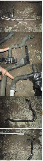
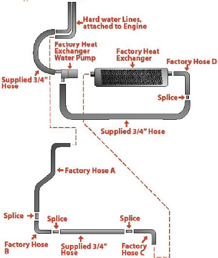
- Install hoses and clamps (see pictures)
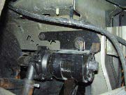
- Install pump into hose clamps and tighten
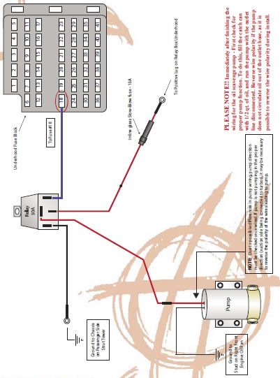
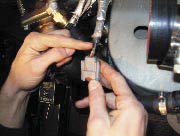
- Extend intercooler pump wire using supplied splices, wire, and plug in, making sure to use solder and shrink wrap on all connections.
- Ground oil pump and relay to ground on driver’s side radiator core support (refer to wiring diagram for assistance with wiring the pump. )
- Wire supplied fuse holder to fuse junction box next to battery
- Use supplied loom to cover wires
- Run supplied 22 gauge wire through fi rewall harness boot to fuse #18 and connect using supplied fuse tap making sure to solder all connections, then cover wire with loom, but do not allow wire to scuff on body around boot (use supplied fuses)
- Remove factory air inlet assembly, detach mass air meter
- Install intercooler pipe and connect to intercooler, secure with clamp
- Connect MAF adapter fl ange to mass air meter if you are using the factory air meter.
- Connect adapter hoses, re-install MAF meter
- Install polished throttle body inlet pipe into oval throttle body adapter tube and secure using the supplied clamps
- Reconnect MAF plug
- Attach bypass valve using supplied clamp
- Connect vacuum line from vacuum source to top of bypass valve
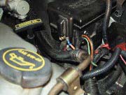
- Install 2 tees off of the fuel rail pressure sensor. One signal to feed the boost controller (if used), the other to connect to the bypass valve (see pictures)
- (Optional, but recommended) wrap boost pipe in heat wrap to reduce under-hood heat
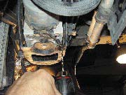
- Check that sway bar does not hit oil feed fi tting or oil fi lter housing by putting the cars weight on the wheels (the swaybar can swing back and possibly hit oil feed fi ttings).
Final Steps
- Change the oil
- Re-connect battery
- Test for oil pump operation by turning key to “ON” position , and check to see if pump is functioning, If it’s not, refer back to the wiring diagram and check all connections and fuses and replace or re-do if neccessary. -NOTE- Oil pump operation is critical. If the oil pump ceases function, sever problems can occur. In a vehicle with modifi cations such as this, it is imperitive that the operator regularly check for oil pump operation. If the system fails, bluish white smoke from the turbos will be a warning sign of possible damage to the system. If this occurs, stop vehicle immediately. You can call Hellion Power Systems at 505-873-4670 for technical assistance if a problem arises.
-Re- install factory bumper cover
- Check/ top off all fl uids
- Start car and let it idle for a couple of minutes while checking for any leaks or possible problems, fi x any leaks if found.
- Take car to a dynomometer facility and have it professionaly tuned as soon as possible to avoid any damage to the engine. DO NOT put vehicle under boost until it has been properly tuned by a professional.