 FREE 1 to 3-Day Delivery on Orders $119+ Details
Best Sellers


How to Install Maximum Motorsports Competition IRS Tie Rod Kit on your Mustang
Shop Parts in this Guide
Read all instructions before beginning work. Following instructions in the proper sequence will ensure the best and easiest installation.
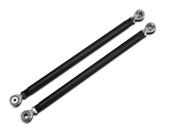
IRS Tie-rod and Bumpsteer Kit
The stock rear tie-rod is a weak link in the IRS suspension system. An IRS-equipped Mustang with only moderate performance upgrades can easily attain loads high enough to deform a stock tie-rod. When a rear tie-rod deforms, the rear toe angle changes, causing significant handling and traction problems. Even a drag race style launch can cause deformation, and failure, of the stock IRS tie-rod.
The robust MM Tie-rod is better able to handle the rigors of drag racing and open track use than the stock tie-rod because we designed it to be considerably stiffer than stock. It will not deform or fail as easily as the stock tierod.
Not Just a Stronger Replacement
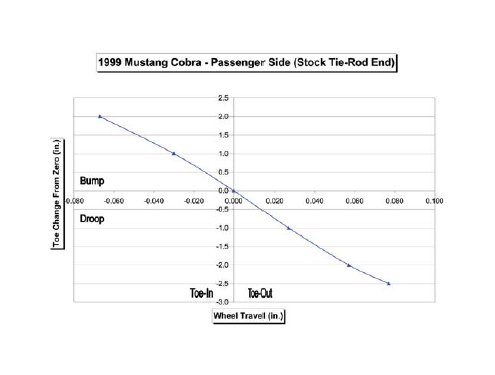
The MM Tie-rod kit is much more than just a stronger replacement for the stock unit. It has the additional benefit of providing a means to adjust bumpsteer. A Mustang equipped with IRS is more sensitive to rear bumpsteer than it is to front bumpsteer. Even very small changes in the toe setting of the rear suspension will cause the rear tires to begin steering the car. The result is excessive oversteer, instability, and asymmetrical handling characteristics. Just as with the front of a vehicle, making changes to enhance the performance of an independent rear suspension system will often require tuning the alignment. The handling of an IRS-equipped Mustang will benefit greatly from fine-tuning its bumpsteer characteristics.
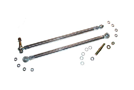
The MM IRS Tie-Rod Kit is designed to allow adjustment of the rear steering geometry to minimize the effects of bumpsteer. This kit includes the same tapered stud and adjustment shims for bumpsteer adjustment that are in our MMIRSTR-1 kit. However, this kit also provides the ability to adjust the height of the inner tie-rod pivot. That gives a wider range of bumpsteer adjustment possibilities, which is an advantage for Mustangs driven in serious competition.
2003-04 Cobra IRS
Starting with the 2003 model year Cobra, the vertical mounting position of the IRS inner tie-rod end was altered from its location in the previous years. The new position altered the bumpsteer curve. While this reduced the understeer of stock 2003-04 Cobras, there can still be problems once the vehicle’s suspension is modified. For earlier IRS Cobras, the simple fix of duplicating the 2003 Cobra bumpsteer curve becomes less and less desirable as the compliance of the OEM suspension is reduced. MM recommends matching the 2003-04 Cobra static bumpsteer curve only for cars that retain the original factory rubber bushings in the rear suspension.
For cars with any of the typical IRS performance upgrades, such as springs, IRS subframe bushings, or rear control arm bushings, as a starting point MM recommends that the rear bumpsteer curve be adjusted to minimize any toe changes with suspension movement. After testing the car with this baseline set-up, the handling balance should be fine-tuned by adjusting the rear bumpsteer curve. While MM can recommend rear alignment settings, only your continued testing will confirm what works best for your car and your driving style.
NOTE: You will need to have the rear toe setting professionally adjusted after installing this part.
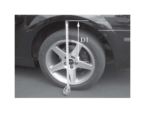
1. If you will be adjusting the bumpsteer, before jacking up the car measure the distance between the rear wheel’s hub center and the fender lip. This is your baseline ride height. Record this dimension for later use.
2. Jack up the rear of the car and place it safely on two jackstands. Position the jackstands under the chassis, not under the control arms.
3. Remove the rear wheels.
4. Support the control arm just above full droop with a jackstand. Starting on the driver’s side of the car, loosen and remove the lower shock mounting bolt. This creates room to move the tie-rod more freely.
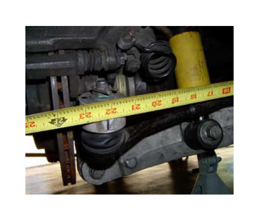
5. Make a vertical reference mark on the rear face of the steering arm. Take a reference measurement between the reference mark and a point on the tie-rod near it’s inner end, such as the tie rod mounting tab on the IRS sub-frame. Record this dimension, as it will be used later to adjust the length of the tie-rod.
8. Remove the nut securing the tie-rod end to the spindle. Apply penetrating oil to the tie-rod end where it comes through the spindle.
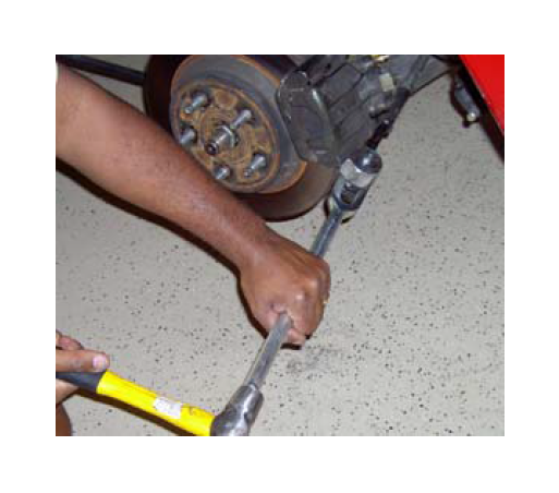
9. Using a suitable tie-rod end splitting tool, separate the outer tie rod end from the steering arm of the spindle. To avoid damage to the control arm, the tie-rod end splitting tool should be held at an orientation generally parallel to the axle centerline of the IRS.
10. Remove the bolt securing the inner tie-rod end to the IRS sub-frame and remove the factory tie-rod from the vehicle.
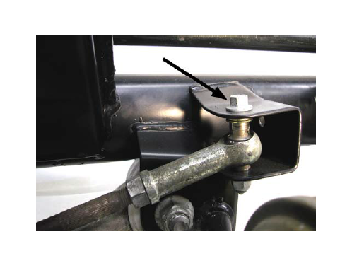
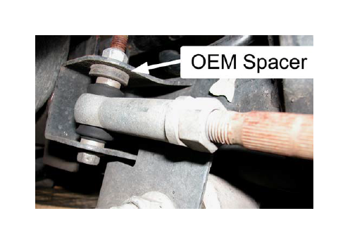
Note: 2003-04 cars have a factory spacer installed between the upper mounting tab and the tie-rod end crush sleeve. Keep this part. It will be re-used.
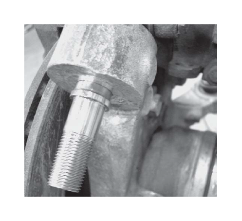
11. Install one of the supplied tapered studs through the steering arm of the spindle. Secure the tapered stud to the steering arm using one of the supplied washers and 1/2-20 lock nuts. Torque the lock nut to 50 ft-lbs.
Note: If the tapered stud spins while tightening the lock nut, thread the two supplied standard (non-locking) 5/8-18 nuts onto the lower portion of the stud and tighten them against one another. Hold the lower of these two jammed nuts while tightening the top lock nut and securing the tapered stud. Remove the two nuts after torquing the top locking nut.
Note: The shoulder of the tapered stud will not contact the bottom surface of the steering arm. The shoulder is designed to provide a stop for the spacers in your MM Kit. The tightly controlled taper dimensions (both on the Ford steering arm, and on the MM Tapered Stud) control how deep the stud sets into the tapered hole.
12. Slip the .060” thick spacer onto the bottom of the tapered stud. This spacer will make the bumpsteer curve approximately the same as the 2003 Cobra, which will be an improvement for 1999 cars. In the absence of measuring the bumpsteer on your car, MM recommends this bumpsteer geometry for cars retaining the rubber bushings in the rear suspension.
Note: To properly adjust the car’s bumpsteer curve will require use of an MM Bumpsteer Gauge. Use of this gauge will allow you to adjust the spacer stacks on your tie-rod ends to minimize bumpsteer effects. For cars that have had the factory rubber bushings replaced with urethane or Delrin, we highly recommend tuning the bumpsteer curve in this manner for best handling.
13. Slip the spherical rod-end of the tie-rod onto the stud.
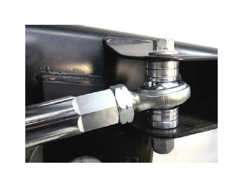
14. Install the tie-rod to the inner mount using 4 of the supplied .2” thick, 10mm ID spacers.
Note: If the lower shock mounting bolt is in the way, you may wish to remove it for easier installation.
Note: MM recommends a centered spacer stack (2 spacers above and 2 spacers below) as a starting inner-spacer configuration for 1999 IRS cars.
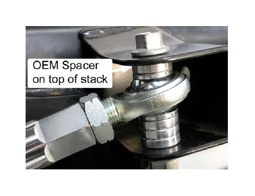
Note: MM recommends a spacer stack that is biased upwards (3 below, 1 above) as a starting inner-spacer configuration for 2003-04 IRS cars. Place the OEM Spacer on the top of the MM spacer stack (OEM Spacer not shown in photo).
Note: Raising the inner tie-rod pivot by placing additional spacers below the tie-rod end will have the same effect on bumpsteer as lowering the outer tie-rod end.
15. Slip the thickest of the remaining spacers onto the stud below the outer tie-rod end. This acts as a washer for the lock nut.
16. Thread the 5/8-18 locking nut onto the stud and torque to 65 ft-lbs.
17. Torque the inner tie-rod bolt to 35 ft-lbs.
18. Reinstall the lower shock mounting bolt, if previously removed. Torque to 98 ft-lbs.
19. Remove jackstand supporting the control arm, and allow the arm to sit at full droop.
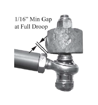
20. Check the clearance between the jam nut on the spherical rod end and the arm on the spindle. Make sure there is at least 1/16" clearance when the suspension is at full droop. If there is not, remove the tie-rod end from the stud, then loosen the jam nut and unthread the spherical rod end out of the aluminum sleeve to provide the clearance. The spherical rod end should not need to be unthreaded more than one or two turns. Re-tighten the jam nut.
21. The length of the tie-rod assembly is adjusted by rotating the tie-rod. Lengthen or shorten the assembly to match the dimension recorded in Step 5. Loosen the inner and outer tie-rod end jam nuts to adjust the tie-rod length.
22. Place the jack under the outermost portion of the control arm. Jack the control arm to ride height (as measured in Step 1.) If the car comes up off the jackstand before reaching ride height, stop there.
23. Snug the inner and outer tie-rod end jam nuts.
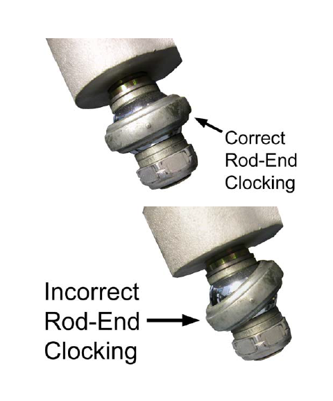
24. Make sure the tie-rod ends are clocked correctly to each other. Each spherical rod-end should be in the center of it’s range of rotation when the car is at ride height. They may not necessarily be in the same plane.
25. Tighten the tie-rod end jam nuts to 41 ft-lbs.
26. Repeat steps 3 to 25 on the other side of the car.
27. If you will be measuring and adjusting the bumpsteer, jack up the front of the car and place it safely on two jackstands so that the car is approximately level.
28. Disconnect the swaybar end links from the control arms.
29. The spring must be inactive on the side that you will be measuring bumpsteer. • If you have rear coil-overs, lower the rear lower spring perch. Be sure to count the number of turns so you can restore the ride height afterwards.
• If you car has a conventional spring, the spring can be compressed onto the control arm, but does not need to be removed.
• To do this, use an internal spring compressor hooked to the spring near its top, and hooked to the lower control arm through its center hole. Compress the spring down onto the control arm.
• Place a jack directly underneath the lower control arm’s outer pivot, at the spindle.
• Jack the control arm up until the hub center is the same distance below the fender lip that you recorded in step 1. This is your baseline ride height to start measuring bumpsteer.
• Refer to the instructions that came with your MM Bumpsteer Gauge to measure the bumpsteer curve. To maintain consistency in measuring the toe changes, always place the bumpsteer gauge’s dial indicator towards the rear of the car, and measure the vertical travel at the dial indicator.
• Depending on ride height, the Cobra IRS has approximately 2" of travel in both bump and droop.
• Measure and adjust the bumpsteer on both sides of the car. Do not be surprised if the required spacer stacks on each side of the car to achieve the same bumpsteer curves are different.
30. Reconnect the swaybar end links and torque to 35 ftlbs.
31. Reinstall the rear wheels. Torque the lug nuts to factory or wheel manufacturer’s specs.
32. Lower the car safely to the ground, and have the rear toe setting professionally aligned.
This kit includes:
2 Aluminum Tie-Rod with Spherical Rod-End &
Jam Nut, Assembled
2 5/8”-18 G5 Nut (for use in installation)
2 Tapered Bumpsteer Stud
8 Aluminum Inner Tie-Rod Spacer, .200” thick.
2 1/2” -20 G8 Nylock Nut
2 5/8”-18 G8 Nylock Nut
2 1/2” G8 Flat Washer
2 Bumpsteer Spacer - .24” thick
2 Bumpsteer Spacer - .12” thick
2 Bumpsteer Spacer - .06” thick
2 Bumpsteer Spacer - .03” thick
2 Bumpsteer Spacer - .015” thick
