Best Sellers
How to install a RAM Street Dual Disc Force 9.5 Clutch on your Mustang
Shop Parts in this Guide
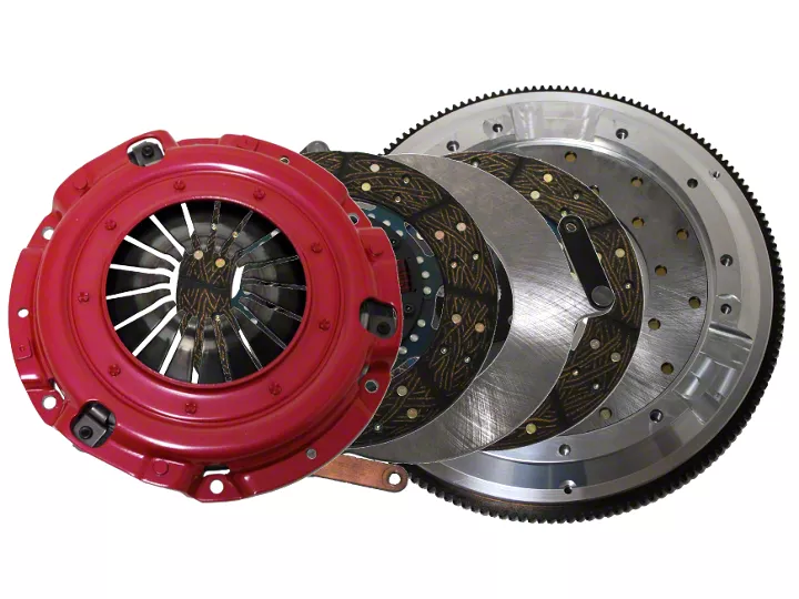
- RAM Clutches Force 9.5 300 Series Organic Dual Disc Clutch Kit with 8-Bolt Aluminum Flywheel; 23-Spline (11-17 Mustang GT; 12-13 Mustang BOSS 302)
- RAM Clutches Force 9.5 300 Series Organic Dual Disc Clutch Kit with 6-Bolt Aluminum Flywheel; 26-Spline (96-04 4.6L Mustang)
- RAM Clutches Force 9.5 300 Series Organic Dual Disc Clutch Kit with 8-Bolt Aluminum Flywheel; 10-Spline (99-04 4.6L Mustang)
- RAM Clutches Force 9.5 300 Series Organic Dual Disc Clutch Kit with 8-Bolt Aluminum Flywheel; 26-Spline (96-10 V8 Mustang)
Installation
Before installation
For 05-up applications, proper release bearing preloading is essential to operation of this clutch due to the hydraulic release mechanism. You MUST use the setup drawing located on the back of the quick start guide to check this before finishing the install. 2011 - up applications require removal of the factory slave cylinder spacer. Please see 'understanding factory hydraulics'.
Test fit both discs on the input shaft of the transmission. Make sure they slide freely on the splines.
If you are using an aftermarket bellhousing, it MUST be dial indicated to the engine before installing the clutch. These bellhousings typically are not centered and can cause release issues if not addressed. For 01-04 Mustang applications, it may be necessary to trim the input collar ½ inch to allow the transmission to fully install into the bellhousing without contacting the clutch disc.
For Mustangs utilizing a T-56 transmission with an aftermarket 26 spline input shaft, you must check to insure you have complete spline engagement on the bottom disc. Some older retrofit inputs have shorter splines and may not properly engage the bottom disc.
IMPORTANT TECHNICAL NOTE:
The 2010 GT500 uses a different slave release bearing and clutch than the 06-09 models. This one is shorter and has maximum travel of .880”. In order for our dual disc built at 3.300 – 3.400 to work with this car, the customer must install a 1/2 inch bearing spacer to achieve .530-.550 bearing preload. Without it there is NO preload and the bearing will damage itself if the install and bleed is attempted without verifying measurements.
Clutch installation
Remove the 6 pressure plate attachment bolts from the flywheel. Notice the proper orientation of the pressure plate on the flywheel. Be sure the unit is installed this way. Lift the cover from the flywheel. The top disc is a sprung hub configuration. After removing the sprung hub disc you will see the floater plate.
The floater plate drives off of the three straps mounted to the flywheel, which are bolted in position. This is how the floater should fit when installing the unit in the car.
Remove the three 5/16-18 capscrews and lift the floater plate out of the assembly. The solid hub bottom disc can now be removed.
Install the flywheel loctite or similar thread locker on the flywheel bolts. Torque the flywheel bolts to 75-85 ft/lbs.
Slip the top clutch disc (sprung hub disc) onto the clutch alignment shaft followed by the floater plate and bottom clutch disc (solid hub). Be sure the floater plate side that has the machined outer lip is facing the transmission (i.e. the completely flat side towards the flywheel).
Slide the clutch alignment tool into the pilot bushing while positioning the floater plate over the drive lugs. The three retaining straps should line up with the three 5/16-18 holes on the flywheel surface.
Install the three 5/16-18 capscrews through the strap into the flywheel (note: the straps should line up without any repositioning).
Use a threadlocker on the capscrews.
At this point make sure the floater plate should have a slight gap between the friction surface and the bottom disc.
Place the pressure plate onto the flywheel and torque the cover bolts to 30 ft/lbs, tightening them in a star pattern so that the diaphragm is pulled down evenly.
The bellhousing and transmission can now be reinstalled. Be very careful not the let the transmission hang on the clutch disc spline during reassembly as this may bend the clutch disc carrier, which will cause release problems. THIS IS CRITICAL!
Adjustment
Mechanical & Cable linkages
Adjust your pivot ball to achieve a forward attitude (drivers side pivot) or rearward (pass. Side pivot) on the clutch fork when the bearing is just touching the fingers. Set the release low to the floor, maximum freeplay. If this is not comfortable then use a pedal stop to avoid excessive release.
Pivot Balls/Brackets/Release Bearings
An adjustable pivot ball should be used with all 5.0/5.8L applications to achieve the proper fork angles described above. 4.6L applications should use Lakewood pivot ball 15502. Small and Big Block Late model apps (passenger side pivot) require release bearing 501, early model apps (drivers side pivot) should use release bearing 485.
Other modifications
RAM STRONGLY ADVISES THE USE OF A SAFETY BELLHOUSING WITH THE RAM STREET DUAL. If you have enough power to need a dual disc, you need this safety device!
When using a safety bellhousing, be sure to follow the manufacturers instructions for proper bellhousing alignment.
IMPORTANT NOTICE
PROPER FLYWHEEL BOLT TORQUE IS CRITICAL WHEN INSTALLING YOUR RAM STREET DUAL CLUTCH SYSTEM. RAM STRONGLY RECOMMENDS AFTERMARKET FLYWHEEL BOLTS FOR YOUR APPLICATION.
7/16” BOLTS – 85 FT/LBS.
½” BOLTS – 135 FT/LBS.
10mm BOLTS – 65-70 FT/LBS.
11mm BOLTS – 80-85 FT/LBS.
USE A HIGH QUALITY AFTERMARKET BOLT SET AND RED LOCTITE ON THE THREADS. GO THROUGH THE TORQUE SEQUENCE 3 TIMES.
RAM FLYWHEEL BOLT SET PART NUMBERS ARE:
7/16 X 1 PN 575
½ X 1 (6 BOLT) PN 596-6
½ X 1 (8 BOLT) PN 596
10mm – 1 x 1 (4.6L Ford) PN 529
11mm – 1.5 x .880 (LS1) PN 528
