FREE 1 to 3-Day Delivery on Orders $119+ Details
Best Sellers


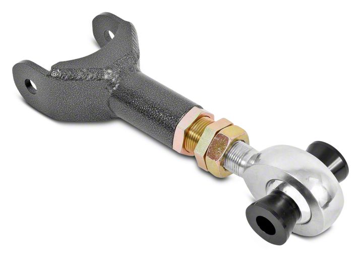
How to Install BMR Adjustable Rear Upper Control Arm - Rod End - Hammertone on your Mustang
Tools Required
- 3/8”, ½” drive ratchet or impact wrench
- Sockets – 18mm, 21mm deep, 24mm, 25mm, 27mm
- Hydraulic jack and stands or service lift
- Pry-bar
Shop Parts in this Guide
Installation:
1. Remove the lower rear seat cushion to gain access to the upper control arm mounting bolt. Located directly above the drivers and passengers side footwells there is a push release that detaches the seat cushion. Once each release is popped, the lower seat cushion can be removed.
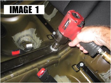
2. Using a 24mm socket, remove the large bolt on the driveshaft tunnel. (IMAGE 1)
3. Lift the vehicle until there is sufficient work space under the car. Support with jack stands.
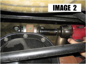
4. Using a 21mm deep socket, remove the upper control arm bolt at the axle. (IMAGE 2)
5. Knock the bolt out, separating the control arm from the axle. NOTE: it may be necessary to support the front of the axle to remove tension from the control arm bolt.
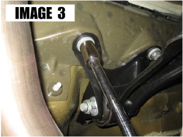
6. Using an 18mm socket and long extension, remove the (2) remaining upper control arm mount bolts and remove the upper control arm mount and control arm out as an assembly. (IMAGE 3)
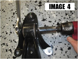
7. Using a 25mm wrench or socket for the bolt head and a 27mm socket for the nut, remove the front control arm bolt as shown in IMAGE 4.
8. If installing an adjustable control arm, adjust the control arm to the approximate length of the OE arm before proceeding.
9. Lube the outside surfaces of the front bushing on the BMR control arm bushing. Mount the BMR upper control arm into the factory mount or the BMR UCM002 mount and re-assemble with the provided new bolt. Tighten to 200 ft/lbs.
10. Re-install the assembly into the car and insert the rear upper mounting bolts. Tighten to 85 ft/lbs.
11. Connect the rear of the BMR control arm to the upper control arm bushing on the rear end. It may require the axle to be rotated to allow the bolt to slide through. Tighten bolt to 129 ft/lbs.
12. Using a grease gun, insert 4-5 pumps of grease into the grease fitting.
13. Lower vehicle and insert the large bolt into the upper mount inside the car. Tighten this bolt to 240 ft/lbs.
14. Re-install lower seat cushion.
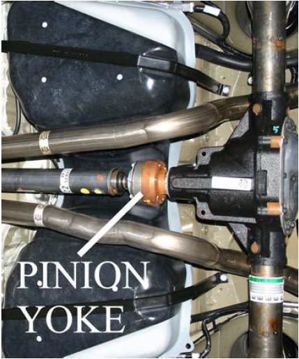
ADJUSTING PINION ANGLE WITH AN ADJUSTABLE UPPER CONTROL ARM
Make sure the rear end is loaded by either setting the car on the ground or letting the car rest on jack stands positioned under the rear axle. In both cases, the car needs to be as level as possible and the suspension loaded.
• Place an angle finder on the rear portion of the two piece driveshaft and record the angle. Now place the angle finder on the pinion yoke and record the angle.
• Subtracting one angle from the other results in your pinion angle (Example: -2 rear end angle subtracted from 0 driveshaft angle = -2 degrees)
• Adjust the control arm to achieve the desired angle.
• As a starting point, most cars respond well to the following initial settings: Automatics: 1-2 degrees negative, Manuals: 2-3 degrees negative
• Once pinion angle has been set, apply Loctite to jam nuts and tighten.