 FREE 1 to 3-Day Delivery on Orders $149+ Details
How to Install a Roush Rear Valance - Unpainted on Your 2005-2009 Mustang GT
Installation Time
3 hours
Tools Required
- Ratchet
- Sockets
- Soft Cloth
- #2 Phillips Head Screw Driver
- Drill
- Drill bits (1/4", 1/8", 5/16")
- Reciprocating Saw (Jig Saw)
- Grease Pencil
- Roll of Masking Tape
Installation
Packaging List for Complete Rear Fascia Valance Kit #R03030060
| Item | Quantity |
|---|---|
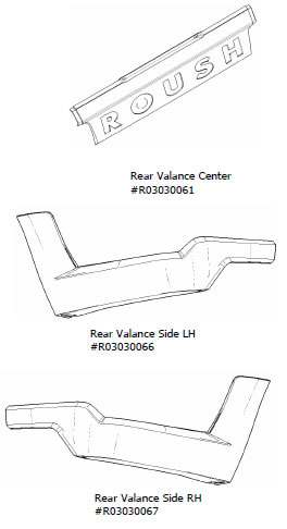
| Rear Valance Center (#R03030061) | 1 |
| Hardware Kit, Valance Center (#R03030068) | 1 |
| Template Lower Holes | 1 |
| Bracket, Valance Center RH | 1 |
| Bracket, Valance Center LH | 1 |
| Bracket, Valance Center | 1 |
| Pin, 6.35x27mm Push | 6 |
| Scrivet, 10.4x25.4mm | 2 |
| Screw, M4.2x1.41x18mm Hex | 4 |
| U-Nut, M4.2x1.41mm | 4 |
| Tape, 12x100mm Adhesive | 2 |
| Tape, 12x275mm Adhesive | 1 |
| Rear Valance Side LH (#R03030066) | 1 |
| Rear Valance Side RH (#R03030067) | 1 |
| Hardware Kit, Valance Side (#R03030082) | 2 |
| Bracket, Valance Side ‘Z’ | 1 |
| Bracket, Valance Side ‘U’ | 1 |
| Pin, 6.35x27mm Push | 4 |
| Screw, M4.2x1.41x19mm | 2 |
| Screw, M4.2x1.41x18mm Hex | 3 |
| U-Nut, M4.2x1.41mm | 3 |
| Tape, 8x195mm ‘L’ Adhesive | 1 |
| Tape, 12x40mm Adhesive | 1 |
| Tape, 12x85mm Adhesive | 1 |
| Tape, 6x420mm Adhesive | 1 |
| Drill Template, Rear Valance Center (#R03030089) | 1 |
| Installation Instructions (#R03030076) | 1 |
Suggested Materials
- Dupont® 2319 Plastic Prep
- Dupont® 2330S or equivalent Adhesion Promoter (for paint)
- 3M 4298 Adhesion Promoter (for double-sided tape)
LIMIT OF LIABILITY STATEMENT
The information contained in this publication was accurate and in effect at the time the publication was approved for printing and is subject to change without notice or liability. Roush Performance Products (RPP) reserves the right to revise the information presented herein or to discontinue the production of parts described at any time.
SAFETY PRECAUTIONS
STOP! CAREFULLY READ THE IMPORTANT SAFETY PRECAUTIONS AND WARNINGS BEFORE PROCEEDING WITH THE INSTALLATION!
Appropriate disassembly, assembly methods and procedures are essential to ensure the personal safety of the individual performing the kit installation. Improper installation due to the failure to correctly follow these instructions could cause personal injury or death. Read each step of the installation manual carefully before starting the installation.
- Always wear safety glasses for eye protection.
- Place the ignition switch in the OFF position.
- Always apply the parking brake when working on the vehicle.
- Block the front and rear tire surfaces to prevent unexpected vehicle movement.
- Operate the engine only in well-ventilated areas to avoid exposure to carbon monoxide.
- Keep yourself and your clothing away from moving parts when the engine is running.
- Do not wear loose clothing or jewelry that can be caught in rotating or moving parts.
- Allow the engine, cooling system, brakes and exhaust to cool before working on a vehicle.
- Do not smoke or use flammable items near or around the fuel system.
- Use chemicals and cleaners only in well-ventilated areas.
- Batteries can produce explosive hydrogen gas which can cause personal injury. Do not allow flames, sparks or flammable sources to come near the battery.
- Keep hands and any other objects away from the radiator fan blades.
1. Paint Preparation
a. Wipe each part with plastic prep (Dupont® 2319 or equivalent)
b. Wipe entire part with tack cloth
c. Apply adhesion promoter (Dupont® 2330S or equivalent) prior to color and clear coat applications. This part is made of TPO (Thermoplastic Polyolefin) and requires a promoter for paint adhesion.
2. Pre-Installation
a. Wear eye protection
b. Clean Rear fascia and quarter panel thoroughly before using drill template.
c. Lift vehicle up for removal of rear wheels
d. Secure vehicle on jack stands
e. Remove the rear wheels
3. Remove Fascia Attachments
a. Remove pushpins underneath the fascia, 3 total (Refer to Figure A).
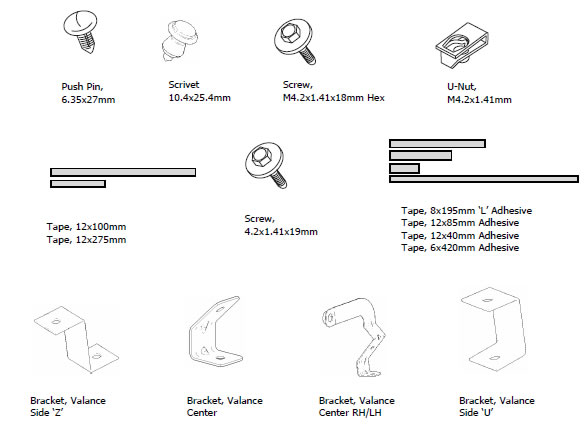
Figure A
b. Remove the trim from the inside of the trunk, by removing 4 pushpins and 2 plastic fasteners (Refer to Figures B & C).
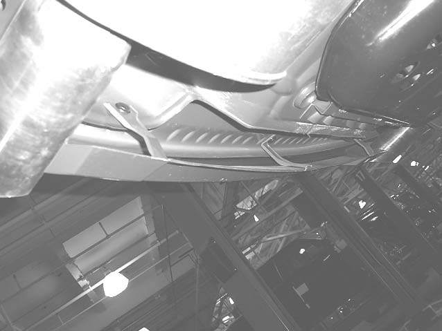
Figure B & C
c. With the trunk trim removed, loosen the nuts that secure the rear fascia to the vehicle until they are near the ends of the studs, 4 total (Refer to Figure D)
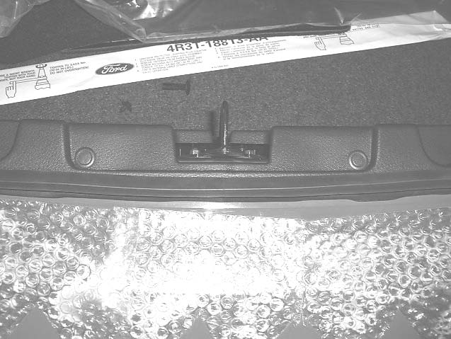
Figure D
d. Remove screws in the rear wheel well that hold the fascia to the body, 2 each side (Refer to Figure E). Keep the screws; they will need to be replaced when the valance is reinstalled.
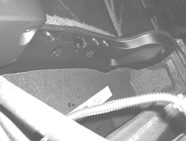
Figure E
4. Drill Fastener Holes in Rear Fascia
1. Rear Valance Center, Lower Holes
a. Tape Drill Template #R03030089 to rear fascia (Refer to Figure L).
b. Pre drill holes (3) with 1/8” drill bit, and then drill holes (3) using 5/16” drill bit.
c. Remove drill template from rear fascia.
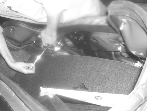
Figure L
5. Prepare Rear Valance
1. Rear Valance Center (Refer to Figure F for the following steps):
a. Install supplied u-nuts to center valance, 4 total.
b. Apply adhesion promoter to the areas where double-sided tape will be used.
c. Install supplied tape strips to center valance.
(12x100) End locations between u-nuts, 2 places
(12x275) Center location between u-nuts
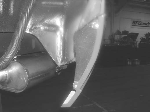
Figure F
2. Rear Valance Side LH/RH (Refer to Figure G, next page, for the following steps):
a. Install supplied u-nuts to side valance, 3 per side.
b. Apply adhesion promoter to the areas were double-sided tape will be used.
c. Install supplied tape strips to side valance.
Tape (8x195mm) ‘L’ surface, 1 per side.
Tape (12x40mm), 1 per side.
Tape (12x85mm), 1 per side.
Tape (6x420mm) along valance top edge, 1 per side.
d. Repeat procedure for other side valance.
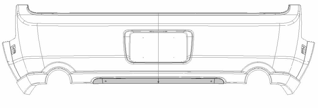
Figure G
3. Mark Faster Hole Center Line on Valance Components
a. Using a grease pencil mark the center of the fastener locations on the top outside edge of the valance components: Rear Valance Side LH/RH and Center (Refer to Figure H)
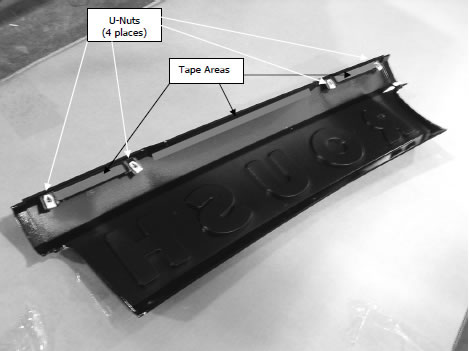
Figure H
6. Modify Rear Fascia
1. Install Center Valance to rear fascia. The top of the valence should fit flush with the body lines of the rear fascia/license plate indent. (Do not remove red tape covering at this time).
a. Use masking tape to fixture center valance to the vehicle (Refer to Figure I)
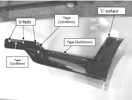
Figure I
2. Install side valances (Do not remove red tape covering at this time).
a. Hold Side Valences onto vehicle
b. Check fit of parts: verify consistent gaps to body and center valence.
c. Align holes of Side Valances to the 2 screws in the wheel well (2 per side).
d. Use masking tape to hold the side valences in place. Trace the outline of the Center, LH, and RH Side Valence onto the rear fascia with a grease pencil.
e. Transfer the fastener center line marks from the Center, LH, and RH Side Valence onto the rear fascia with a grease pencil. (Refer to Figure J).
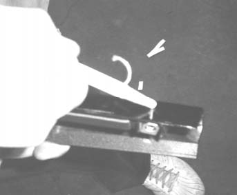
Figure J & K
f. Measure 22 mm down from trace outline where fastener center line marks are identified (Refer to Figure K). This is the drill location for the valence fastener holes.
g. Pre drill mounting holes with 1/8” drill bit, and then drill holes using 5/16” drill bit.
3. Rear Valance Cutout
a. Trace cutout lines for exhaust tips from RH/LH Rear Valance components (Refer to Figure M).
b. Remove center and side valences from rear fascia of vehicle.
c. Cut above marked lines at the exhaust openings.

Figure M
7. Loosen Rear Fascia
a. With the fascia attachments removed/loosened the fascia can be loosened from the car.
b. Grabbing the fascia at the wheel well, carefully pull the fascia clear of the car. There will be a pop as fasteners release (Refer to Figure N).
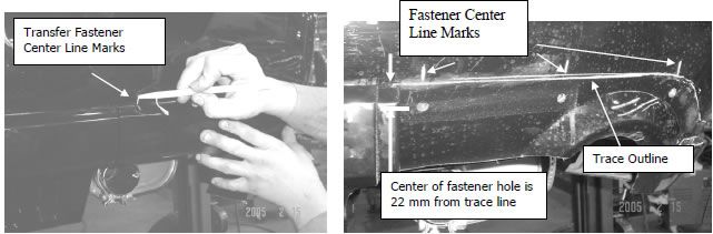
Figure N
c. Holding the loosened fascia at the wheel well push the fascia rearward to further loosen the fascia from the car. There will be a pop as fasteners release (Refer to Figure O).
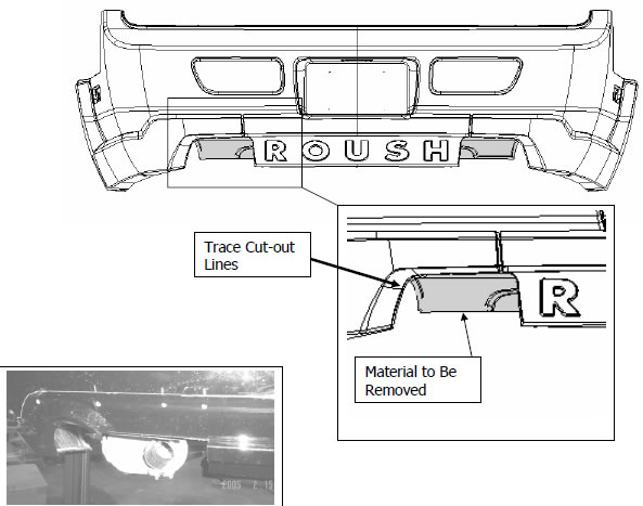
Figure O
d. The fascia should be loose from the car, attached only by the 4 nuts loosened to the ends of the studs.
8. Center Valance Installation
a. Apply adhesion promoter to the rear fascia in a 1/2in strip just below the previously marked grease pencil lines. This is the area where the Center Valance double-sided tape will interface the rear fascia (Refer to Figures P a. and b.).
b. Install center valance to rear fascia by removing tape backing just enough to make a tab to pull once part is correctly situated on vehicle (Refer Figure Q).
c. Once the part is aligned to previously marked grease pencil lines, pull the tape backing off using the tabs and press firmly to ensure good adhesion (Refer Figure R).
d. Reach into the loosened fascia and install M4.2 x 18-mm screws into center valance (4 total). Do not over tighten screws or warping of the fascia will occur.
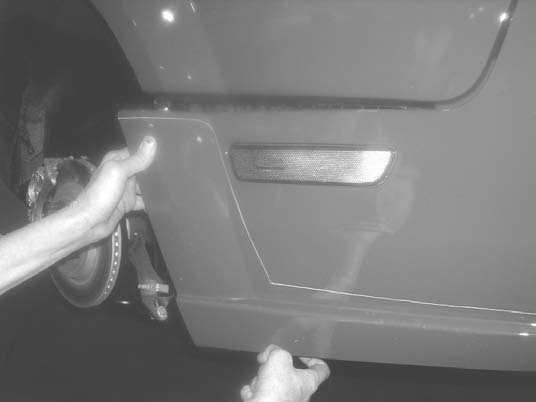
Figure P
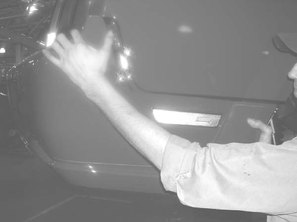
Figure Q
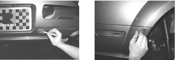
Figure R
9. Side Valance Installation
a. Install side valances to rear fascia by removing tape backing just enough to make pull-tabs. Align part to previously marked lines.
b. Once the part is aligned to previously marked grease pencil lines, pull the tape backing off using the tabs and press firmly to ensure good adhesion (Refer to Figure S).
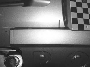
Figure S
c. Reaching into the loosened fascia, install M4.2 x 18 mm screws into side valances (3 each side). Do not over tighten screws or warping of the fascia will occur.
10. Replace Fascia
a. Replace the rear fascia. Reverse the steps of the Loosen Rear Fascia section.
b. With fascia seated properly to rear of vehicle, reengage fascia sides into body retaining clips.
c. When the fascia is in place, replace the screws in the wheel wells (2 each side) and tighten the nuts from inside the trunk.
d. Replace pushpin into the center fascia support found underneath the fascia. (Note- this is the only support remaining, the other two were removed for exhaust cutouts)
11. Valance Brackets installation
1. Install “L” brackets to the Center Valance.
a. Fasten using pushpins, 2 each bracket (Refer to Figure T).
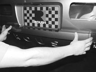
Figure T
b. Using the existing hole in the Center Valance as a guide, drill a hole into the fascia using a ¼” drill bit. Install the middle bracket using pushpins (2) through the “guide” hole and the “drilled” hole (Refer to Figure U).
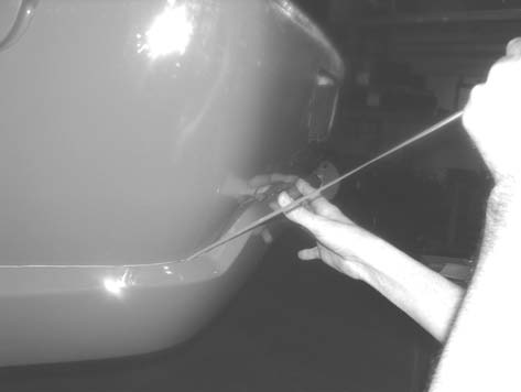
Figure U
2. Installing “U” Brackets to Side Valances
a. Using the existing holes in the side valance(s) as a guide, drill a hole into the fascia using a ¼” drill bit. Install the “U” bracket using pushpins (2 each side) through the “guide” hole and the “drilled” hole (Refer to Figure V).
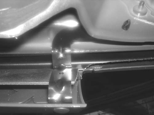
Figure V
b. Using the existing holes in the side valance(s) as a guide, drill a hole into the fascia using a ¼” drill bit. Install the “Z” bracket using pushpins (2 each side) through the “guide” hole and the “drilled” hole (Refer to Figure W).
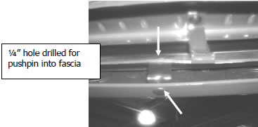
Figure W
Congratulations!!! You have completed the installation of the ROUSH Performance Products, Ford Mustang Rear Fascia Valance Kit. It is recommended that you save all parts removed from your vehicle during the installation of this kit.
Related Guides
-
Installation
-
Installation
-
Installation
