 FREE 1 to 3-Day Delivery on Orders $119+ Details
Best Sellers


Steeda X-2 Ball Joint Kit - Installation Instructions
Installation Time
1 days
Tools Required
- Ball Joint Press Kit (available to rent at most automotive hardware stores)
- Ratchet 2 needed 3/8" or 1/2" drive to fit the following sockets
- Sockets 15mm, 15mm deep, 13/16" (need two), 18mm deep, 1/4" (6 or 12 point)
- Breaker bar or pipe to slide over ratchet handle
- 15/16" wrench for the ball joint nut, second large wrench to link with 15/16" wrench
- Adjustable crescent wrench
- Hammer
- Pliers
- Sledgehammer
- Pry bar
- Floor jack
- 2 Jack Stands
- 4 bricks or 2"x4" blocks of wood to chock rear wheels
- Zip ties (12 size)
- PB Blaster or some other penetrating fluid
- Blue thread locker
- Grease gun
- Suspension grease
Installation
1. SAFETY PRECAUTIONS: Engage the parking brake and put a 2"x4" block of wood (or brick) in front and behind of each rear wheel to make sure the car cannot move while you are working. Also, walk around the car to make sure you have a clear working space around and under the car.
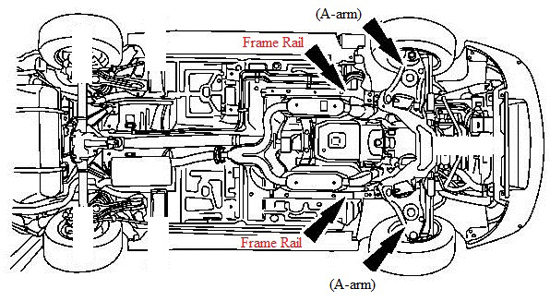
2. Begin by breaking loose each of the 5 lug nuts on each front wheel, using your mustang’s lug nut wrench. Once they begin to turn, stop and do not continue to loosen them. Next place your floor jack under the front A-arm (pictured below) and raise your car enough to slide the first jack stand under the frame rail (also pictured below). Next, jack the other A-arm up and slide the second jack stand in place under the frame rail.
3. Next, remove the wheel lug nuts from both front wheels and take the wheels off. For added safety I always slide the wheels under the frame rails, behind the jack stands. I recommend you do the same.
4. Begin the installation on the driver’s side of the car, by removing the brake caliper from the spindle. The caliper is attached by two 15mm bolts. Once these are removed, use a zip tie to support the brake caliper so that it does not strain the brake line. Also, be careful not to drop or twist the caliper so you will not damage the brake line. Next, use the pliers to remove and discard the circular clips on the wheel studs that hold the rotor down. These do not need to be replaced and may have already been removed depending on what work has already been done on the car. Now you can slide the rotor off the hub assembly and set it aside.
5. Next, straighten and remove the cotter pin that goes through the castle nut that attaches the tie-rod. Then use an 18mm deep socket and remove the castle nut itself. Now the tie rod can fall out of the spindle, however, it may require some persuasion. If it doesn’t come out on its own, first, spray it with penetrating fluid. Let it sit for a few Mins and then hit the top of the bolt with a hammer to force it out.
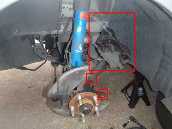
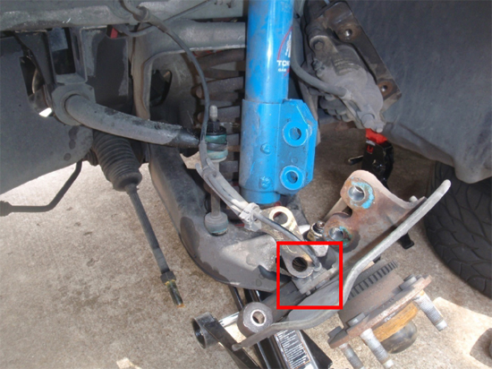
6. After this, you are ready to disconnect the strut. Place the jack under the A-arm again and raise the jack only until it puts pressure on the A-arm. Then loosen the bolts that attach the strut to the spindle. First, remove the nut that holds the ABS bracket in place using a 15/16” wrench. Then, using two 13/16” ratchet/socket combinations or one socket and one box end wrench, loosen the two bolts and remove them. (Note: My tie-rod ends are removed in this picture. That is because I was replacing them. DO NOT remove them for the ball joint installation. Once they are dropped out of the spindle they will be out of your way.)
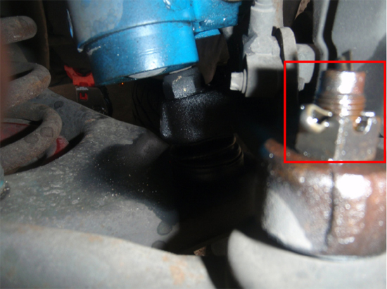
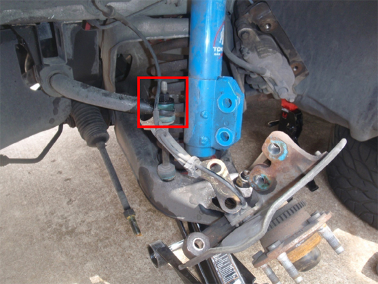
7. Continue with the driver’s side, and disconnect the sway bar end link nut. This nut is also 15mm in size but you will need a deep socket. If you just remove the top nut and top bushing, that is enough.
8. Finally, if your car has ABS, you need to remove the ABS sensor from the spindle using a ¼” 6-point socket. I used a 12-point, which also works fine. Once removed, lay the sensor on top of the caliper where it is out of the way.
9. Now that all the front steering and suspension components have been detached, the next thing you want to do is SLOWLY lower the jack still holding the A-arm, until it no longer supports the A-arm. At this point, you should be able to pry your coilspring out of its place using a pry bar, and set it aside. Jack the A-arm back up without the spring in place so that you have a good angle to work on the ball joints. Also make sure the jack is not under the ball joint or you will not be able to get the press in place to use it.
10. The next task is to remove the ball joint nut using a 15/16” wrench. I recommend a second wrench to link with the 15/16” or a breaker bar that slides over the wrench handle, so that you can generate more torque. These ball joint nuts are really on there.
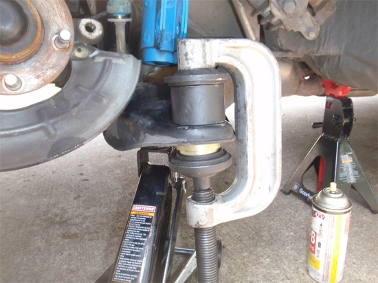
11. Once the nut is removed, the ball joint needs to be pressed out of the A-arm. Using your ball joint press, orient the C-shaped part of the tool such that screwing in, makes the shaft go towards the ground. Put the smallest spacer that fits over the outside of the ball joint underneath it, between the end cap that fits the spacer and the bottom of the C-shape. Put the other end cap between the top of the ball joint shaft and the drive end of the C-shape. Begin screwing it in until everything is tight. Make sure everything is lined up and continue to screw in the press. Since the ball joint is concealed under the spacer (this is what gives it room to slide out) you will not be able to see it moving. BUT, you should feel it get easier to press as you keep going. Eventually, it will slide all the way free and will only be held in place by the spindle. Here is a crude photo of how to orient the press for ball joint REMOVAL:
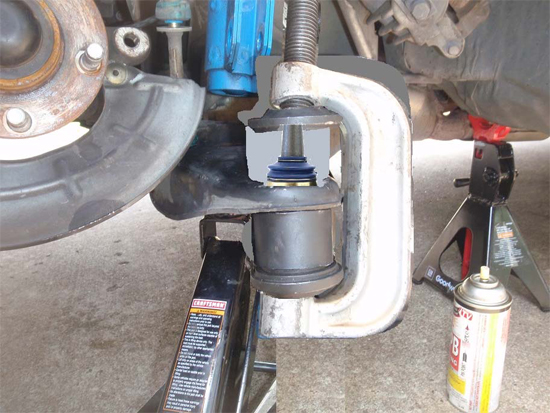
12. I apologize for the poor quality – I forgot to take a picture of the removal setup. This at least gives you a picture of how to setup the tool to press out the ball joint. The spindle is not in this photo but will be between the A-arm and the top of the ball joint.
13. The next step in the installation is by far the most difficult. The tapered end of the ball joint that the spindle sits on, will most likely be stuck to the spindle, even though there are no nuts holding it in place. If you have an air hammer and pickle fork, power it up and place the pickle fork on the ball joint shaft, under the spindle and try to jar it loose. Eventually, the hammering will free up the ball joint and it will drop out of the A-arm. The spindle will most likely fall to the ground as well so watch your feet!
14. Now you need to adjust the bump steer kit. Drive the front of the car up on your ramps at this time. Looking at the suspension from the front of the car, you want to see what angle the tie-rods are at, relative to the A-arms. You want them to be parallel with the A-arms to eliminate bump steer. Here are three figures which explain the possibilities. In these figures, the blue, thicker, bottom line represents the angle of the A-arm, which remains the same in each figure. It also remains fixed on your car as it sits on the ramps.
15. If you do not have an air hammer, you can try to knock it out using a sledgehammer. However, the problem I found with this method is that you really do not have enough room to get the swing you will need to knock it free.
16. So, what I did was to buy a disposable propane torch, and heat the ball joint shaft through the rubber boot, underneath the spindle. It worked really well and dropped right out after 20 seconds of heating. I actually recommend this method, as I felt like trying to just knock it out was a waste of time and effort.
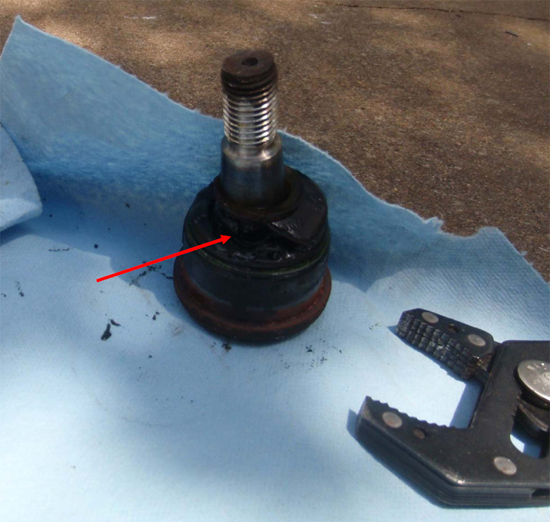
17. To heat it up, you first need to press the ball joint back into the A-arm just enough so that it stays in place. Refer to step 13 below to see how to press a ball joint back in the A-arm. This will give you room to heat the ball joint under the spindle while also giving you something solid to hit once you are done heating. Once it is secured, fire up the torch and begin melting away a section of the rubber boot of the ball joint. Once it is melted continue to heat the metal shaft of the balljoint where the rubber boot used to conceal it. Do not put direct heat on the spindle itself or the A-arm, as these components will be reused and you do not want to risk weakening the metal. After about 20 seconds of heating, turn off your torch and use normal hammer to knock the ball joint free from the spindle and A-arm, by hitting it on top with a hammer. It should pop right through to the ground. The spindle will fall to the ground also, so watch your hands and feet! If it does not come free, heat it for another 20 seconds and then hit it again. Here is a picture of my stock ball joint removed. You can see where I melted the rubber boot and heated the shaft of the ball joint. (Note: If you do choose to use this method, be careful with the torch. It produces a blue flame that is hard to see and VERY hot.)
18. Now that you have all the old ball joints removed, you can press the new ones in. Take the new Steeda X2 ball joint (WITHOUT the grease fitting installed) and gather your press tool and its attachments. This time, orient the C-shape so that it screws in away from the ground (opposite of before). Put the spacer and end cap that fits the spacer, on the top of the A-arm. The new ball joint will sit on the other end cap, underneath the Aarm. Here is an image that illustrates the setup for pressing the new ball joints in.
19. Once you have the tool setup correctly, screw in the press until the lip on the bottom of the ball joint is flush against the A-arm and the pressing is difficult to continue. Loosen the press and the ball joint will be in place.
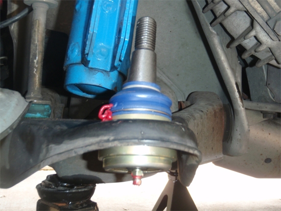
20. Next, screw the grease fitting into the bottom of the ball joint until it is tight. DO NOT over-tighten this fitting. Pump the ball joint full of grease until it seeps out the bleed hole on the side of the boot. I used Motorcraft general-purpose suspension grease (red) and a standard grease gun.
21. Next, slide the spindle over the ball joint shaft and hand tighten the new ball joint nut that was included with the new ball joints. I would recommend using blue thread locker on the ball joint threads but that is just my personal preference. Use the 15/16” wrench to tighten the ball joint nut until the ball joint shaft begins to spin, preventing further tightening. At this point, an impact wrench would be useful to further secure the nut but if you do not have one, you can get a good sized friend or family member to stand on the spindle (both feet) while you continue to tighten it. This will allow you to tighten the nut further than it previously allowed because the increased weight will keep the shaft from spinning. Combined with thread locker, this will make the ball joint nut secure and stay that way.
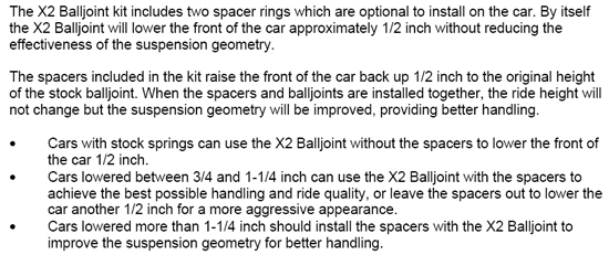
22. Next you need to drop out the jack that was holding the A-arm up and grab your coil spring. You also need to make a decision about the spring spacers if you have not already. The installation instruction Steeda provides are useful, however, in explaining the purpose of the included spring spacers. I recommend following these guidelines so that your mustang’s handling will be improved as much as possible. This is what they say:
23. So, depending on your application, begin reinstalling the front suspension and steering components by putting the coil spring back in the A-arm with or without the Steeda spring spacers between the top of the spring and the top spring perch.
24. Once the spring is in position, place the jack under the A-arm one more time and jack the A-arm up, making sure that the spring remains in position on the spring perches. Also, make sure that you force the sway bar end-link through the eye of the sway bar while jacking it up or you will have to lower it back down and try again.
25. Once the spring is in position, reinstall the suspension and steering components beginning with the last thing that was removed and continue backwards. The reinstall order should be: ABS sensor, sway bar end link bushing and nut, strut to spindle and ABS bracket, tie-rod end, and rotor and brake caliper. Refer to steps 4-9 for images and tools required. Be sure to re-bend the cotter pin once you slide it through the castle nut of the tie-rod end.
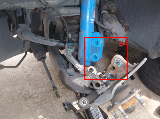
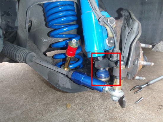
26. Here is an image showing the new ball joints installed and the rest of the front suspension put together. Note: the rotor and caliper are not installed in this image but should be on your car.
27. Congratulations, you’re halfway done! Now repeat steps 4-26 on the passenger side of the car. The passenger side is the exact same process because all the components are identical.
28. Finally, put the wheels back on the car, tighten the lug nuts, lower the car, and torque the lug nuts down. Take it for a spin and enjoy!
Installation instructions provided by AmericanMuscle customer Jon David Johnson 10.5.09
Best Sellers
Related Guides
-
Installation
-
Installation
-
Installation
