FREE 1 to 3-Day Delivery on Orders $119+ Details
Best Sellers


How to install Ford Racing Gears on your 2005-2010 GT Mustang
Shop Parts in this Guide
- Ford Performance Ring and Pinion Gear Kit; 3.55 Gear Ratio (05-09 Mustang GT)
- Ford Performance Ring and Pinion Gear Kit; 3.55 Gear Ratio (10-14 Mustang GT)
- Ford Performance Ring and Pinion Gear Kit; 3.55 Gear Ratio (11-14 Mustang V6)
- Ford Performance Ring and Pinion Gear Kit; 3.55 Gear Ratio (86-93 Mustang GT)
- Ford Performance Ring and Pinion Gear Kit; 3.55 Gear Ratio (94-98 Mustang GT)
- Ford Performance Ring and Pinion Gear Kit; 3.55 Gear Ratio (99-04 Mustang GT)
- Ford Performance Ring and Pinion Gear Kit; 3.73 Gear Ratio (05-09 Mustang GT)
- Ford Performance Ring and Pinion Gear Kit; 3.73 Gear Ratio (10-14 Mustang GT)
- Ford Performance Ring and Pinion Gear Kit; 3.73 Gear Ratio (11-14 Mustang V6)
- Ford Performance Ring and Pinion Gear Kit; 3.73 Gear Ratio (86-93 Mustang GT)
- Ford Performance Ring and Pinion Gear Kit; 3.73 Gear Ratio (94-98 Mustang GT)
- Ford Performance Ring and Pinion Gear Kit; 3.73 Gear Ratio (99-04 Mustang GT)
Installation
Axle Shaft Removal (1994-2012 Mustang typical)
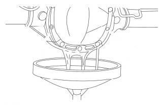
STEP 1: Remove the 10 differential housing cover bolts and drain the lubricant from the axle housing.
STEP 2: Remove the differential housing cover.
STEP 3: Mark driveshaft position and remove driveshaft
STEP 4: Remove the rear brakes
NOTE: Care must be used when servicing rear brake components without disconnecting the parking brake cable from the brake caliper lever. Carefully position the caliper aside using a suitable support or damage to the parking brake cable end fittings may occur.
NOTE: Do not use caliper sight hole to retract pistons as this may damage the pistons and boots.
NOTE: Do not allow the caliper to hang from the brake hose or damage to the hose may occur.
NOTE: Damage to the rear wheel speed sensor may occur if it is not removed before the axle shaft U-washer
STEP 5: Remove the bolt and position the rear wheel speed sensor aside.
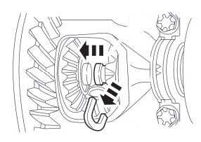
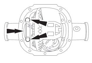
STEP 6: Remove the differential pinion shaft. Traction-Lok® and open differentials.
a. Remove and discard the differential pinion shaft lock bolt.
b. Remove the differential pinion shaft.
NOTE: Do not damage the rubber O-ring in the axle shaft grooves.
STEP 7: Remove the axle shaft U-washer.
a. Push in on the axle shaft.
b. Remove the U-washer.
NOTE: Do not damage the axle shaft oil seal.
STEP 8: Remove the axle shaft.
Remove Differential
CAUTION: BEARING CAPS MUST BE REINSTALLED IN THEIR ORIGINAL POSITIONS.
STEP 1: Mark the differential bearing caps to help position the caps properly during reassembly.
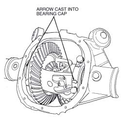
STEP 2: Loosen differential bearing cap bolts and bearing caps. Note direction of arrows on bearing caps. When assembled, arrows must be pointing in same direction as before removal.
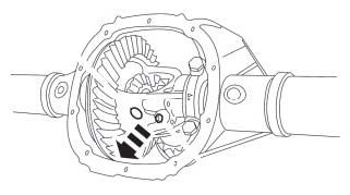
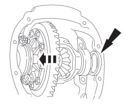
STEP 3: Pry out differential case, differential bearing cups and differential bearing shims until they are loose in the bearing caps. Remove bearing caps and remove differential case from rear axle housing. Note location of differential shims.
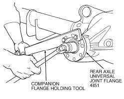
Remove Companion Flange
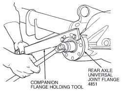
STEP 1: While holding rear axle universal joint flange with Companion Flange Holding Tool, remove pinion nut.
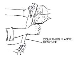
STEP 2: Remove rear axle universal joint flange with Companion Flange Remover.
STEP 3: With a soft-faced hammer, drive pinion out of differential pinion bearing and remove through rear of rear axle housing.
STEP 4: Remove rear axle drive pinion seal as described.
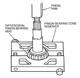
STEP 5: To remove and install the differential pinion bearing, use Pinion Bearing Cone Remover and PinionBearing Cone Replacer.
NOTE: Measure drive pinion bearing adjustment shim, which is found under rear axle pinion bearing, with a micrometer and record thickness. Use this as a reference to compare with shim gauge reading prior to installing rear axle pinion bearing.
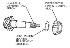
STEP 6: Remove drive pinion bearing adjustment shim from drive pinion.
Pinion Bearing Cup Removal
NOTE: To make sure of proper seating, clean bores before installing new cups. Inspect rear axle pinion bearing cups. If damaged, remove from rear axle housing by tapping alternately (with a brass drift of suitable length) on each side of rear axle pinion bearing cups to prevent rear axle pinion bearing cups from cocking in rear axle housing bore.
WARNING: Some 8.8 axle assemblies such as the 2007-2010 SVT Mustang have a spacer between the rear pinion bearing cup and the axle housing. Save spacer for reuse if installing an identical replacement bearing and cup.
Differential Case Runout Check:
To determine excessive runout, proceed as follows:
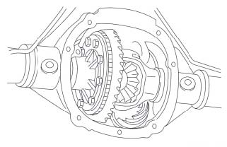
STEP 1: With pinion removed, place differential case (ring gear removed) with differential bearings and differential bearing cups in rear axle housing.
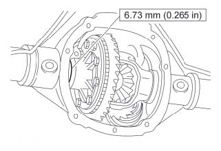
STEP 2: Install a 6.75 mm (0.265-inch) differential bearing shim on LH side of subassembly.
STEP 3: Install LH bearing cap finger-tight.
STEP 4: Install progressively larger differential bearing shims on RH side until largest differential bearing shim selected can be assembled with a slight drag feel.
STEP 5: Install RH side bearing cap. Install bearing cap bolts. Tighten both RH and LH bolts to 102-122 Nm (76-89 lb-ft).
STEP 6: Rotate assembly to make sure of free rotation.
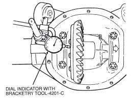
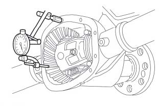
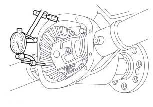
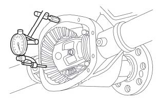
STEP 7: Install Dial Indicator with Bracketry TOOL-4201-C or equivalent. Check and note differential case runout. (shown with ring gear installed)
STEP 8: Note differential runout. Maximum differential case runout .003" If runout is excessive, differential case is damaged and should be replaced.
STEP 9: Remove differential case from rear axle housing.
Axle Assembly:
Pinion Bearing Cup Installation
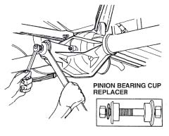
Install new pinion bearing cups with Pinion Bearing Cup Replacer. Make sure pinion bearing cups are properly seated in their bores. If a 0.038 mm (0.0015-inch) feeler gauge can be inserted between pinion bearing cup and the bottom of its bore at any point around the pinion bearing cup, the pinion bearing cup is not properly seated. Whenever pinion bearing cups are replaced, differential pinion bearings should also be replaced.
WARNING: Install spacer behind rear pinion bearing cup if required for your application. Replacement bearing assembly must be same as the bearing assembly that was removed to allow use of spacer.
Pinion Shim Selection Overview
Ford Racing and Ford OEM gears do not use the same pinion depth method of setup as aftermarket gears. Shimming is done to compensate for differences in the machining of the axle housing. If you are removing a Ford OEM gear, the use of the same thickness pinion shim on the new Ford Racing gear, most times will allow you to achieve correct tooth contact pattern with only minor adjustments.
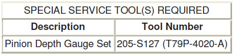
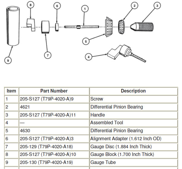
A drive pinion bearing adjustment shim (0.254 mm to 0.965 mm) (0.010 to 0.038 inch) is used between differential pinionbearing and pinion head. The drive pinion bearing adjustment shim compensates for machining variations in rear axle housing, differential ring gear and pinion and differential pinion bearings. The correct drive pinion bearing adjustment shim size will locate pinion for proper tooth contact with ring gear. Selecting correct drive pinion bearing adjustment shim when installing a new differential ring gear and pinion can be done by using Pinion Depth Gauge Set 205-S127 (T79P-4020-A) as described.
NOTE: This tool is for use with Ford Racing/OEM gears only!
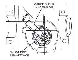
Assemble the appropriate aligning adapter, gauge disc and gauge block to the screw as shown.
NOTE: The gauge block must be off-set to obtain an accurate reading.
STEP 1: Place differential pinion bearing (new, or used if in good condition) over aligning disc and insert into rear axle pinion bearing cup of carrier. Place differential pinion bearing into bearing cap and assemble tool handle into screw and tighten to 2.2 Nm (20 lb-in).
STEP 2: Make sure gauge handle adapter screw, aligning adapter, gauge disc and gauge block assembly are securely mounted between front differential pinion bearing and rear differential pinion bearing. Check tool handle torque prior to gauging to make sure that bearings are properly seated. This can affect final shim selection when improperly assembled. Clean rear axle pinion bearing cups and differential pedestal surfaces thoroughly. Apply only light oil film on bearing assemblies prior to gauging.
STEP 3: The gauge block should then be rotated several half turns to make sure rollers are properly seated in rear axle pinion bearing cups. Rotational torque on the gauge assembly should be 2.2 Nm (20 lb-in) with new bearings. Final position should be approximately 45 degrees across gauge tube to make sure gauge block is in line with gauge tube high point. This area should be used for drive pinion bearing adjustment shim selection. Selection of drive pinion bearing adjustment shim with gauge block not lined up with tube high point will cause improper drive pinion bearing adjustment shim selection and may result in axle noise.
NOTE: Shims must be flat. Do not use dirty, bent, nicked or mutilated drive pinion bearing adjustment shims as a gauge.
STEP 4: Use drive pinion bearing adjustment shims as gauge for shim selection. This will minimize errors in attempting to stack feeler gauge stock together. It will also minimize simple addition errors in calculating correct shim thickness.
NOTE: Use the same differential pinion bearing in this procedure during final assembly of the axle. Feeling slight drag on drive pinion bearing adjustment shim is important for correct selection. Do not attempt to force drive pinion bearing adjustment shim between gauge block and the gauge tube. This will minimize selection of a drive pinion bearing adjustment shim thicker than required which results in a deep tooth contact in final assembly of integral axles.
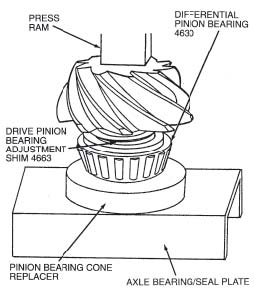
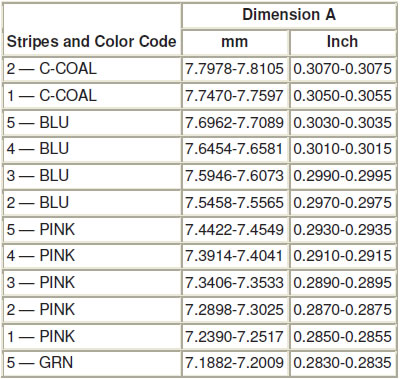
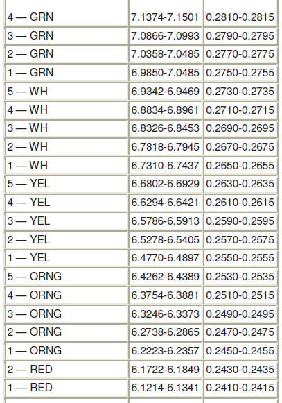
STEP 5: Place selected drive pinion bearing adjustment shims on pinion shaft and press differential pinion bearing until firmly seated on shaft.
STEP 1: Make sure splines on pinion stem are free of burrs. If burrs are evident, remove by using a fine crocus cloth, working in a rotational motion. Wipe pinion clean.
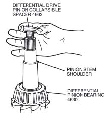
STEP 2: Place new differential drive pinion collapsible spacer on pinion stem against pinion stem shoulder.
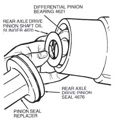
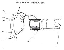
NOTE: Clean flange yoke seal surface before installing rear axle drive pinion seal in rear axle housing bore. Coat lips of rear axle drive pinion seal with Premium-Life Grease XG-1-C or equivalent meeting Ford specification ESA-M1C75-B.
STEP 3: Install differential pinion bearing and rear axle drive pinion shaft oil slinger in housing bore. Install rear axle drive pinion shaft oil slinger on Pinion Seal Replacer.
CAUTION: Installation without proper tool may result in early flange yoke seal failure. If rear axle drive pinion seal becomes cocked during installation, remove it and install new one.
STEP 4: Install rear axle drive pinion seal in rear axle housing.
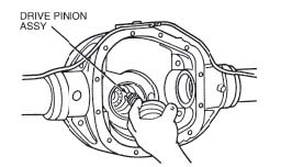
Drive Pinion Assembly Installation
STEP 1: From rear of rear axle housing, install drive pinion assembly (drive pinion, drive pinion bearing adjustment shims, differential pinion bearing and differential drive pinion collapsible spacer) into rear axle housing pinion shaft bore.
Universal Joint Flange, Rear Axle Installation
STEP 1: Apply a small amount of rear axle lubricant to rear axle universal joint flange splines.
CAUTION: The rear axle universal joint flange must never be hammered on or installed with power tools.
STEP 2: With drive pinion in place in rear axle housing , install rear axle universal joint flange using Companion Flange Replacer or equivalent.
STEP 3: Install a new pinion nut on pinion shaft (apply a small amount of lubricant on the washer side of nut).
STEP 4: Hold rear axle universal joint flange with Companion Flange Holding Tool while tightening nut.
STEP 5: Tighten pinion nut. Rotate pinion occasionally to ensure proper bearing seating. Take frequent pinion bearing torque preload readings until proper preload reading is obtained.
STEP 6: Minimum torque required to tighten pinion flange nut to obtain pinion bearing preload, 140 lb-ft.
CAUTION: Never back off pinion nut to reduce preload. If reduced preload is required, a new differential drive pinion collapsible spacer and pinion nut must be installed. Pinion bearing preload with used bearings to 0.9-1.6 Nm (8-14 lb-in), and new bearings to 1.8-3.2 Nm (16-28 lb-in.)
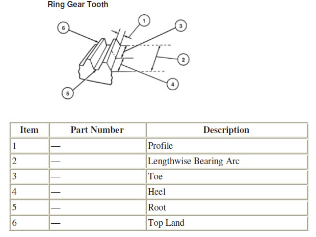
Ring Gear Installation
STEP 1: Inspect mounting face of ring gear for nicks, burrs or other imperfections. Deburr with a stone as necessary.
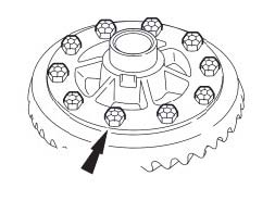
STEP 2: Apply a one-eighth inch bead of maximum strength retaining compound (Loctite® 638) on the rear face of the ring gear in the pattern shown.
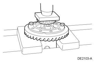
STEP 3: Using 2 ring gear bolts as a guide, press the ring gear on the differential assembly.
STEP 4: Install the 10 new differential ring gear bolts.
a. Tighten to 97-102 lb-ft.
Installation
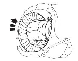
STEP 1: Position the differential assembly in the axle housing.
STEP 2: Install the originally removed differential bearing shim on the LH side.
NOTE: Apply pressure toward the LH side to make sure the LH differential bearing cup is seated. Install the LH differential bearing cap and loosely install the 2 differential bearing cap bolts.
STEP 3: Install the original differential bearing shim on the RH side.
STEP 4: Using the Differential Shim Installer, fully seat the differential bearing shims.
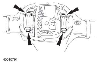
STEP 5: Install the RH side differential bearing cap and tighten the 4 differential bearing cap bolts.
a. Tighten to 90-100 lb-ft.
STEP 6: Rotate the differential assembly to make sure it rotates freely

Adjust the Ring Gear Backlash
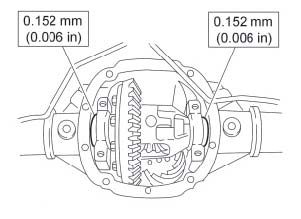
STEP 1: Install the Dial Indicator Gauge with Holding Fixture and measure the ring gear backlash. (.008"-.012")
STEP 2: Backlash should be checked in 4 locations. (.004" maximum variation)
a. If a zero backlash condition occurs or the backlash is not within specification, proceed to Step 3
b. If the backlash is within specification, proceed to Step 14.
STEP 3: Remove the 4 differential bearing cap bolts and 2 caps.
STEP 4: If a zero backlash condition had occurred, add 0.50 mm (0.020 in) to the RH side shim and subtract 0.50 mm (0.020 in) from the LH side shim to allow a backlash indication. Install the 2 bearing caps and 4 bolts.
a. Tighten to 90-100 lb-ft.
b. Go back to Step 2
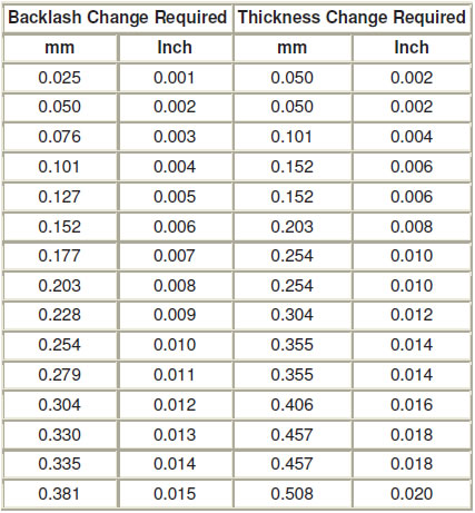
STEP 5: To correct for high or low backlash, increase the thickness of one differential bearing shim and decrease the thickness of the other differential bearing shim by the same amount. Refer to the following tables when adjusting the backlash.

STEP 6: Install the 2 differential bearing caps and 4 bolts.
a. Tighten to 99-100 lb-ft.
STEP 7: Using the Dial Indicator Gauge with Holding Fixture, recheck the ring gear backlash.
a. If backlash is now within specification, proceed to Step 8.
b. If backlash is not within specification, go back to Step 4.
STEP 10: Using the Differential Shim Installer, fully seat the differential bearing shims. Make sure the assembly rotates freely.
STEP 11: Install the 2 differential bearing caps and 4 bolts.
a. Tighten to 90-100 lb-ft.
STEP 12: Using the Dial Indicator Gauge with Holding Fixture, do a final check of the ring gear backlash.
STEP 13: Apply marking compound and rotate the differential assembly 5 complete revolutions.
STEP 14: VERIFY AN ACCEPTABLE TOOTH CONTACT PATTERN!
NOTE: Tooth contact pattern along with proper pinion preload and backlash, determines if a gear set is correctly installed. Do not drive vehicle if pattern is not correct.
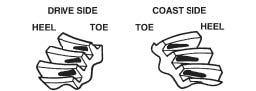
Contact Pattern Location
Desirable ring gear tooth patterns must have the following characteristics:
- Drive pattern on the drive side ring gear well centered on the tooth.
- Coast pattern on the coast side ring gear well centered on the tooth.
- Clearance between the pattern and the top of the tooth.
- No hard lines where the pressure is high.
Tooth Contact Patterns Check of Gearset
STEP 1: Set up ring gear to create a pattern as follows:
a. The final pinion position will be verified by using the gear contact pattern method described as follows:
WARNING: GEAR TEETH MAY HAVE SHARP EDGES. WHEN HANDLING GEARS, USE CARE TO AVOID PERSONAL INJURY.
NOTE: When making changes, note that two variables are involved. For example, if you have the backlash set correctly to specification and you change the pinion position shim, you may have to readjust the backlash to the correct specification before checking the pattern. Refer to illustrations following step 3.
b. High backlash is corrected by moving the ring gear closer to the pinion. Low backlash is corrected by moving the ring gear away from the pinion. These corrections are made by adding and subtracting shim thickness from one side of the differential case to the other.
c. The toe of the gear tooth is the portion of the tooth surface at the end toward the center. The heel of the gear tooth is the portion of the tooth surface at the outer end. The top land of a gear tooth is the surface of the top of the tooth. Every gear has a characteristic pattern. The illustrations show typical patterns only, and explains how patterns shift as gear location is changed. When making pinion position changes, shims should be changed in the range of 0.05 mm (0.002 inch) to 0.10 mm (0.004 inch) until correct pattern has been obtained.
d. When a change in backlash is required, backlash shims should be changed in the range of 1- 1/2 times the amount of backlash required to bring the gears into specification. For example, if the backlash needed to be changed by 0.10 mm (0.004 inch), the shim pack should be changed by 0.15 mm (0.006 inch) as a starting point. The actual amount of backlash change obtained will vary depending upon the ratio and gear size.
Paint ring gear teeth with a marking compound to both the drive and coast side.
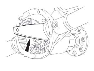
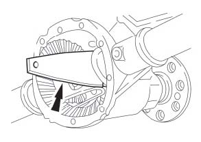
STEP 2: While turning pinion gear rotate ring gear one complete revolution in both directions. Apply load with a large screwdriver or similar tool between the carrier casting and differential case flange.
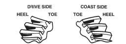
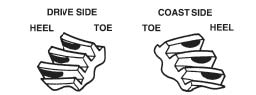
STEP 3: Interpret the pattern left on the ring gear as shown in the following illustrations:
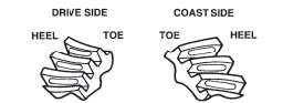
a. Normal or desirable pattern. The drive pattern should be centered on the tooth. The coast pattern should be centered on the tooth, but may be slightly toward the toe. There should be some clearance between the pattern and the top of the tooth.
b. Backlash correct. Thinner pinion position shim required.
c. Backlash correct. Thicker pinion position shim required.
d. Pinion position shim correct. Decrease backlash.
e. Pinion position shim correct. Increase backlash.
STEP 4: Pinion and ring gear movements can be adjusted to obtain satisfactory roll patterns as follows:
a. Decreasing backlash moves the ring gear closer to the pinion.
- Drive pattern (convex side of gear) moves slightly lower and toward toe.
- Coast pattern (concave side of gear) moves lower and toward the toe.
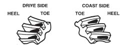
b. Increasing backlash moves the ring gear away from the pinion.
- Drive pattern moves slightly higher and toward the heel.
- Coast pattern moves higher and toward the heel.
c. Thicker pinion position shim with the backlash constant moves the pinion closer to the ring gear.
- Drive pattern moves deeper on the tooth (flank contact) and slightly toward the toe.
- Coast pattern moves deeper on the tooth and toward the heel.
d. Thinner pinion position shim with the backlash constant moves the pinion farther from the ring gear.
- Drive pattern moves toward the top of the tooth (face contact) and toward the heel.
- Coast pattern moves toward the top of the tooth and slightly toward the toe.
Axle Shaft installation
STEP 1: Lubricate the lip of the axle shaft oil seal with grease.
STEP 2: NOTE: Do not damage the axle shaft oil seal when installing the axle shaft. Install the axle shaft
STEP 3: NOTE: Do not damage the rubber O-ring in the U-washer groove.
Install the axle shaft U-washer.
a. Position the U-washer on the button end of the axle shaft.
b. Pull the axle shaft outward.
STEP 4: Install the differential pinion shaft.
- Align the hole in the differential pinion shaft with the differential case lock bolt hole.
- Install a new differential pinion shaft lock bolt.
- Tighten to 35 Nm (26 lb-ft).
STEP 5: Position the rear wheel speed sensor and install the bolt.
- Tighten to 15 Nm (133 lb-in).
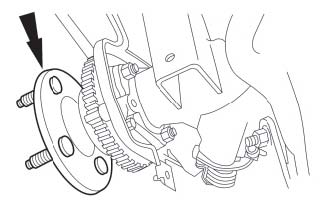
STEP 6: Install the rear brake disc.
Rear Cover Installation
NOTE: Make sure the machined surfaces on both the axle housing and the differential housing cover are clean and free of oil before installing the new silicone sealant. The inside of the axle housing must be covered when cleaning the machined surface to prevent contamination.
STEP 1: Clean the gasket mating surface of the axle housing and the differential housing cover. Verify that the cover is flat.
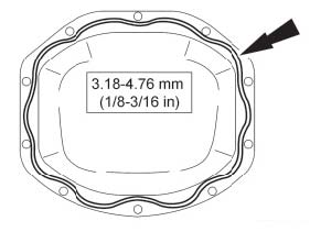
STEP 2: Apply a new continuous bead of sealant to the differential housing cover. For aluminum covers apply a continuous bead in the groove of the cover.
NOTE: The differential housing cover must be installed within 15 minutes of application of the silicone sealant, or new sealant must be applied. If possible, allow one hour before filling the axle housing with axle lubricant to make sure the silicone sealant has cured.
STEP 3: Install the differential housing cover and the differential housing cover bolts.
- Tighten steel cover bolts to 46 Nm (33 lb-ft).
- Tighten aluminum cover bolts to 32 Nm (24 lb-ft).
NOTE: Service refill capacities are determined by filling the axle to the bottom of the fill hole with the axle at ride height. Remove the axle plug, fill the axle with 2.84-2.98L (5-5.25 pt) of axle lubricant and an additional 4.0 oz of friction modifier additive and install the filler plug. Tighten to 30 Nm (22 lb-ft). Motorcraft® SAE 75W-140 Synthetic Rear Axle Lubricant XY-75W140-QL. 2.5L (5.25 pt required) Friction Modifier, M-19546-A12 (case of 12) or Motorcraft XL-3 (4oz.required) Install driveshaft. Align to marks as removed.
Break-In Procedure
STEP 1: Drive the car for at least 30 min. No spirited acceleration.
- Repeat 2 more 30 min. drive cycles
STEP 2: Check gear oil level
WARNING: Aftermarket rear control arms or control arm bushings and panhard bar will more readily transmit gear noise to drivers compartment as compared to production components.