


Installation Time
(approx) 2 Hours
Difficulty Level:
Light to Moderate mechanical skill required.
Installation Guides
No guide available for this part yet.
 FREE 1 to 3-Day Delivery on Orders $149+ Details
$369.99 pair
Save with Open Box
From $221.99
CONFIRM THIS FITS YOUR VEHICLE!
Saved - View your saved items
We're sorry. We couldn't save this product at this time.
or use

Features, Description, Reviews, Q&A, Specs & Installation
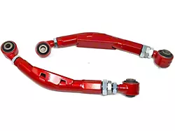
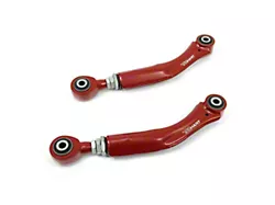
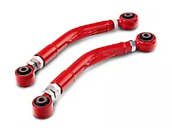
| Control Arm Type | Adjustable |
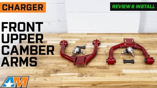
| Control Arm Placement | Front Upper |
Adjustable Style Camber Arms. Improve the driving experience in your Charger with this Adjustable Front Upper Camber Arms with Ball Joints. Designed to boost control and handling of your vehicle, these Steel Alloy Camber Arms allow for Camber adjustment of -/+ 3 degrees. It also comes with corrosion resistant ball-joints for a longer service life.
Installation. For the safety of your hardware during removal and replacement, professional installation is recommended.
Application. The Adjustable Front Upper Camber Arms with Ball Joints fits 2006-2023 RWD Chargers.
CA Residents:  WARNING: Cancer and Reproductive Harm - www.P65Warnings.ca.gov
Installation Info
Installation Time
(approx) 2 Hours
Difficulty Level:
Light to Moderate mechanical skill required.
Installation Guides
No guide available for this part yet.
What's in the Box