 FREE 1 to 3-Day Delivery on Orders $149+ Details
How to Install a Roush Triple Adjustable Coil Over Kit on a 2015-2017 Mustang
Tools Required
- Torque Wrench (Nm)
- Impact Gun
- Air Ratchet
- Trim Tool
- Hammer
- Vise
- 6 mm Hex Bit
- 17 mm Box-End Wrench
- 18 mm Box-End Wrench
- 10 mm Socket
- 13 mm Socket
- 15 mm Socket
- 18 mm Socket
- 21 mm Socket
Rear Suspension Removal
1. Use a vehicle lift, or jack stands, to securely lift the vehicle off the ground. Remove the fi ve (5) lug nuts off the rear driver side wheel using a 21 mm socket.

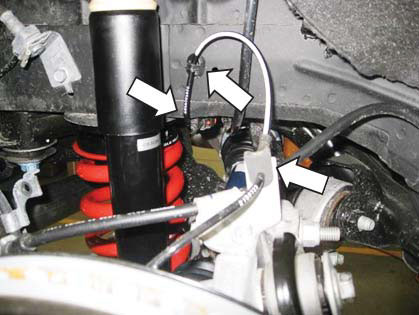
2. Unhook the ABS sensor by hand by pulling it out of the clip. Use a trim tool to release the wire from the back and unplug it from the socket.
3. Place a jack under the lower control arm and lift about 4-6 inches to remove the tension.
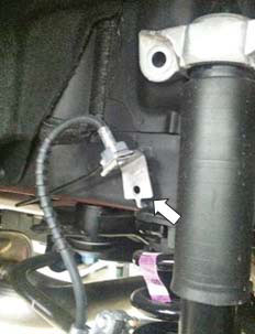
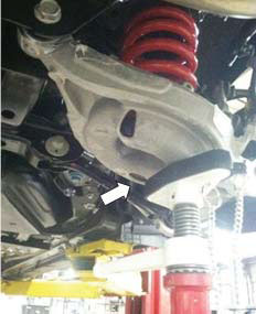
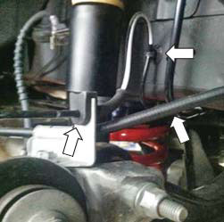
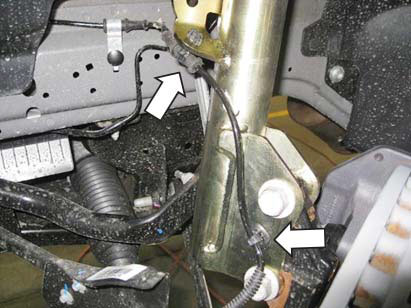
4. Use a 10 mm socket to remove the brake line bracket from the sway bar link.
ROUSH Adjustable Suspension Kit
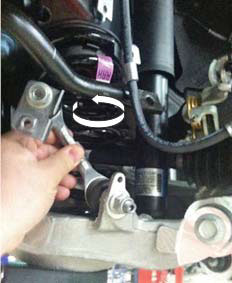
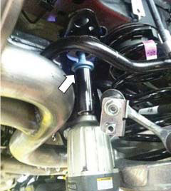
5. Remove the sway bar end link bolt by using an 18 mm box wrench and a 6 mm hex bit.
6. Position the sway bar end link out of the way
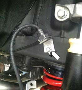
7. Use a 13 mm socket to remove the brake line bracket that is attached to the frame
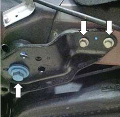
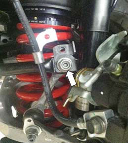
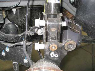
8. Use a 15 mm socket to remove the two (2) lower shock bolts.
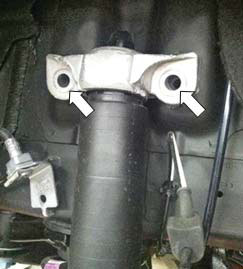
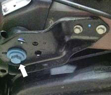
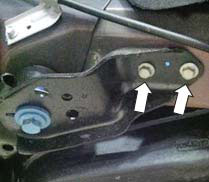
9. Use an 18 mm socket to remove the two (2) upper shock bolts.
10. Pull the shock out of the car and set it aside.
11. Position the jack underneath the sub frame and raise it until the lower control arm swings downward.
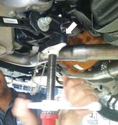
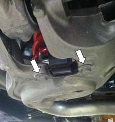
12. On the far right side, use a 21 mm socket to remove the sub-frame bolt. Then use a 13 mm socket to remove two (2) sub-frame bracket bolts.
13. On the left side, use a 21 mm socket to remove the other sub-frame bolt.
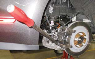
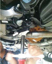
14. Lower the jack that was supporting the sub frame, remove the spring and spring seat. This can be done by inserting a crow bar into the opening and simultaneously pulling down on the crow bar and pulling outward on the spring.
REAR SUSPENSION INSTALLATION
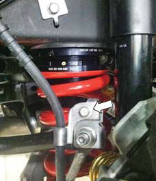
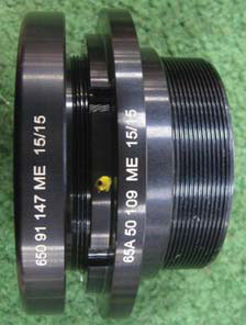
1. If you want to change the height of the rear adjustable spring mount (P/N: 1315-SPRGMNTAA), you must remove the set screw fi rst and then turn the height adjuster and the spring perch to the desired height. Place the rear adjustable spring mount on top of the rear spring (P/N: 1315- 5560-AA). DO NOT OVER TIGHTEN THE SET SCREW. MAXIMUM TORQUE IS 2 Nm.
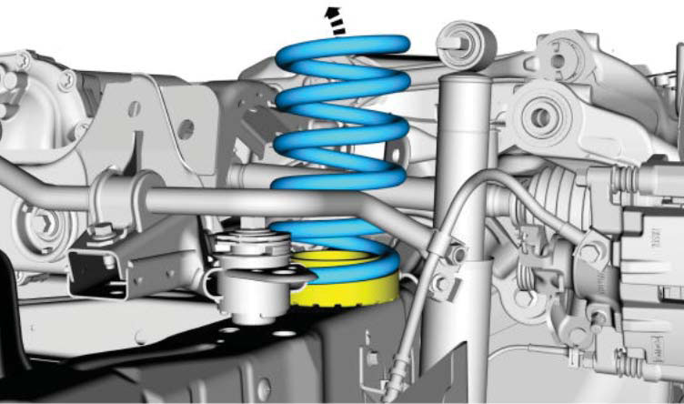
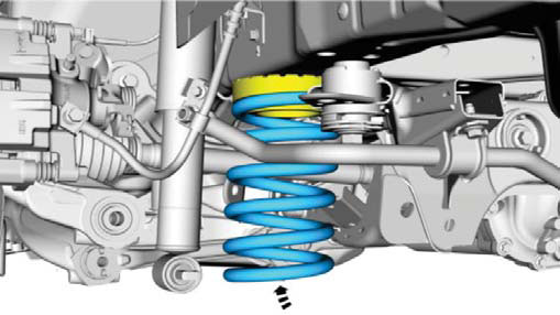
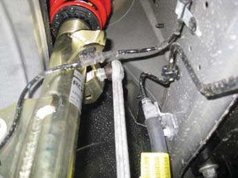
2. With the jack supporting the sub frame, continue to raise it, so there is enough clearance to insert the rear spring (P/N: 1315-5560-AA) and rear adjustable spring mount (P/N: 1315-SPRGMNTAA).
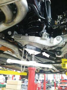
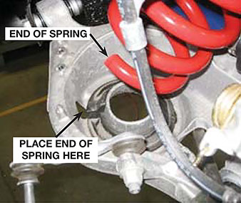
3. Feed the bottom of the spring into position fi rst, as pictured below. Make sure the lower end of the spring is resting against the lower coil spring seat. If it is not, rotate the spring until it is in the correct orientation.
4. Inspect the placement of the assembly once again, then lower the jack down off of the sub frame.
5. On the left side of the shock assembly, fasten the bolt to the sub frame by using the 21 mm socket. Torque to 175 Nm.
6. On the right side of the shock assembly, fasten the right sub frame by using the 21 mm socket and bolt. Torque to 175 Nm.
7. Use a 13 mm socket to fasten the two (2) sub frame bracket bolts. Torque to 55 Nm.
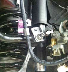
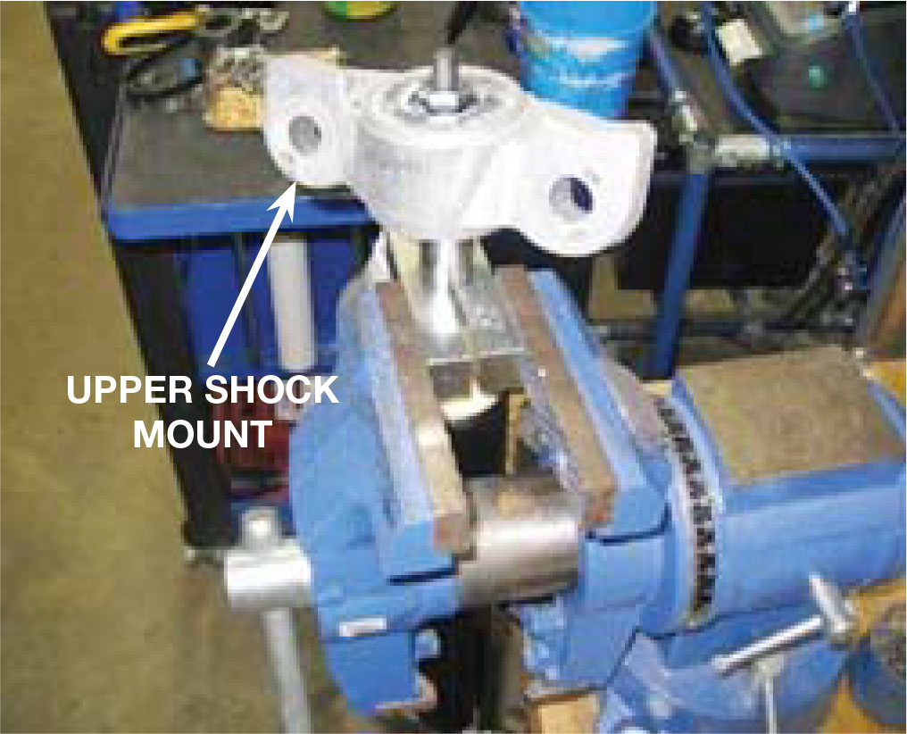
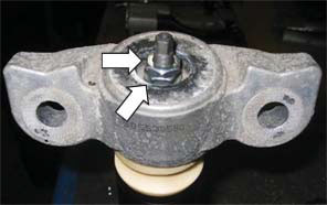
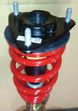
8. Take the upper shock mount from the original shock assembly and place it on the rear shock absorber (1315L3-18125 ). Secure the shock absorber in a vise or similar clamping device to prevent the shock shaft from rotating
Care should be taken to not damage the shaft of the shock. Install the fi rst 17 mm nut and torque to 20 Nm. Install the second 17 mm nut and torque to 20 Nm on the end of the shock shaft.
9. Lower the jack and place it back under the lower control arm, and raise the assembly up 2-4 inches.
10. Position the new shock assembly into place, and hand start the threads of the lower shock bolts to get the threads engaged.
11. Using an 18 mm socket, fasten the two (2) upper shock mount bolts to 90 Nm (the jack may need to be adjusted to get the shock positioned correctly).
12. Go back and tighten the two (2) lower shock bolts to 48 Nm using a 15 mm socket. Remove the jack.
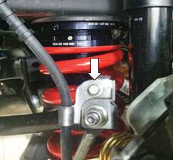
13. Use a 13 mm socket to refasten the brake line bracket back onto the frame. Torque to 10 Nm.
14. Use an 18 mm box-end wrench and a 6 mm hex bit to refasten the sway bar end link bolt nut. Torque to 115 Nm.
15. Use a 10 mm socket to refasten the brake line bracket onto the sway bar link. Torque to 32 Nm.
16. Refasten the ABS brake line by pressing the three (3) clips back on by hand.
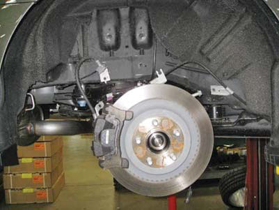
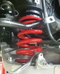
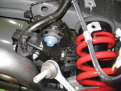
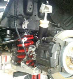
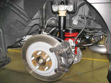
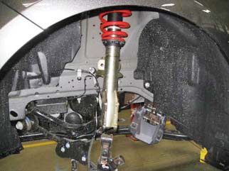
17. Inspect the work to make sure that there are no loose nuts or bolts. The picture below is of the completed rear suspension.
18. Use a 21 mm socket to install the wheel back on the hub and fasten the lug nuts. Torque to 200 Nm.
19. Repeat the rear suspension removal and installation instructions for the other side of the vehicle.
Front Suspension Removal
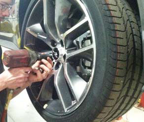
1. Remove the five (5) lug nuts from the front driver side wheel using a 21 mm socket.
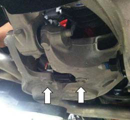
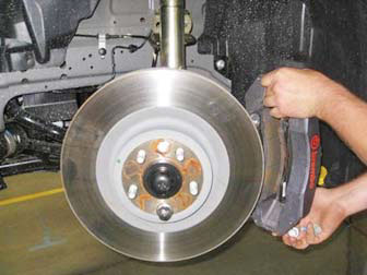
2. Turn the wheel to the right. Remove the two (2) 15 mm bolts on the back of the brake caliper. Set the brake caliper aside and secure it to prevent damage from falling. Pull off the brake rotor and set it aside.
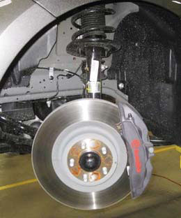
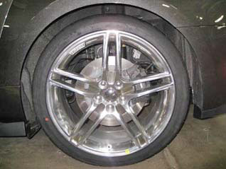
Before
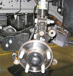
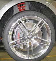
After
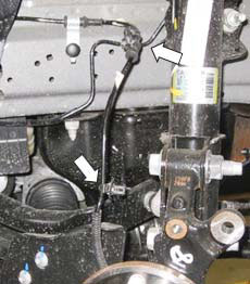
3. Remove the wheel speed sensor with a trim tool by pulling the two (2) clips that are attached to the black cable.
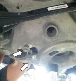
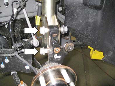
4. Loosen the two (2) 15/16" nuts on the knuckle bolts and back them off until they are fl ush with the end of the stud. This will keep the thread from being distorted while driving out the bolts.
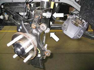
5. Use a hammer and tap out the splined knuckle bolts. Remove the nuts once the splined feature of the bolt is free of the knuckle. Remove the bolts
6. Loosen the top bolt of the sway bar link by using a 17 mm wrench and an 18 mm socket. Push the sway bar link out of the way.
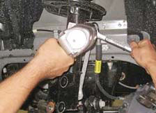
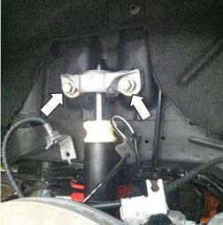
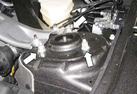
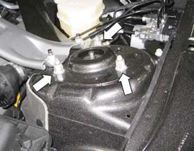
7. Open up the hood and remove the three (3) 15 mm nuts on top of the strut. Remove the entire strut assembly and set it aside.
8. Position the front strut assembly in a spring compressor and remove the factory top spring mount from the strut. Set the factory strut assembly aside.
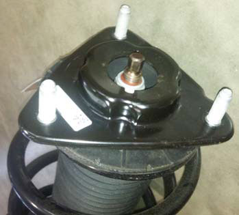
9. Position the new ROUSH strut assembly into the spring compressor and install the factory top spring mount onto the new strut assembly. Seat the spring into the proper position on the mount. Torque the new nut to 50 Nm.
FRONT SUSPENSION INSTALLATION
1. Slide the complete ROUSH front strut assembly (1315L3-18124) into place and fasten the three (3) 15 mm bolts under the hood of the car. Torque to 63 Nm.
2. Realign the knuckle and insert the two (2) splined bolts. Tap the heads of the bolts to get them started. Torque the nut to 235 Nm.
3. Attach the two (2) clips holding the wheel speed sensor back into place.
4. Fasten the sway bar back into position with a 17 mm wrench on the bolt and an 18 mm socket on the nut. Torque to 115 Nm. NOTE: If you have trouble connecting the sway bar link, you can unfasten the passenger side to relieve some of the tension.
5. Install the rotor back on the hub and fasten a lug nut on, fi nger tight, so the rotor does not fall off. Slide the caliper back into position and then torque the two (2) 15 mm bolts on the back of the caliper to 115 Nm.
6. Position the wheel back on and torque the lug nuts to 200 Nm.
7. Follow the front suspension removal and installation instructions for the other side of the vehicle. Congratulations!!! You have completed the installation of the ROUSH Performance Products, Adjustable Suspension Kit.
