 FREE 1 to 3-Day Delivery on Orders $149+ Details
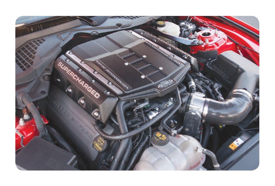
How to Install Edelbrock E-Force Stage 1 Street Supercharger Kit (15-17 GT) on your Ford Mustang
Tools Required
- Jack and Jack Stands OR Service Lift
- Panel Pullers
- Ratchet and Socket Set including 7mm, 8mm (deep), 10mm, 10mm (deep), 12mm, 13mm, 15mm
- 5mm & 6mm Allen Sockets
- 19mm Wrench
- 3/8” Breaker Bar
- Screwdrivers
- 90° Power Drill
- 1.125” Hole-Saw Bit
- Pliers OR Hose Clamp Pliers
- Impact Wrench
- 90° Pick
- Blue Thread Lock Fluid
- O-ring Lube
- Masking Tape
- 90° Drill
- Torque Wrench
- 2 Gallons Motocraft Antifreeze/Coolant VC-3DIL-B Orange Pre-Diluted
WARNING: If your PCM has been programmed with anything other than an SCT programmer, please contact Edelbrock Tech Support at (800) 416-8628 before flashing your PCM. FAILURE TO DO SO COULD RENDER THE PCM INOPERABLE! Edelbrock is not liable for any recovery fees, including but not limited to, replacement of PCM, programmer and/or PCM flashing fees.
PLEASE COMPLETE THIS PROCEDURE PRIOR to starting the installation of your E-Force supercharger system. This will allow our calibration team to complete your calibration file while the installation of your supercharger system is being completed. Manufacturers regularly update the factory calibration, as a result, there is the possibility for delays due to not having access to your current calibration file. This can normally be resolved in 1 business day.
Please e-mail the requested information below to [email protected] with the E-mail Subject as “Calibration Update.” We will complete your calibration and e-mail it back to you as soon as possible. MOST calibration updates will be sent back the same business day. In rare cases, it could take up to 1-2 business days to complete. Please contact our Tech Hot Line at (800)416-8628 if you have any questions or if you need assistance with this procedure.
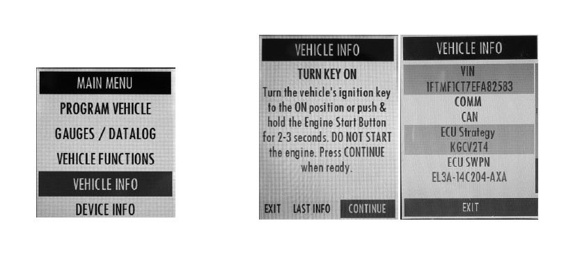
INSTRUCTIONS FOR GETTING THE ECU STRATEGY & SWPN:
With the ignition OFF, connect the supplied SCT X4 Programmer to the OBDII port of the vehicle using the cable included with the SCT programmer.
Once the SCT programmer powers on, it will take you to the Main Menu. Press the down arrow to highlight the “Vehicle Info” option and press the round center button to accept.
Follow the on-screen instructions. When prompted to do so, turn the vehicle’s ignition ON but do not start the engine. Press the round center button to accept. The ECU Strategy and SWPN will be displayed on the following screen.
WARNING: Battery must be sufficiently charged before starting the PCM flashing procedure.
Do not flash the PCM until you are ready to install the supercharger. Once the PCM is flashed, DO NOT START the engine until the installation of the E-Force supercharger is complete.
NOTE: Some of the following images and procedures may differ on RHD (right hand drive) vehicles.
1. Under the front ends of the rear seat, push the two (2) release tabs, one (1) on each side of the seat, and lift up the seat cushion to access the fuel pump connector plug.
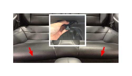
2. Disconnect the fuel pump connector on the driver side.
3. Start the engine and let it run until it stalls. Do NOT reconnect the fuel pump connector yet.
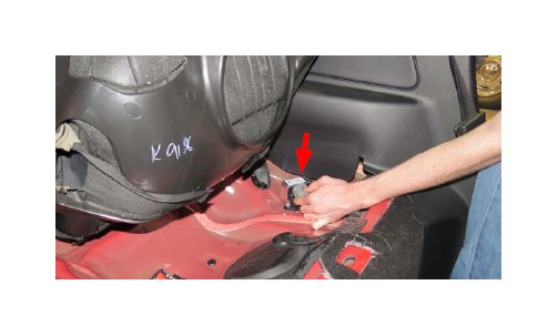
4. Put the vehicle into ACC mode and connect the supplied PCM cable on the handheld programmer to the OBD-II connector located below and left of the steering column.
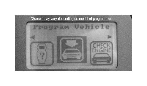
5. Use the directional pad to highlight the Program Vehicle option and press the Select button.
6. Use the directional pad to highlight the Custom Tune option and press the Select button.
7. Read the disclaimer then press Select to continue.
8. Verify that the ignition is in the ‘Key On’ position and that the engine is not running, then press Select.
9. (If applicable) use the directional pad to highlight your vehicle and transmission combination then press Select.
10. Use the directional pad to highlight the Begin Program option then press Select.
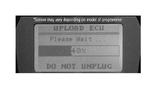
11. Depending on your specific drivetrain configuration, several separate operations may take place during this step. Completion of each operation will cause the progress bar to reset to zero.
12. DO NOT unplug the programmer until prompted.
13. Turn the ignition off when prompted to do so by the handheld programmer.
14. Read the parting message from programmer then press Select to continue.
15. Unplug the programmer cable from the OBD-II port. This concludes the PCM flashing procedure. DO NOT start the engine until the supercharger installation is complete.
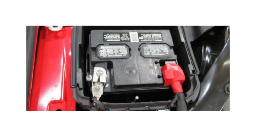
16. Using a panel puller, remove three (3) tree clips securing the battery cover.
17. Using an 10mm socket, remove the negative battery terminal and place it away from the battery. Cover the post to avoid accidental contact during the installation.
18. Using a panel puller, remove eight (8) push pins securing the top radiator shroud. Remove the shroud and set aside.
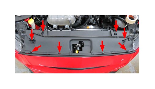
19. Remove six (6) bolts securing the top of the fascia using an 8mm socket.
20. Using a 5.5mm socket, remove two (2) bolts under the weather stripping, one per side.
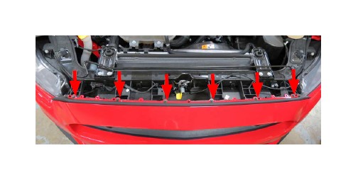
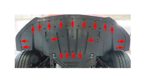
21. Remove sixteen (16) bolts and six (6) push pins securing the splash guard using a 7mm socket and a panel puller. Remove the splash guard and set aside.
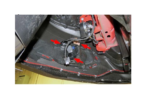
22. Using a panel puller, remove three (3) push pins securing the wheel well liner to the fascia. TIP: Removal of the front wheels is not required but will make accessing the push pins easier.
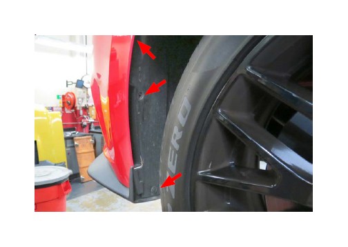
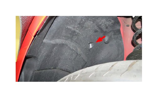
23. There is an additional push pin located just above the tire that needs to be removed.
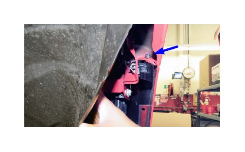
24. Remove two (2) bolts, one per side, securing the fascia to the fender using a 7mm socket.
25. Unplug the fog lamp and signal light connectors (3 lights in total), on both sides of the fascia.
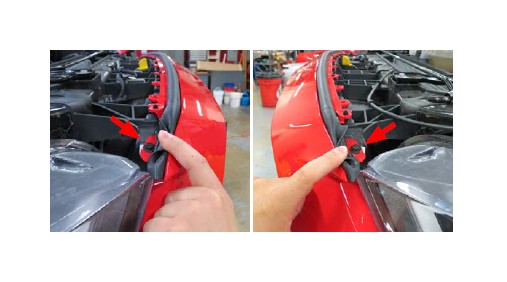
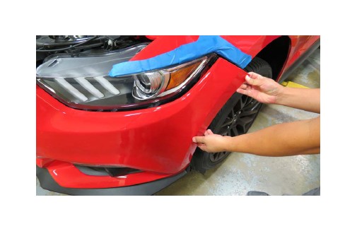
26. Tape up the fender as needed to prevent scratching the painted surfaces. With the help from an assistant, carefully disengage both sides of the fascia by gently pulling the sides outwards. Remove the fascia and set aside.
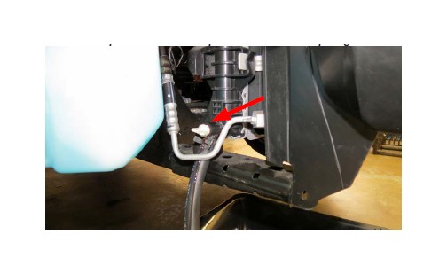
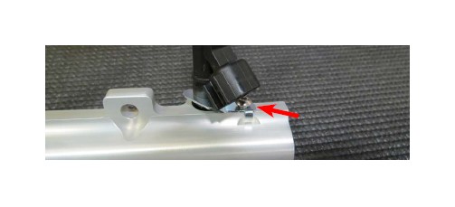
27. Drain the coolant by loosening the petcock located on the passenger side of the radiator. TIP: Placing a hose onto the drain spout will reduce potential coolant spillage.
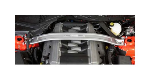
28. Remove the front strut tower brace (if equipped) using a 15mm socket. NOTE: The brace will not clear the supercharger manifold and cannot be used. The bolts securing the brace can be reinstalled once the brace is removed.
29. Gently lift up the engine cover and remove.
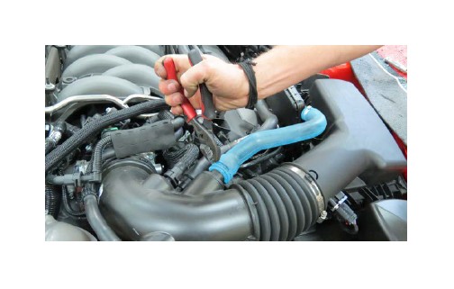
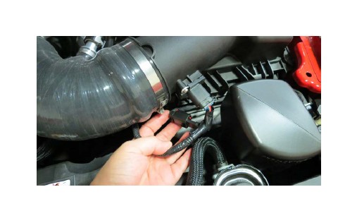
30. Using a hose clamp tool, or equivalent, remove the sound generator hose from the air inlet tube.
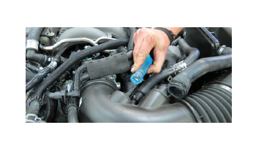
31. Remove the brake aspirator hose from the air inlet tube.
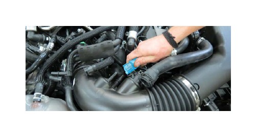
32. Remove the driver side PCV hose from the air inlet tube.
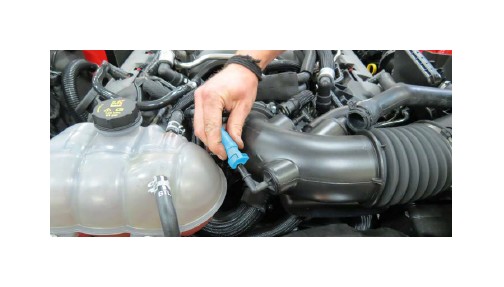
33. Remove the additional brake aspirator hose from the air inlet tube.
34. Disconnect the brake aspirator hose from the manifold PCV hose.
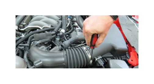
35. Using a flathead screwdriver, loosen two (2) worm clamps securing the air inlet tube and remove.
36. Disconnect the EVAP connectors and fully remove the EVAP hose .
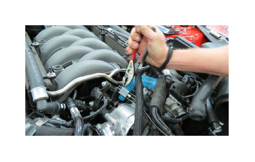
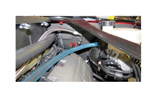
37. Using a hose clamp tool and pliers, remove the brake aspirator hose from the intake manifold.
38. Remove the brake aspirator hose assembly from the brake booster and set aside as it will be reused later.
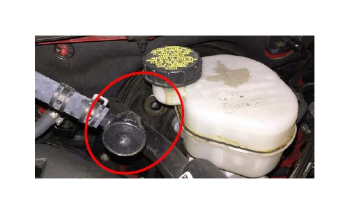
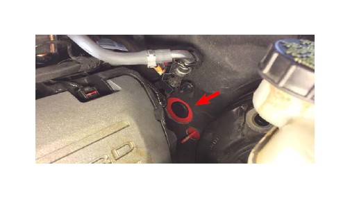
39. Remove the sound generator assembly and plug the hole in the firewall using the supplied plastic grommet plug supplied in Bag # 1.
40. Remove the passenger side PCV hose from the valve cover and the intake manifold.
41. Disconnect the throttle body connector.
42. Using an 10mm socket, remove four (4) bolts securing the heater hose retaining brackets.
43. Remove the retaining brackets and the foam insulators from the fuel rails.
44. Disconnect eight (8) fuel injector connectors.
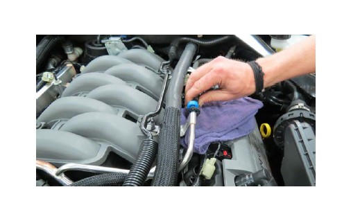
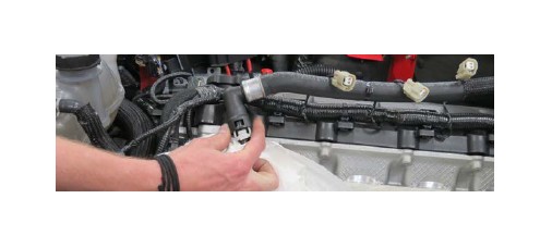
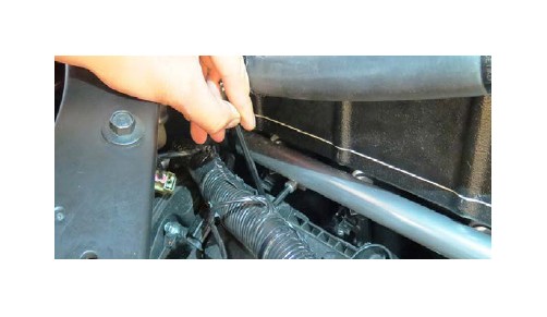
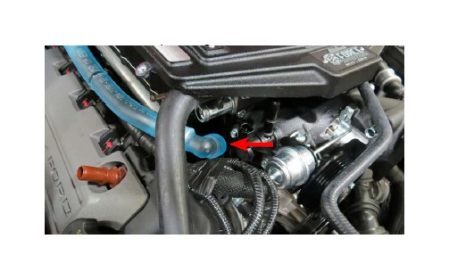
45. Place a rag underneath the fuel input line. Lift up the blue locking tab and disconnect the fuel line from the rail.
46. Using a 10mm socket, remove four (4) bolts securing the fuel rail and manifold. TIP: It’s not required to fully remove the fuel rails.
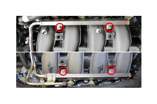
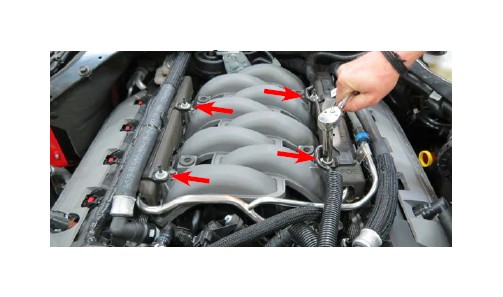
47. Using an 8mm socket, remove six (6) manifold bolts.
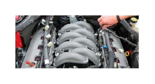
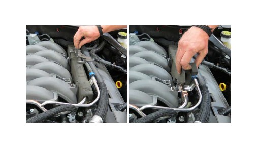
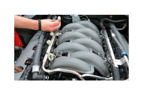
48. With the manifold bolts removed, carefully position the manifold forward and remove four (4) sensor connectors
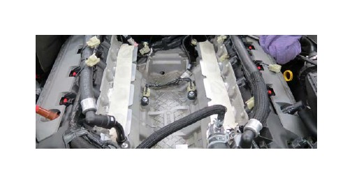
49. Clean the cylinder head flanges as needed and tape up the ports to prevent debris from falling into the ports.
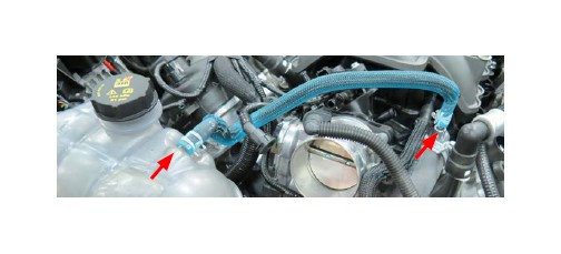
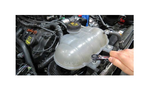
50. Using a 10mm socket, remove two (2) bolts securing the coolant reservoir.
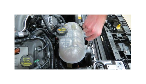
51. Position the coolant reservoir tank out of the way to access the drive belt tensioner.
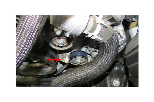
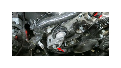
52. Rotate the belt tensioner counterclockwise using a 15mm breaker bar and remove the drive belt.
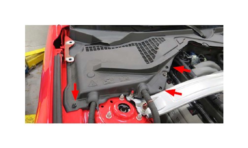
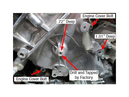
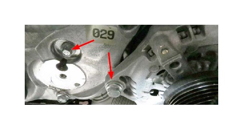
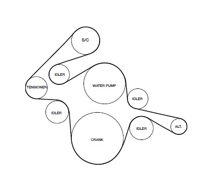
53. Remove the two (2) indicated engine cover bolts on the using a 10mm socket. Using a 90˚ drill and the supplied drill bit, drill out the indicated hole on the front engine cover 1.01” deep. (NOTE: The center hole on some vehicles will already be drilled and tapped by the factory. Please inspect your front cover and avoid drilling this hole if already tapped.) If not already tapped, the hole in the center should be drilled .72” deep. All holes should be tapped to M8 x 1.25 with the supplied tap.
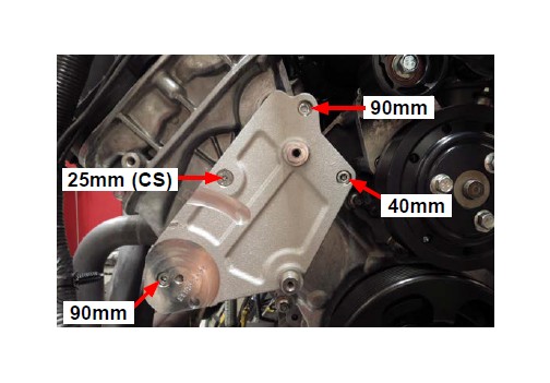
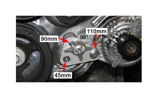
54. Secure the new tensioner bracket to the bosses that were just drilled and tapped with bolts supplied in Bag # 2. (NOTE: When installing the countersunk bolt, place the .045” thick brass spacer between the bracket and the front engine cover if the hole was drilled and tapped by the factory.) Apply blue thread lock fluid to threads and loosely install the following four (4) bolts from Bag # 2, starting with the M8 x 25mm countersunk bolt into the countersunk feature of the bracket located on the left side of the bracket. Install the M8 x 90mm bolt through the engine cover hole at the top, then install the M8 x 40mm bolt through the hole below and to the right. Use an M8 x 90mm bolt in the counter bore feature at the lower left section of the bracket. Proceed by tightening the countersunk bolt first and then tightening the remaining surrounding bolts. Torque all bolts to 22 ft-lbs.
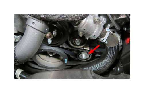
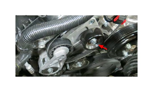
55. Using a 13mm socket, remove the factory tensioner adjacent to the alternator and balancer.
56. Remove both the engine cover bolt using a 10mm socket and the bolt through the ear of the alternator using a 15mm socket.
57. Secure the idler bracket by installing bolts from Bag # 2. The M10 x 110mm bolt through the ear of the alternator, the M8 x 90mm bolt into the top front cover hole, and the M10 x 45mm bolt through the lower hole that was used to secure the stock tensioner. Use blue thread lock fluid on all
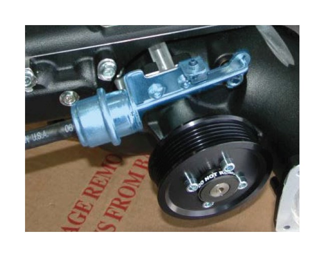
58. Install and secure the 76mm idler pulley onto the center of the idler bracket by using the M8 Washer and the M8 x 20mm bolt supplied in Bag # 3 using a 12mm
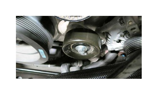
59. Verify that the tensioner is clocked correctly by sliding the index through the hole on the bracket. Install the supplied belt around the tensioner pulley and torque the M10 bolt supplied in Bag # 2 with a 15mm socket to 32 ft-lbs.
60. Using the M8 x 20mm bolts and M8 washers supplied in Bag # 2, install two idler pulleys to the tensioner bracket. The top idler pulley is 65mm and the lower idler is 76mm. Add a small amount of blue thread lock fluid to the threads ONLY, do not allow excess thread lock fluid to drip onto the pulley’s bearings. Torque the bolts to 18 ft-lbs.
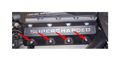
61. Remove the OEM coil covers on each valve cover to access the ignition coils and spark plugs. Unclip each connector and use an 8mm socket to unbolt each coil pack. Label and remove each coil pack so that they are re-installed in the correct cylinder. Remove the spark plugs with a 5/8” spark plug socket and replace them with the supplied spark plugs. NOTE: Gap the supplied spark plugs to .035. Reinstall the plugs and torque them to 9 ft-lbs., then reinstall the OEM coils and coil covers.
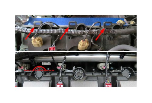
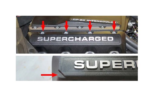
62. Trim off the square coil harness retaining tabs located on the top of both valve covers. File down any rough edges. Also, trim off the top of the rear round edge of the passenger side valve cover. Carefully remove all debris with a shop vac.
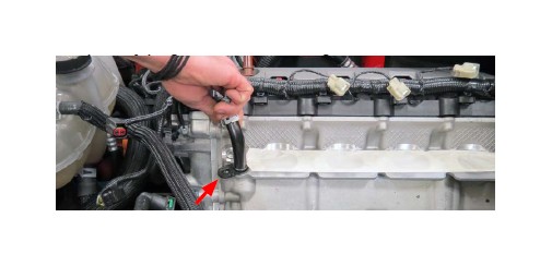
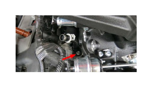
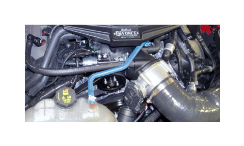
63. Place a rag under the passenger side heater hose and remove the heater hose from the fitting located on the cylinder head. Repeat for the driver side heater hose.
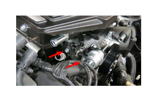
64. Remove the passenger side heater hose fitting with an 8mm socket. Repeat for the driver side heater hose fitting. Temporarily plug the holes with a rag.
65. Using a hose clamp tool, remove the factory coolant bleed hose from the reservoir and bleeder fitting.
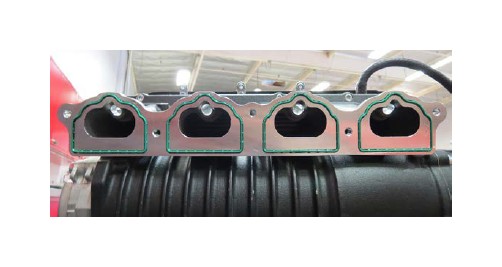
66. Remove the O-ring manifold gaskets from the factory manifold and install them onto the supercharger runners. Apply a small amount of O-ring lubricant to the exposed area of the gaskets. This will help prevent tears during installation of the supercharger.
67. Apply blue thread lock fluid onto the threads of the eight (8) M6 x 12mm SHCS bolts from the side cover kit and loosely screw on the side cover brackets to the underside of the supercharger lid.
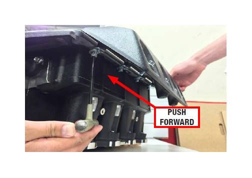
68. For proper bracket alignment, test fit the side covers onto the brackets using eight (8) M6 X 25mm bolts from the side cover kit. While pushing the side covers forward, fully tighten the bracket bolts. Once all brackets are aligned and tightened, remove the side covers.
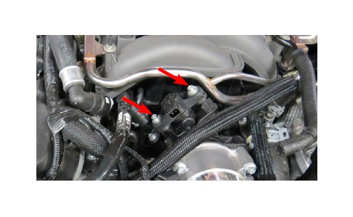
69. Remove the EVAP solenoid from the factory manifold using an 8mm socket.
70. Install the EVAP solenoid to the supercharger manifold using two (2) M6 x 25mm bolts in Bag # 1.
71. Using O-ring lube, install the fuel rail fittings onto the fuel rails. The passenger side rail will have the black plug on the front of the rail, while the driver will have the 180° fitting. Attach the supplied fuel crossover to the rear of both rails.
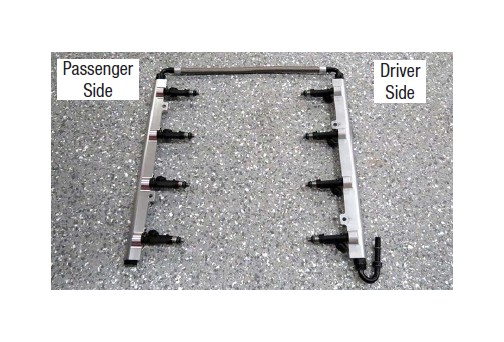
72. Apply O-ring lube to both ends of the supplied fuel injectors, then install them into the supplied fuel rails, oriented so the electrical connectors will face away from the supercharger.
73. Install injector orientation brackets using the M4 x 4mm screws from Bag # 1.
74. Temporally install the fuel rail assembly onto the supercharger manifold.
75. Be sure that the engine bay is clean and free of debris, then remove the masking tape used to protect the intake ports from contamination.
76. With the help of an assistant, carefully lower the supercharger manifold onto the cylinder heads. Be especially careful not to pinch any wires between the supercharger and the cylinder heads. (RHD vehicles will require additional trimming to the plastic cowl for supercharger lid clearance).
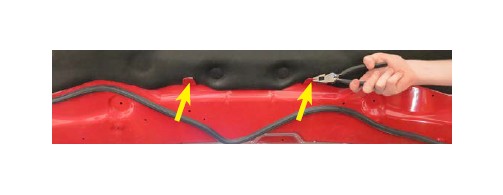
77. Using a pair of pliers, bend the rear hood liner support
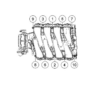
78. Mount the fuel rails and move them away from the supercharger to access the supercharger manifold bolts. Secure the supercharger manifold to the cylinder heads using a 10mm swivel socket to install ten (10) M6 x 30mm intake manifold bolts supplied in hardware Bag # 1. Using the torque sequence below, torque the bolts to 8 ft-lbs.
79. Reinstall the fuel rails and secure the fuel rails using four (4) SHCS M6 x 16mm screws from Bag # 1 and connect the crossover to the driver side fuel rail.
80. Reconnect the injector connectors to the appropriate fuel injectors. WARNING: Never attempt to rotate the injectors.
81. Connect the supplied fuel extension line to the hard line on the firewall. Connect the other end to the 180° fitting on the driver side fuel rail.

82. Reinstall the passenger side heater hose fitting using the factory hardware.
83. Reconnect the passenger side heater hose.
84. Use a 3/8” breaker bar to rotate the tensioner clockwise, finish installing the supplied belt according to the routing diagram shown below.
85. Using the two (2) factory bolts, reinstall the coolant reservoir with a 10mm socket.
86. Install the supplied coolant bleed hose and secure with the factory hose clamps.
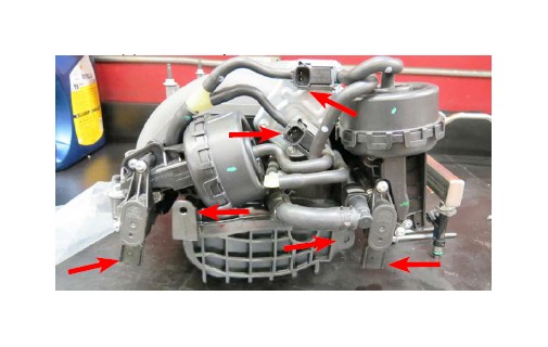
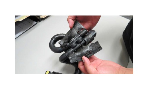
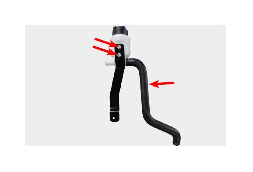
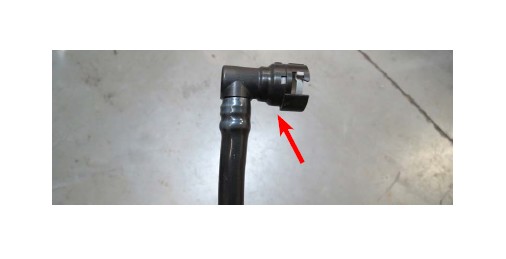
87. Carefully remove the protective foam from the brake aspirator.
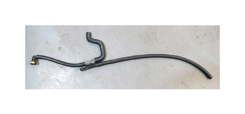
88. Remove the hose that attaches to the check valve and replace with the supplied 3/8” hose. Attach the supplied vacuum cap to the opposite end of the aspirator.
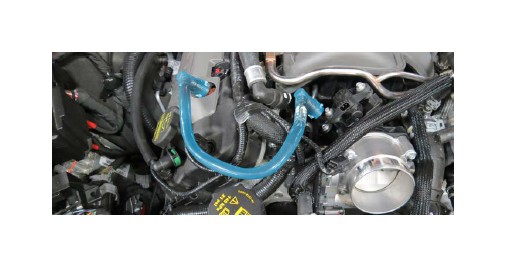
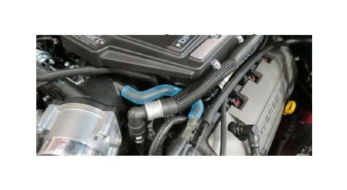
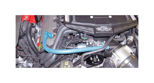
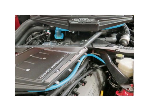
89. Remove the other two hoses from the brake aspirator and attach the Aspirator to Manifold hose and the Aspirator to Elbow hose as shown.
90. Attach the brake booster hose on the aspirator hose assembly to the check valve.
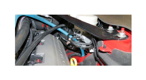
91. Route the Aspirator to Manifold hose under the heater hose and attach to the fitting on the supercharger nose.
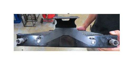
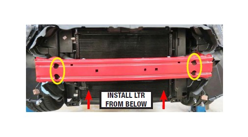
92. Remove the crash beam support bars, if equipped.
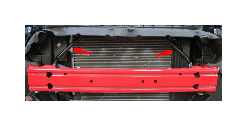
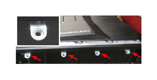
93. Secure the LTR brackets to both sides of the LTR using the M6 x 10mm bolts from Bag # 3.
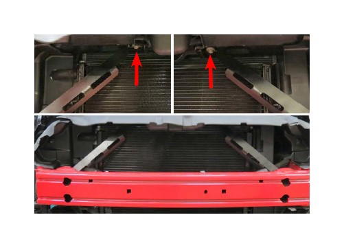
94. Back out the four (4) crash beam bolts (circled in image) but do not remove. Install the LTR assembly from under the crash beam and onto the crash beam support studs. Line up the holes on the LTR brackets with the studs to temporarily
95. Install the supplied beams using the two (2) M8 x 30mm hex flange bolts from Bag # 3, loosely screw in the bolts through the crash beam braces. The lower crash beam braces will sandwich the LTR to the crash beam and be secured using the M8 nuts and washers supplied in Bag # 3. Once all bolts are in place through the braces, fully tighten the bolts and nuts.
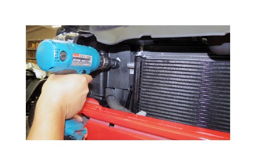
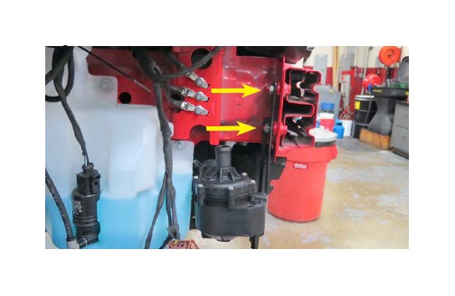
96. Using a drill and a 1 1/4” hole saw bit, drill a hole in the shroud that lines up vertically and parallel with the lower LTR barb.
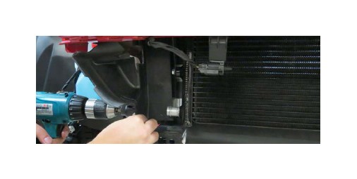
97. Using a drill and a 1 1/4” hole saw bit, drill a hole in the shroud that lines up vertically and parallel with the upper LTR barb. CAUTION: Be mindful of the A/C hard lines behind the shroud.
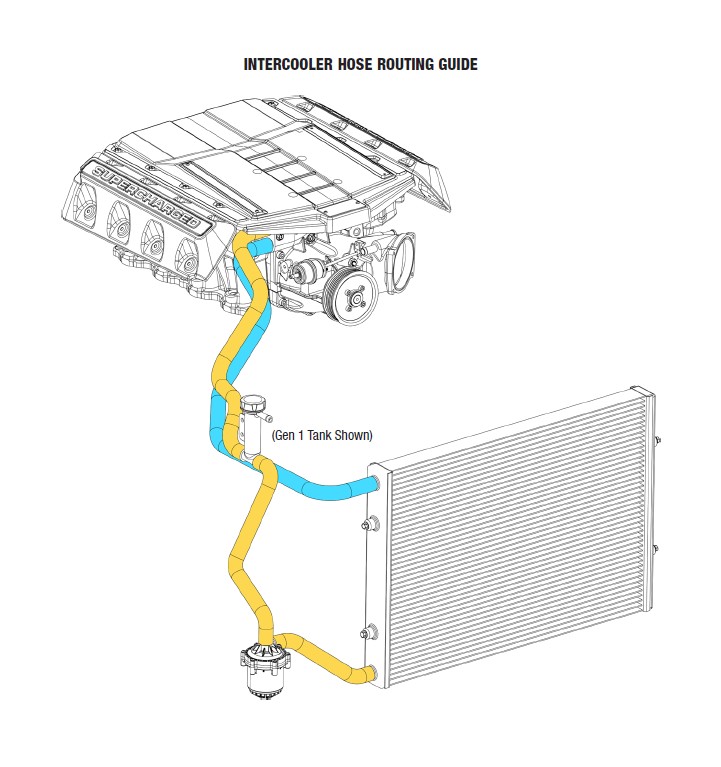
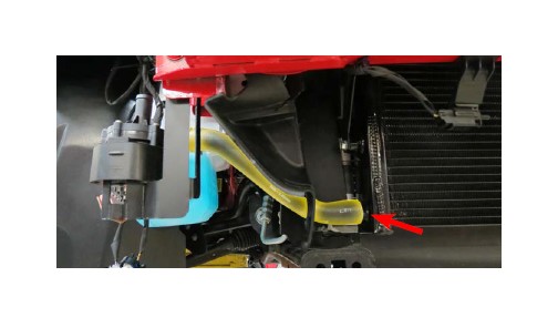
98. Attach the LTR to WP hose to the water pump and secure with a hose clamp from Bag # 3.
99. Feed the hose through the hole in the shroud and secure the water pump to the chassis using the supplied nuts in Bag # 3.
100. Secure the hose to the LTR with a hose clamp from Bag # 3.
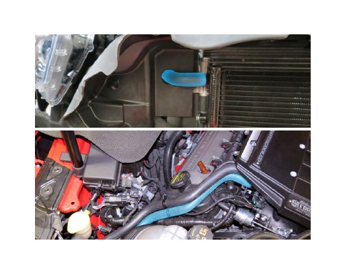
101. Insert the LTR to Manifold hose through the hole on the upper shroud and secure to the top LTR bung with a hose clamp from Bag # 3. Secure the other end to the lower bung on the supercharger manifold.
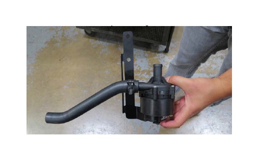
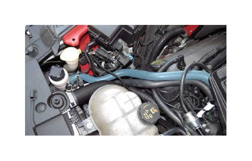
102. Attach the surge tank bracket to the surge tank using two (2) M6 x 10mm bolts from Hardware Bag # 3. Also attach the water pump hose to the surge tank and secure it with a hose clamp from Bag #3.
103. Connect the Water pump to Surge tank hose to the water pump and secure with a hose clamp from Bag #3.
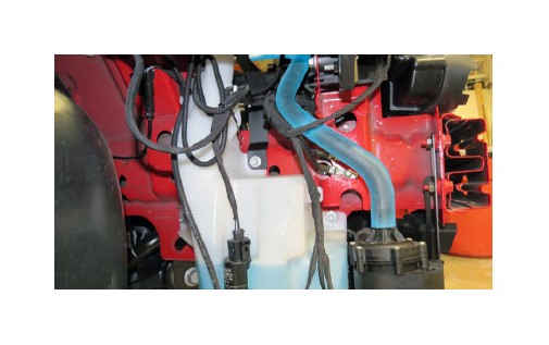
104. Secure the Surge Tank to Manifold hose to the surge tank and manifold using two (2) hose clamps from Bag # 3.
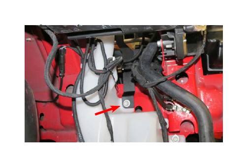
105. Using a 10mm socket, remove the top bolt securing the windshield wiper fluid reservoir. Place the surge tank bracket onto reservoir and secure the bracket and reservoir using the factory bolt.
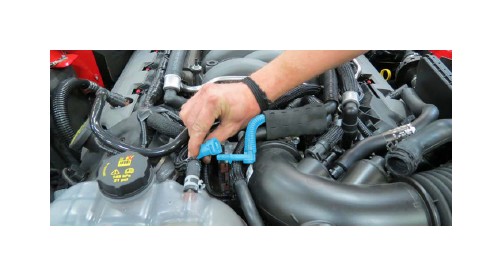
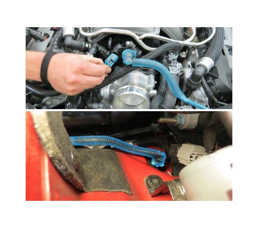
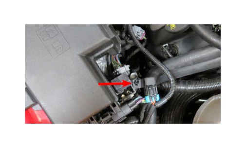
106. Using a razor blade, or equivalent, remove the 90° quick connect fitting on the factory passenger side PCV hose.
107. Attach the 90° fitting onto the supplied 1/2” Cadbar hose. Connect the quick connect fitting to the passenger side valve cover and the other end of the hose to the barb on the supercharger nose.
108. Using a razor blade, remove the 90° fitting on the factory EVAP hose.
109. Connect the factory 90° fitting to the supplied EVAP hose and secure to the EVAP solenoid. Route the other end around the supercharger and down towards the EVAP hard line on the firewall.
110. Connect the supplied straight quick connect fitting on the EVAP hose to the hard line.
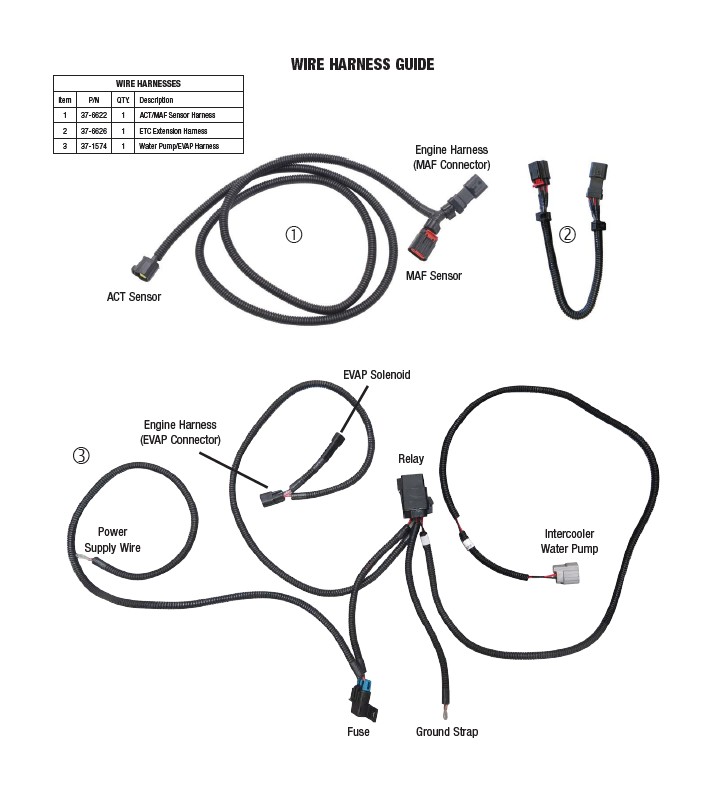
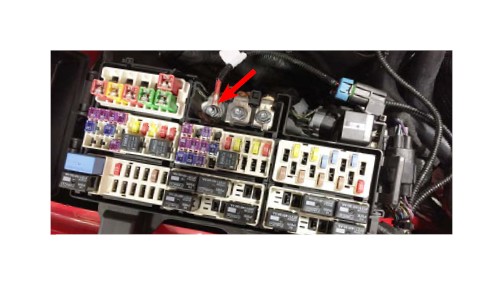
111. Zip tie the Fuse holder on the Water Pump/EVAP Harness onto the top right corner of the fuse box.
112. Open the fuse box and using a 10mm socket, attach the “Power Supply Wire” on the Water Pump/EVAP Harness to the power terminal on the fuse box.
113. Route the “Intercooler Water Pump” end of the Water Pump/EVAP Harness below the fuse box and around the washer fluid reservoir and plug it into the intercooler water pump.
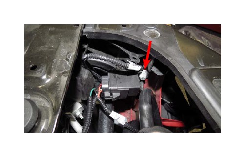
114. Using a 10mm socket, remove the passenger side upper head lamp bolt. Attach the relay AND “Ground Strap” end of the Water Pump/EVAP Harness through the bolt, and screw the bolt back into the frame. NOTE: Use a step drill to enlarge the hole on the relay tab until the bolt is able to pass through the hole.
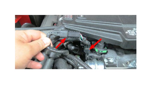
115. Connect the factory EVAP connector onto the “Engine Harness” end of the “Water Pump/EVAP Harness” and the “EVAP Solenoid” end onto the EVAP solenoid.
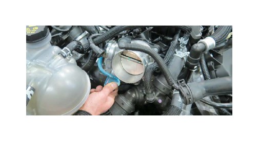
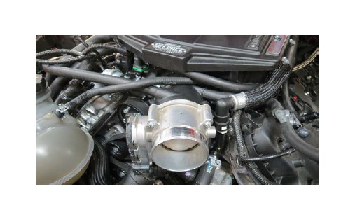
116. Using a 8mm socket, remove the throttle body from the stock manifold and install it onto the supercharger manifold using the factory O-ring gasket and bolts.
117. Remove the airbox lid and replace the factory filter with the reusable Green Filter.
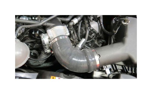
118. Using the factory worm clamps, secure the silicone intake elbow to the throttle body and the air box.
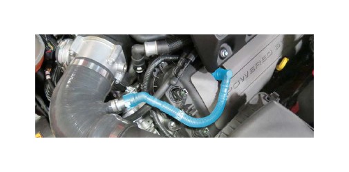
119. Connect the brake aspirator to the lower fitting on the silicone elbow.
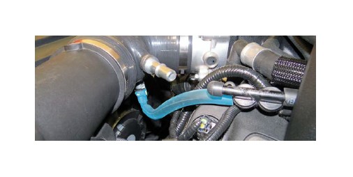
120. Connect the 90° fitting on the supplied driver side PCV hose to the driver side valve cover. Connect the other end to the fitting on the silicone elbow.
121. Using the eight (8) M6 x 25mm bolts from the side cover kit, secure the side covers to the side cover brackets previously installed (See step 67).
Note: The passenger side cover will have a clearance notch. RHD vehicles will require trimming of the passenger side strut brace for clearance.
WARNING: Launching the vehicle may cause wheel hop which will induce engine torquing. The engine movement may cause the passenger side coil/ side cover to make contact with the strut brace. Available aftermarket Wheel Hop Eliminator kits should be considered if this problem occurs. Additional clearance may be required to alleviate any contact in the strut brace area.
122. Install four (4) M6 x 8mm bolts from the side cover kit to both side covers as shown.
123. Plug the MAF/ Temp wiring harness into the Temp sensor located at the back of the manifold on the passenger side. Route the harness from the passenger side to the driver side behind the manifold. Then route the remaining length along the driver side heater hose.
124. Separate the MAF harness connector from the MAF sensor located at the outlet of the airbox. Connect the engine harness to the connector on the MAF/Temp harness then attach the MAF/Temp harness to the MAF Sensor. Reattach the harness to the tab on the airbox.
125. Reconnect the fog lights and indicators, then replace the fascia onto the front of the car.
126. Replace the lower splash shield and secure it with the stock fasteners.
127. Verify that the coolant petcock is closed, then refill the coolant system.
128. Fill the supercharger surge tank with a 50/50 coolant and water mixture. NOTE: Please see “How to Prime the Edelbrock E-Force Intercooler Systems” at the end of these instructions for detailed instructions.
129. Turn the ignition key to the ‘ON’ position.
130. Verify that water is flowing briskly through the recovery tank, then install the cap.
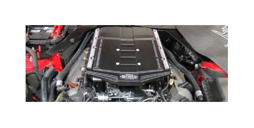
Congratulations on the installation of your new Edelbrock E-Force Supercharger System. If you have any questions, please call our Technical Support hotline and one of our technicians will be happy to assist you.
How to Prime the Edelbrock E-Force Intercooler Systems.
The electric water pump used on this Edelbrock E-Force Supercharger System has a built-in micro-processor that will vary pump cycle speed when air bubbles are present in the system. If a significant amount of air is trapped in the system, the pump may cycle at a slower speed and pulsations are likely to occur resulting in poor cooling performance.
For the best result, it is highly recommended to use a Radiator Cooling System Vacuum Purge and Refill Kit to properly evacuate the air from the intercooler system before filling with a 50/50 mixture of coolant and distilled water. If one is not available, the following procedure will be adequate.
1. Using the Lisle 24680 Spill-Free Funnel, or equivalent, secure the appropriate filler neck adapter to the surge tank.
2. Attach the funnel and fill with a 50/50 mixture of coolant and distilled water until the funnel is half full.
3. Turn the ignition to the ON position and listen for the pump’s electric motor to cycle. Air bubbles will begin to purge from the system as the coolant level drops. Add coolant to the funnel as necessary. NOTE: Do NOT let the coolant level in the funnel run empty as this may introduce air into the system.
4. To build more pressure in the intercooler system, try squeezing the intercooler hoses while the pump is cycling. Building pressure in the system will help purge the trapped air from the intercooler system.
5. Cycle the ignition OFF and wait a few seconds for the pump to come to a stop.
6. Cycle the ignition ON again and repeat until the sound of the electric pump is continuous without any pulsation. NOTE: During water pump start-up, it is normal for a slight pulsation to occur. Once the pump has reached its maximum cycle speed, no pulsations should be present.
7. Periodically inspect the water pump flow after a few drive cycles and re-fill the intercooler system as necessary.
8. Several drive cycles may be required to completely purge the air from the intercooler system. During a drive cycle, the intercooler system will build up pressure as the supercharger temperature increases. Any residual air trapped in the system will gradually bleed out of the surge tank as the system reaches a pressure above 5psi.
WARNING: Always avoid removing the surge tank cap when the engine is hot. The hot coolant is under pressure and may spray out causing burns.
