 FREE 1 to 3-Day Delivery on Orders $149+ Details
2005-2006 Mustang GT CDC Shaker Installation Guide

Shop Parts in this Guide
Read installation instructions before starting and test fit component before painting. The Shaker Hood Trim Ring is molded UV Stable ABS Plastic. To ensure the quality of your vehicle and the product have your Trim Ring painted by a professional automotive painting facility (if applicable). We recommend that paint-curing temperature not exceed 180°F.
Installing the Trim:
1. Raise Hood and remove under hood blanket. Use a fork tool to remove pushpin fasteners. Set hood blanket aside. Close hood and mask off entire area where Shaker opening will be cut out to help prevent paint damage during the cutting process.
2. Measure and mark centerline on the hood. Align template with rear of hood and centerline as noted on template. Tape template securely to top of hood. NOTE: It is very important that the centerline of hood is measured accurately. Make sure to line up centerline of template to centerline on hood.
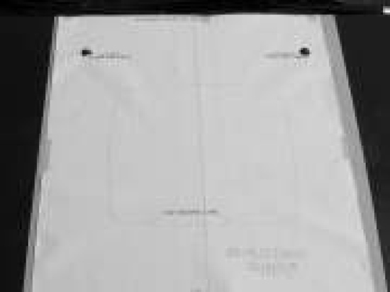
3. With a sharp razor blade or x-acto if available cut through template through the tape and into the paint of your hood. Cutting/scoring the paint on the hood will reduce the chance of paint flake during the cutting process.
4. Remove template from hood and discard. Peel tape from center of Shaker opening leaving an outline of Shaker opening. NOTE: During the drilling and cutting process elevate the hood far enough to ensure no damage will occur to engine components. Place a blanket over engine to catch metal shavings.
5. Center punch and drill a starter hole for Shaker opening with a 1” hole saw. Cut Shaker opening following the outline. Hint: Stop cutting half way around opening and place masking tape over cut line for support (this will help prevent some vibration) then finish the cutting process.
6. Remove tape from hood. Clean area of hood around the cut opening with Isopropyl (rubbing) Alcohol where Upper Trim Ring will be placed. It is imperative that any wax be removed from the vehicle at the tape contact area for proper adhesion of TrimRing.
7. Apply 3m Acrylic Bonding tape (part #950011) to bottom side of Upper Trim Ring. Sand area with 80- 120 grit sand paper clean with supplied Alcohol pack and allow time to dry apply supplied Adhesion Promoter and allow time to dry apply 3m tape. Press on tape with fingertips to set tape.
8.Peel 3”-4” of the red backing from the Upper Trim Ring (part # 115051) and place in hood opening. When proper placement is achieved finish peeling the red backing from acrylic bonding tape and press on trim ring to set tape to hood.
9. Raise and prop hood.
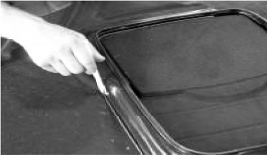
10. Temporarily reinstall hood blanket to bottom of hood using original fasteners and trace inside of Upper Trim Ring on to the hood blanket. Remove hood blanket and set on bench. (A white grease pencil works best.)

11. With the hood blanket on the bench line up the Lower Trim Ring (part # 115050) with the line traced from the upper. Now trace the outside of the Lower Trim Ring onto the hood blanket. Note: Trim Ring will follow contour of the hood blanket when properly positioned the hump is toward the rear. Remove Lower Trim Ring and measure ½” from the outer line toward the center of the hood blanket and mark one more line this is the line you will cut using a sharp blade. Cut out blanket.
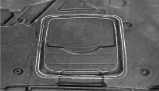
12. Reinstall hood blanket with factory retainers.
13. Install the Lower Trim Ring onto the Upper Ring flange squeeze until trim rings snap together. The Lower Trim Ring will hold the hood blanket in place around the opening.
14. There are two small holes that are predrilled in the front and rear of the Upper and Lower Trim Rings (4 total). Use #183011 rivets to secure the Upper and Lower Trim Rings together.
Installing Shaker
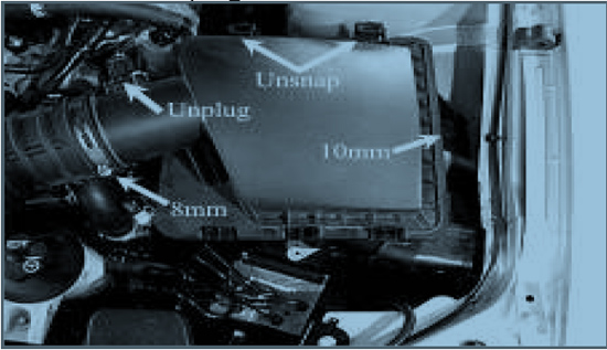
1. Remove filter housing from vehicle. Unplug Mass Airflow Sensor at this time.
2. Slightly bend the oil dipstick tube toward the driver side wheel to create clearance for the engine cover.
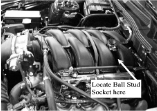
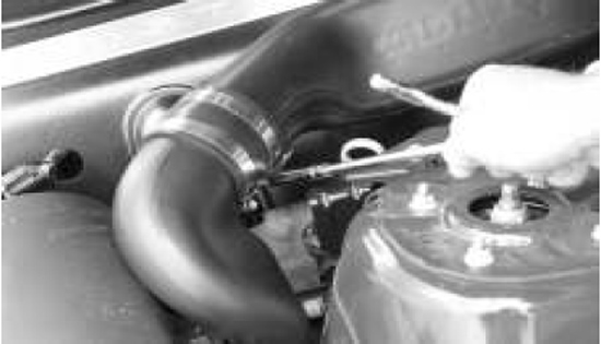
3. Mount the Ball Stud Socket Bracket with Socket (part # 116055) to the intake manifold with the U-Clamp (part # 116054). Use a drop of Thread Locker on the setscrew. Align the edges of the Socket Bracket as show in Figure below.

4. For optimal fitment of “U” clamp depending on the build date of your vehicle some cars require trimming of the lip from the bottom side of the intake manifold with a razor blade this will allow the clamp to fit flat against the manifold.
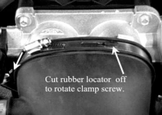
5. Relocate screw location of the factory air inlet clamp at the throttle body. Loosen the clamp screw and cut off the rubber knobs on the air inlet tube (top and bottom of tube) allowing the clamp to rotate counter clockwise. Rotating this clamp allows clearance needed for the engine cover.
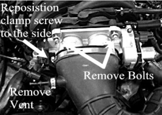
6.Remove the two upper bolts securing the throttle body to the intake manifold and unplug vent tube from the air inlet.
7. Attach the 4 Drain tubes (part# 183027) to the engine cover and secure them with the supplied Zip Ties (Part# 116053).
8. Install the Engine Cover Assembly onto the intake manifold. IMPORTANT: Route drain tubes away from moving parts and hot surfaces! Place the Ball Stud mounted to bottom of the Engine Cover into the Ball Stud Socket. Run the factory throttle body bolts through the front Engine Cover Bracket through throttle body and into their factory locations (torque to 89lb-in). Route the vent tube through passenger side hole on the front of Engine Cover and plug into its factory position on the air inlet tube. Route the Mass Air Flow Sensor connector through the hole on driver side cover.

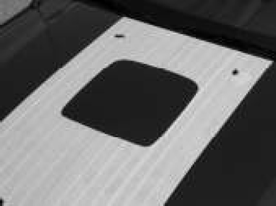
9. Using the Air Box Template mark and cut the hole in the lower air box.
10. Snap Lower Air Tube (part #115053) into air box.
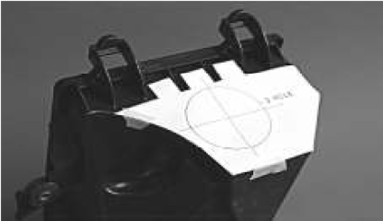
11. Caution: It is very important that the hole in the air box is precisely cut to 3”. We recommend using a 2 ¾” hole saw then file by hand to achieve proper diameter.
12. Place the 3” Coupler with clamps (part # 115056) onto Upper Air Tube (part#115054).
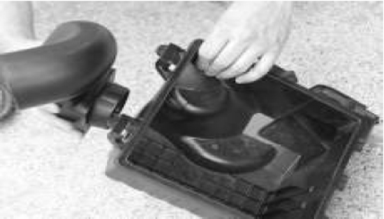
13. Reinstall air filter housing into vehicle.
14. Reconnect Mass Air Flow connector to sensor.
15. Slide Coupler half way over Lower Air Tube (part #115053) and tighten clamps.
16. Secure Drain Tubes (part #115058) using Zip Ties (part #116053). Route Drain Tubes away from moving parts and hot surfaces.
17. Congratulations your installation is complete!

Installation instructions provided by Classic Design Concepts (CDC).
