 FREE 1 to 3-Day Delivery on Orders $149+ Details
JLT Cold Air Intake Installation Guide ('96-'04 GT)
Installation Time
60 minutes
Tools Required
- Phillips and Flat Head Screw Driver
- 8mm and 10mm Sockets
- Car Jack
- Jack stands
Installation
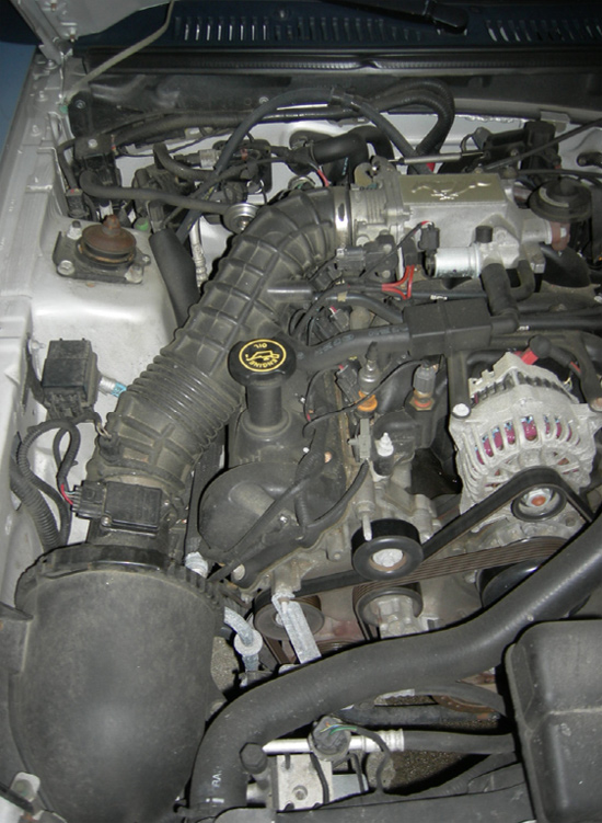
Stock Factory Air Intake
1. As with any work in the Engine Bay - Disconnect Negative Terminal from Battery.
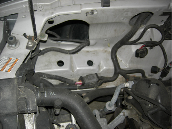
2. Take a flat head screwdriver or 8mm Socket and loosen the metal ring clamp from around the upper intake pipe & throttle body. (Pic 2 - Red Arrow)
3. Remove vacuum hoses from upper intake pipe. (Pic 2- Yellow Arrow)
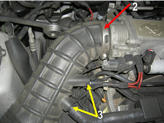
Picture 2
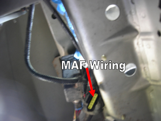
4. Disconnect the MAF wiring harness. (Pic 3 - Red Arrow).
5. If you intake has a separate IAF Sensor disconnect the IAF wiring harness, and remove from the intake. (Pic 3 - Yellow Arrow)
6. Take a flat head screwdriver or 8mm socket and loosen metal clamp from lower intake and MAF adapter. (Pic 3 - Green Arrow) Remove intake piping.
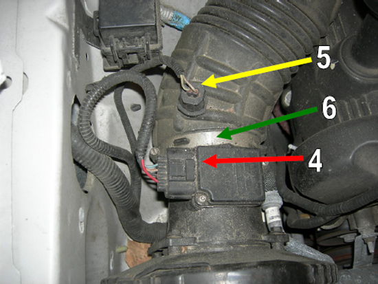
Picture 3
7. Un-hook the O-ring clamp from the air filter housing. (Pic 4 - Red Arrow) Remove MAF Adapter and set aside.
8. Using a 8mm socket remove the bolt securing the air filter housing from the wall and remove air filter housing. (Pic 4 - Yellow Arrow).
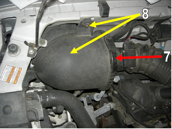
Picture 4
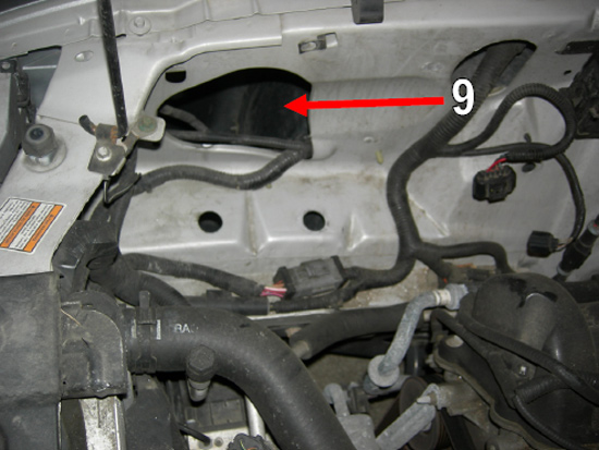
9. You will now see the hole in the fender wall where your new JLT Intake will relocate your air filter. (Pic 5 - Red Arrow).
10. Take this time while everything is out to clean the area. Remove any leaves or dirt that may be left after removal. You are now ready to begin installing your new intake.
Picture 5
11. There are different ways of installing your new intake, the following worked the best for me.
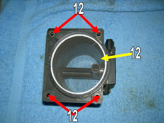
12. Take your MAF Adapter and remove the circular ring by using a 10mm socket and unscrew the 4 bolts. (Pic 6 - Red Arrows). Remove the screen from the MAF Adapter as well. (Pic 6 - Yellow Arrow).
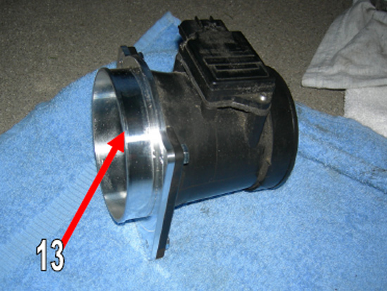
13. Take the supplied MAF Adapter Plate and secure it to the MAF Adapter by using a 10mm socket and supplied bolts (Pic 7 - Red Arrow).
Picture 6
Picture 7
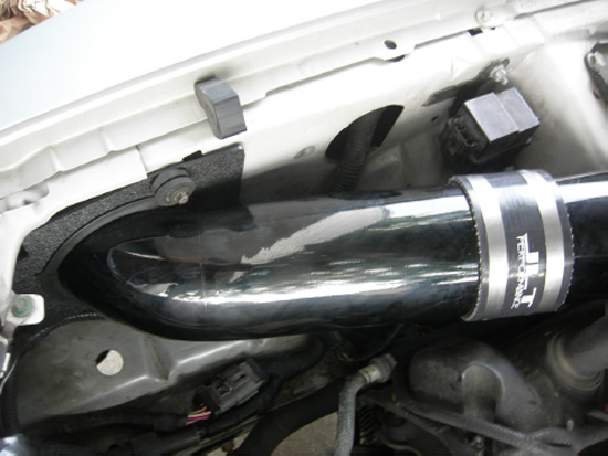
14. Attach the silicone reducer hose to the upper intake pipe using the small metal clamp. You may use a flat head screwdriver or 8mm socket. Make sure you are able to get to the clamp tightener device in case you have to loosen the clamp to maneuver the intake. (Pic 8 - Red Arrow)
15. Attach the larger silicone hose the end of the upper intake pipe using the larger metal clamp.
Picture 8
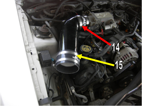
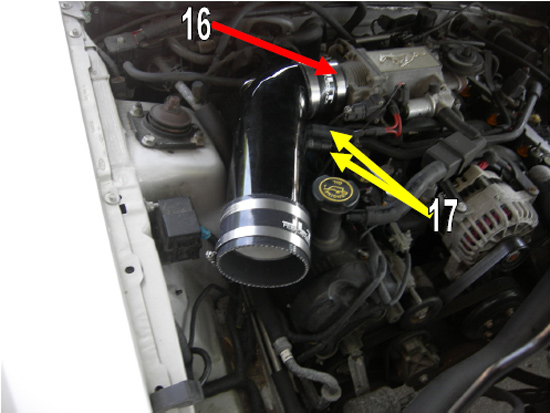
16. Attach the upper intake pipe to the throttle body using another small metal clamp. Make sure you are able to get to the clamp tightener device in case you have to loosen the clamp to maneuver the intake. (Pic 9 - Red Arrow)
17. Attach the vacuum hose back to the upper intake to the correct nozzles. The lower vacuum tube will require you to remove the plastic piece that is in the hose already. (Pic 9 - Yellow Arrow) Time to move to the lower intake pipe!
Picture 9
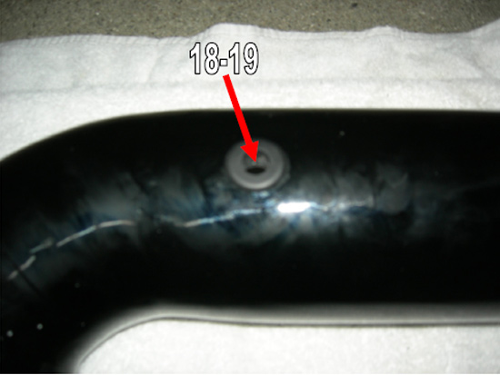
18. (Skip this step if you do not have a separate IAF Sensor) If you have a separate IAF Sensor you will need to drill a 3/4 inch hole in the lower intake. You may place the hole anywhere on the lower half but placing it underneath the pipe is recommended so you are not able to see it.
19. Place the supplied grommet into the hole. If you can get your arm in the pipe, it will be easier to get the grommet in place.
Picture 10
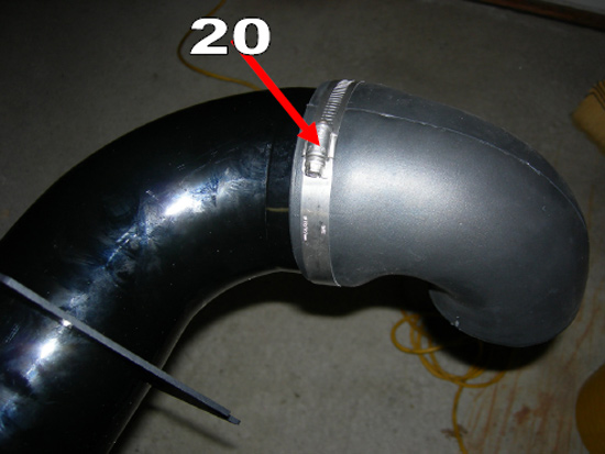
20. Using the 90 Degree Elbow, attach it to the end of the lower intake pipe so that it is facing perpendicular to the pipe. It may be hard to attach the elbow since it is rubber, to help you may use soap and water, or place it in the microwave for 20seconds (be careful taking it out as it will be hot!) I recommend to get the Elbow on as much as you can, you will see a line in the intake to where you can match it up. Once attached us a large metal clamp to hold the elbow onto the pipe.
Picture 11
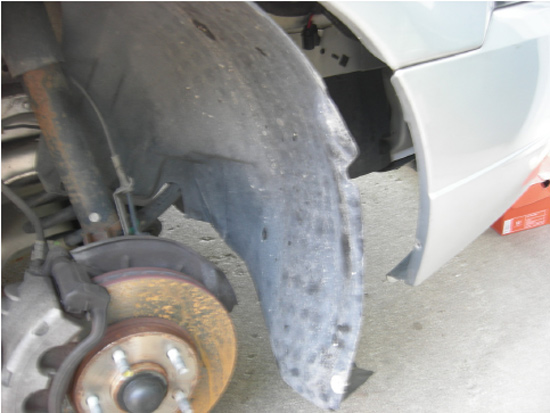
21. At this stage it is now best to test the fitment of the lower intake to see if the elbow is pointed downward into the fender wall. To do so, jack up your car and remove the wheel. Remove the Phillips head screw holding on the fender wall splash guard and pull it back as much as you can. There are also 3 black plastic holders that you may need to remove if you do not have enough room.
Picture 12
22. Take some masking tape and put tape around the edging of the hole in the fender wall. This will keep you from scratching you intake on the edges. Take the lower intake pipe with the elbow attached and twist it through the hole. Once you have the lower intake lined up with the upper intake look into the fender wall from the wheel well to see in the elbow is coming down at a 90 degree angle, if it is your perfect, tighten the metal clamp on the intake. If you are not at a 90 degree angle remove the intake pipe and adjust the elbow properly. ( I did this about 3-4 times)
Picture 13
23. Once you have the elbow in the correct position take the MAF adapter and connect it to the elbow using a small metal clamp. Make sure the side going into the elbow is the black part and not the metal adapter plate. You will want to make sure that theme Wiring Harness plug is facing the fender wall so that you can plug the wiring back in. Make sure you can get to the clamp if you have to turn the MAF to connect the harness.
Picture 14
24. Once you have the MAF installed on the elbow. Take the black plastic square with the mounting hole and use the supplied black weather striping to put around the inside circle so that it will not scratch the intake pipe. Slide the square onto the lower intake pipe so that the rough plastic side is facing away from the fender wall. At this time take your MAF Wiring and put it threw the fender wall hole so that you are able to plug it into the MAF Harness. Take the intake pipe and“screw” it into place by inserting the intake pipe into the fender wall hole and twisting so that the MAF is facing down towards the ground.
Picture 15
Picture 16
25. At this time you may connect the lower intake pipe to the upper intake pipe. Use a larger metal clamp to secure the connection, try to push in the lower intake as much as possible to get a good fit. Check under the fender wall to make sure everything is aligned correctly, you make then use the bolt that was holding the air filter hosing to the wall, to secure the black plastic square piece to the fender wall, try to get it as flush as possible.
Picture 17
26. Once everything is tightened, you will need to install the air filter to the MAF Adapter Plate. Take the filter under the fender wall and push the filter onto the MAF Adapter Plate, and tighten using the supplied metal clamp on the filter. While you are there plug in the MAF Wiring into the harness. You may now re-attach the fender wall splash guard.
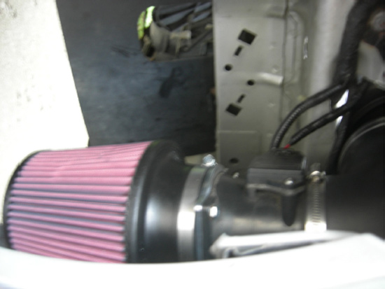
Picture 18
27. Take the IAF Sensor you removed from the intake and install it into the hole you drilled. Attach the IAF Wiring to the sensor.
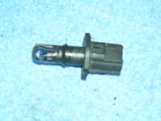
Picture 19
28. Make sure all the clamps are tightened to prevent leaks. Make sure your vacuum hoses are attached to the upper intake ports. Make sure the intake is not rubbing on the strut wall or oil cap. If everything looks good, re attach your negative battery terminal. Start the car and listen for any air or vacuum leaks, a vacuum leak could cause the check engine light to come on. If your check engine light does come on double check all your connections and make sure they are tight. Once complete just listen to the beautiful sound of your new JLT Cold Air Intake.
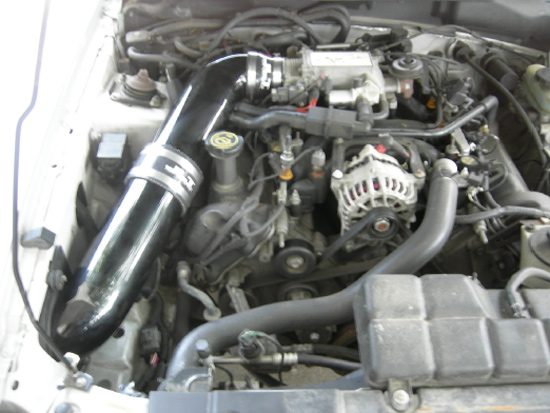
Finished Installation
Installation instructions provided by AmericanMuscle customer Adam Buehner
