 FREE 1 to 3-Day Delivery on Orders $149+ Details
How to Install Baer Track-4 Front Brake Kit - Red (94-04 All) on your Ford Mustang
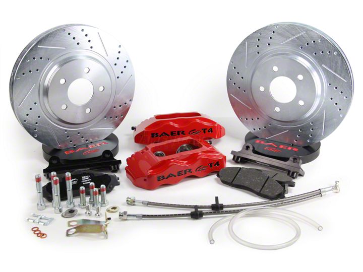
Shop Parts in this Guide
ATTENTION: Read this before going any farther! Returns will not be accepted for ANY installed PART or ASSEMBLY. Use great care to prevent cosmetic damage when performing wheel fit check.
Notices – Read and Follow BEFORE ATTEMPTING INSTALLATION
• All installations require proper safety procedures and protective eyewear.
• All installations assume basic mechanical skill and a factory service manual for the vehicle on which the installation is to be performed.
• All references to LEFT side of vehicle always refer to the Driver’s side of the vehicle.
• Any installation requiring you to remove a wheel or gain access under the vehicle requires use of jack stands appropriate to the weight of the vehicle. In all cases Baer recommends jack stands rated for at least 2-tons.
• A selection of hand tools sufficient to engage in the installation of these products is assumed and is the responsibility of the installer to have in his/her possession prior to beginning this installation. All installations, which require removal of hydraulic hoses and/or bleeding of the brakes, require appropriate fitting/line wrenches, as well as a safety catch can and protective eyewear. Other than these items, if unique or special tools are required they are listed in the section for that step.
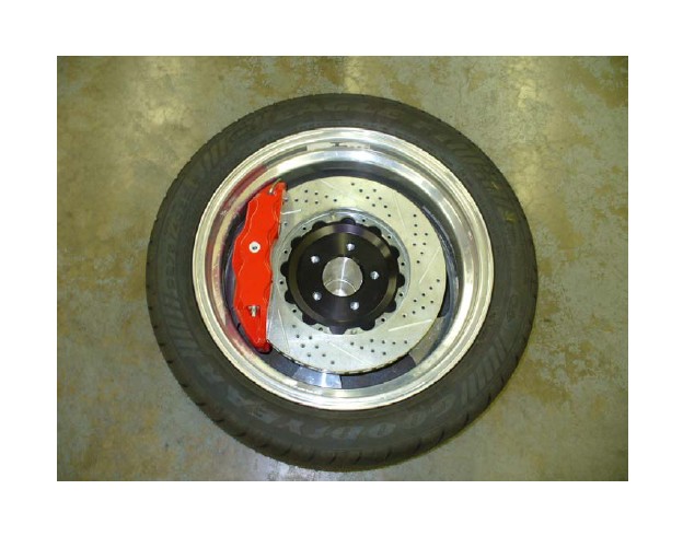
• ALWAYS CONFIRM WHEEL FIT PRIOR TO BEGINNING INSTALLATION OF ANY BRAKE S Y S TEM OR “UPSIZED” ROTOR UPGRADE! In addition to already having checked fit using the Baer Brake Fit Templates available online at www.baer.com, always place the actual corner assembly or a combination of the caliper assembly fit onto the rotor into the actual wheel to reconfirm proper clearance is available between the caliper and the wheel before proceeding with the actual installation. Returns will not be accepted for systems that have been partially or completely installed. Use extreme car when performing wheel fit check to prevent cosmetic damage.
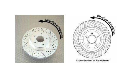
• When installing rotors on any Baer Products be sure to follow the direction of rotation indicated on the rotor hat area with either an arrow, or an “L” for left, or an “R” for right, or both. “L” or left, always indicates the driver’s side of US spec vehicles.
Images shown are “L” left rotors.
• A proper professional wheel alignment is required for any system requiring replacement of the front spindles, or tie rod ends. Follow factory prescribed procedures and specifications unless otherwise indicated.
• At all times stop the installation if anything is unclear, or the parts require force to install. Consult directly with Baer Technical Staff in such instances to confirm details. Please have these instructions, as well as the part number machined on the component that is proving difficult to install, as well as the make, model, and year (date of vehicle production is preferred) of your vehicle available when you call. Baer’s Tech Staff is available from 8:30-am to 5-pm Mountain Standard Time (Arizona does not observe Daylight Savings Time) at 602 233-1411 Monday through Friday.
Disconnect the fluid hose at the frame and cap the hardline with the supplied vinyl cap. Remove the hose lock and pull the hose from the bracket.
Remove the two bolts retaining the caliper to the spindle and remove the caliper.
Remove the rotor and thoroughly clean the hub and caliper mount surface to allow the Baer rotor to seat properly on the hub.
Baer recommends removal of the factory debris shield. This will impede air flow to the inside of the rotor which allows cooling air to circulate. Removal will enhance cooling of the rotor.
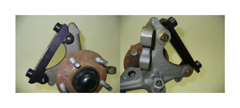
Install the intermediate bracket to the outboard side of the spindle using the supplied 12mm x 35mm bolts. Tighten snugly for later removal while centering caliper.
Install the correct side Baer rotor and secure with two lug nuts using a washers to avoid scratching the hat.
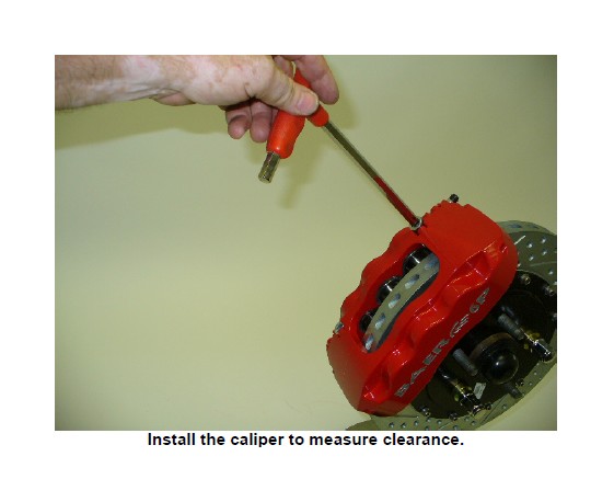
With pads removed, install correct caliper (bleeder screw points up), using the allen bolts provided. Snug these bolts for measuring caliper alignment.
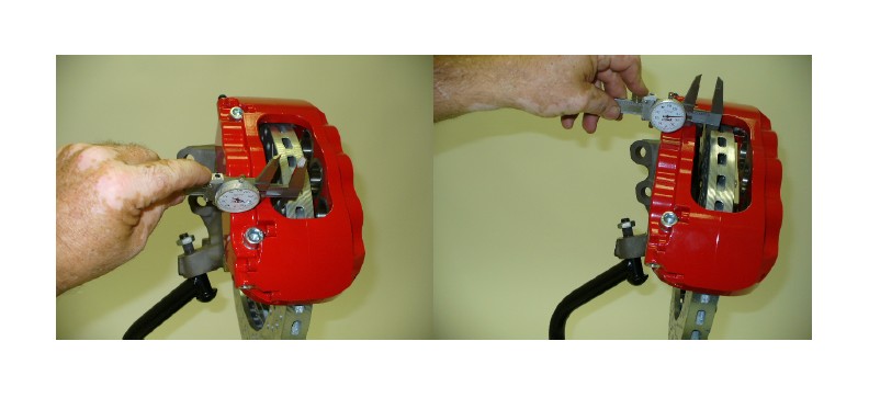
Measure the gap from the rotor to caliper body at 4 points, top inside and outside, bottom inside and outside. Write down all measurements. Subtract the top inside measurement from top outside. This will require a shim at the top bracket bolt equal to half of this difference to center the caliper. For instance, inside measurement of .865”, outside of .905” has a difference of .040 which would require a .020” shim installed to center. Do the same with the bottom measurements to center this also. Getting these gaps as close as possible, within .005”, will keep the possibility of excessive noise to a minimum. This may require different thickness shims top and bottom. Refer to photo next page for measuring points.
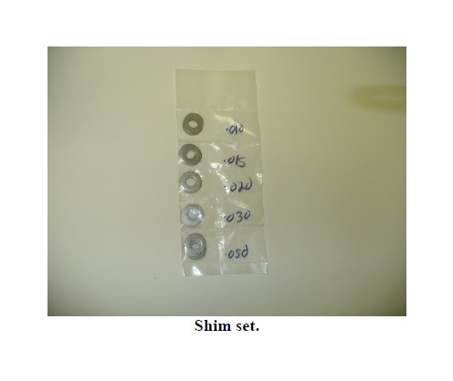
Select the desired shims from the set provided. Remove the caliper. Loosen the bolts from the intermediate bracket. Install the appropriate shims, removing one bolt at a time, and snug the same bolts for fit check.
Reinstall the caliper and recheck gap measurements. Re-shim if necessary. When proper shimming has been achieved, remove caliper. Take the bolts from the intermediate bracket one at a time keeping the shims in place and replace with the 12mm x 35mm bolts. Torque to 85 ft-lbs. Caliper bolts torque to 85 ft-lbs also.
If you do not have access to a dial caliper, these measurements can be made with pads installed using a feeler gauge between the rotor and pad. Take measurements from top inside and outside, then bottom inside and outside. Minimum clearance is .010” between pad and rotor, but equal gaps at all four locations is best.
To insert the hose adaptor in the frame bracket, the positioning tab for the original hose will need to be filed slightly to allow the fitting to slide into the bracket. A rat tail file is the easiest tool for this.
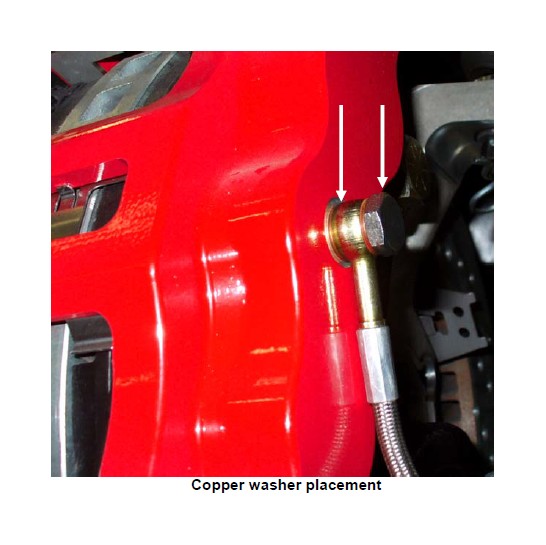
Install the steel braid hose with one copper washer on each side of the banjo fitting. See photo below. Finger tighten the banjo bolt. Connect the hose to the hardline and install the hose lock. Position the hose to avoid interference with the wheel and suspension components. Tighten fitting and banjo bolt to 15-20 ft-lbs.
Repeat these steps for the other side and recheck all attachment points and fittings.
Refer to Bleeding and Rotor Seasoning procedures contained on a separate sheet or on our website, www.baer.com.
For service components and replacement parts contact your Baer Brake Systems Tech Representative.
