FREE 1 to 3-Day Delivery on Orders $149+ Details
How to install a BBK High Flow Aluminum Fuel Rail Kit on your 1999-2004 Mustang
Installation Time
3 hours
Tools Required
- 1/2”& 5/8” Spring-Lok type fuel line disconnect tools
- 11/16” wrench
- 12, 10, & 8mm sockets
- 5mm & 5/32” Allen wrenches
- White lithium grease
- Teflon tape
- Anti seize
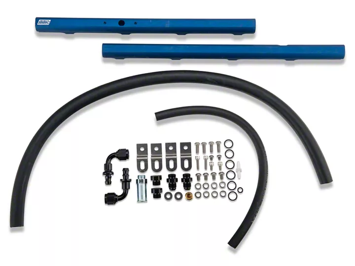
Shop Parts in this Guide
Warning!
Fuel system is under pressure. You will need to relieve this pressure in Step 4. Please read instructions carefully!
Installation
Step 1
Disconnect negative battery terminal.
Step 2
Remove air inlet hose assembly from the throttle body.
NOTE
The throttle body does not need to be separated from the plenum for the next step. You can remove them together as one piece.
Step 3
Disconnect the throttle cables, unplug the sensors and vacuum connections from the intake plenum (also known as the intake elbow), unbolt the EGR valve from the driver side and unbolt and remove the intake plenum assembly.
NOTE
In the next step you will release the fuel pressure in the fuel rails. Be sure to extinguish any open flames and disable any spark or ignition sources, or other potential fire hazards around the work area.
Keep in mind that Gasoline vapors are more flammable than gasoline itself.
Step 4
Hold a rag around the shrader valve on the front of the driver side rail, and then bleed off any fuel pressure by depressing the valve with a small screwdriver or pick tool.
Step 5
Unplug the electrical connections from the fuel injectors and fuel pressure sensor.
Step 6
With a 5/8” Spring Lok removal tool, disconnect fuel feed line from the fuel rails.
Step 7
Use an 8mm socket to remove the bolts that attach the fuel rails to the intake manifold.
Step 8.
Remove the fuel rails and injectors by simply lifting them straight up.
NOTE
Now is the time to inspect your fuel injector tips and O-rings. If they are damaged, replace them. Damaged O-rings can cause a fuel leak.
Step 9
Remove the fuel pressure sensor from the driver side rail.
Step 10
Apply a touch of white grease to all of the supplied O-rings and to the O-rings on the fuel injectors.
Step 11
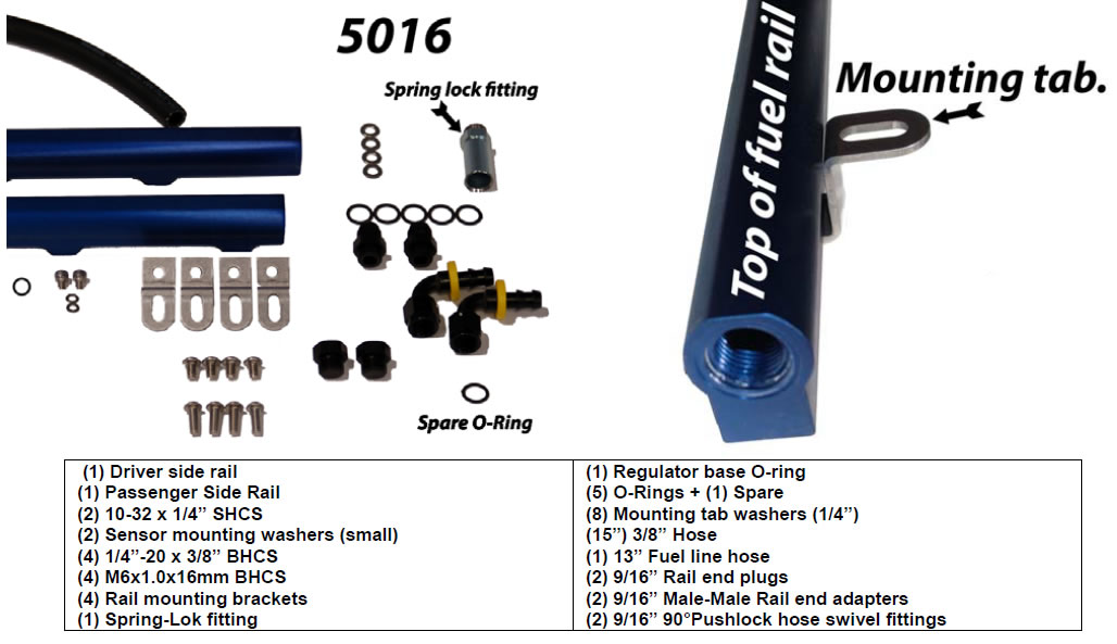
Place (1) O-ring over the ends of the (2) rail end caps, the (2) rail end adapters, and the (1) 5/8” Spring Lok fitting. Remove the (2) O-rings from the pressure switch. Install the (1) supplied small O-ring into the groove closest to the sensor head.
Step 12
For both rails, install an end cap on the front of the rail and a -6 rail end adapter on the rear of each rail and attach the rail mounting tabs with the supplied 1/4”-20 bolts. DO NOT USE THE SUPPLIED WASHERS HERE!
NOTE
Each rail mounting tab has a round hole and a slotted hole. The round holes will attach to the rails. The slotted holes will attach to the intake manifold. Use the supplied washers at the intake manifold end only.
Step 13
Install supplied Spring Lok fitting into the side of the passenger rail.
Step 14
Insert (4) injectors into the passenger side rail.
Step 15
Install passenger side rail and injectors by guiding the tip of each injector into its respective bung in the intake manifold. Secure the rail to the intake manifold using (2) supplied bolts and (4) washers.
NOTE
To ensure clearance between the fuel rails and ignition coils, use (1) of the supplied washers under the mounting tabs and place (1) over the threaded portion of each bolt that go through the tabs at the intake manifold.
NOTE
Take extreme care when installing the small button head cap screws (BHCS) into the fuel rail. Using the wrong length will penetrate the fuel rail and ensure a fuel leak. In addition, these screws can easily cross thread.
Step 16
Install original fuel pressure sensor to driver side rail with supplied O-ring using the supplied 10-32 x 1/4” BHCS’s Measure these screws from the bottom of the head to the end first to ensure you are using the correct hardware here!
Step 17
Insert (4) injectors into the driver side rail.
Step 18
Install driver side rail and injectors by guiding the tip of each injector into its respective bung in the intake manifold. Secure the rail to the intake manifold using (2) supplied 6mm bolts and (2) washers.
Step 19
Assemble the crossover hose by pushing the barbed ends of the supplied 90° - 6 fittings into the ends of the hose.
Step 20
Tighten the crossover hose onto the threads of the rail end adapters on the back of both rails.
Step 21
When routing the crossover hose, be mindful of hot EGR tube it must pass by. Route so no contact is made with the EGR tube.
NOTE
Route the stock fuel feed line under A/C line and connect to the 5/8” Spring Lok fitting on the side of the passenger rail.
Step 22
Reconnect the negative battery terminal.
Step 23
Without starting the engine-Turn the ignition key to the ON position for 3-4 seconds, (primes the fuel system) then OFF 3 times and return to the ON position. Check all connections for fuel leaks. Correct any leaks before starting!.
Step 24
Re-install the intake elbow and re-attach all connections.
Step 25
Re-install air inlet tube.
Step 26
To avoid a possible CHECK ENGINE light activation, Start the engine and let it idle for about 5 minutes, then drive the car at part throttle for about 5 minutes before applying heavy or full throttle. Otherwise, any air bubbles/pockets that may have entered the system will cause the CHECK ENGINE light to come on and will need to be reset with a proper OBD II tool.