FREE 1 to 3-Day Delivery on Orders $149+ Details
How to Install BMR Adjustable Sway Bar Kit - Red on your Mustang
Installation Time
3 hours
Tools Required
- Hydraulic jack and jack stands
- Wrenches and Sockets – 7mm, 17mm, 18mm, 24mm
- 10MM Allen socket
- Long extension for sockets
- 13mm socket
- Allen wrench – 6mm, 3/16

Shop Parts in this Guide
1. Lift the front of the vehicle and safely support with jack stands under the cradle.
2. Remove both front wheels and tires.
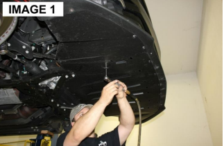
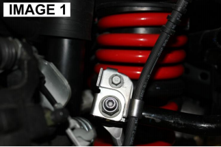
3. Using a 7mm socket, remove all of the small screws that retain the underbody plastic cover as shown in IMAGE 1. There are also various clips that can be removed with a flat head screwdriver.
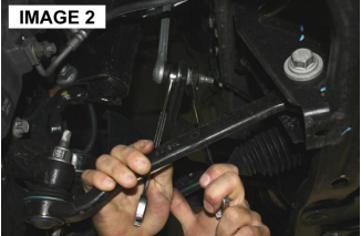
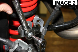
4. Using a 17mm and 18mm wrench, remove the end links as shown in IMAGE 2.
5. Remove the driver’s side tie rod at the spindle using an 18mm socket. Knock it loose from the spindle using a brass hammer or tie rod removal tool.
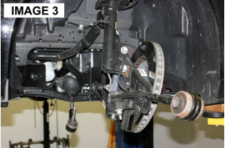
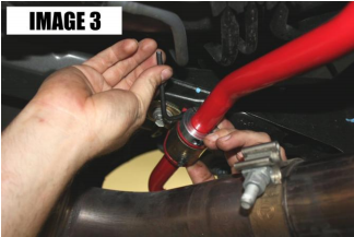
6. Remove the radius rod bolt using a 24mm socket and then swing the entire spindle and radius rod out of the way as shown in IMAGE 3.
7. Using a ratchet with an 18mm socket and long extension, remove the sway bar saddle bolts on the cradle through the top of the engine bay. Note: On the driver’s side one of the bolts is located under the alternator and needs to be removed with an 18mm wrench through the wheel well.
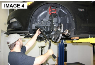
8. Pull the sway bar out the driver’s side wheel well, rotating as necessary until the bar is completely out. IMAGE 4
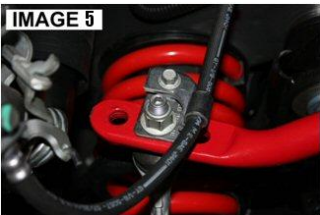
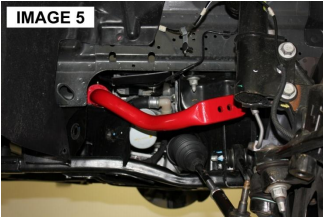
9. Install the BMR sway bar the same way, rotating as necessary until it is in position. It is possible to install the sway bar upside down however it will not fit properly. Installed correctly the bar should match IMAGE 5.
10. Lube the insides of the BMR supplied polyurethane bushings and install them over the sway bar. Place the saddles over the bushings, lining them up with the mounting holes.
11. Install the supplied 12mm Allen bolts and tighten them with a 10mm Allen socket.
12. Re-install the tie rod and the radius rod. Tighten all bolts.
13. Re-install the underbody plastic. 14. Re-install wheels/tires. Lower vehicle.
SB045 INSTALLATION INSTRUCTIONS
Lift the rear of the vehicle and safely support with jack stands under the cradle.
2. Using a 10mm wrench or socket, remove the brake hose bolts out on the sway bar end link brackets as shown in IMAGE 1.
3. Using the 6mm Allen wrench to hold the center of the end link, remove the nut using an 18mm wrench as shown in IMAGE 2. Duplicate for the other side.
4. Using a 13mm socket, remove the (4) bolts that retain the sway bar bushings to the sub-frame. Remove the sway bar.
5. Assemble the BMR supplied polyurethane bushings and saddles onto the new sway bar and install the sway bar using the factory mounting hardware. Assemble the 2-piece aluminum thrust washers over the bar on the inside of the bushings as shown in IMAGE 3. Tighten with a 3/16” Allen wrench.
6. Torque mounting bolts to 24 ft/lbs.
7. Position the supplied 2-piece clamps over the sway bar on the inside of the mounting bushings. Slide them up against the bushing as shown in IMAGE 4 and tighten using a 3/16” Allen wrench.
8. To re-use the brake hose brackets on your BMR sway bar, rotate the bracket as shown and mount as illustrated in IMAGE 5. Tighten the end link nut using the 6mm Allen wrench and 18mm wrench. Tighten the 10mm brake hose bolt.
9. Using a grease gun, lube the polyurethane bushings with synthetic grease. Lower vehicle.
10. Lower vehicle.