 FREE 1 to 3-Day Delivery on Orders $149+ Details
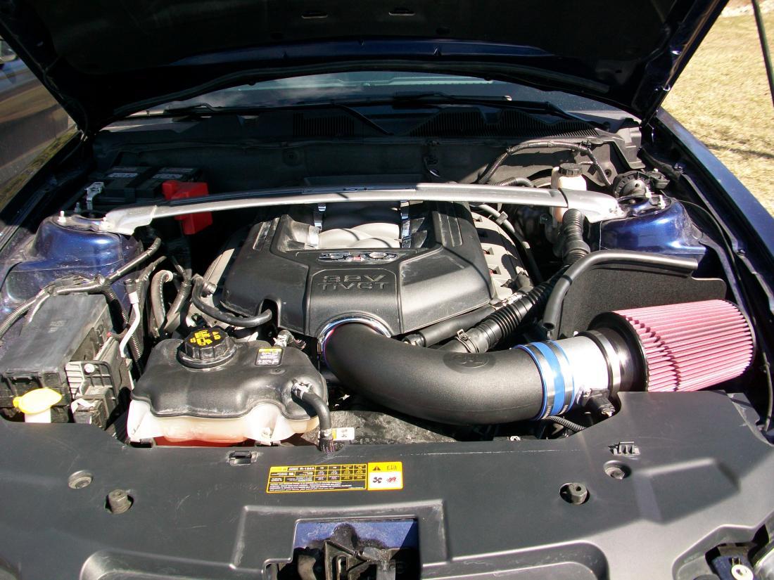
How to Install a C&L Cold Air Intake for 2011-2012 Mustang GT
Installation Time
1 hours
Tools Required
- 10mm socket, socket wrench with extension, 13mm deep well socket, pliers or channel locks, socket driver for kit supplied T-20 torx bit, Phillips head screwdriver, and two flat head screwdriver.Fig.1
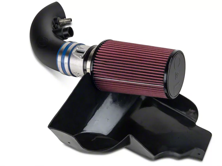
Shop Parts in this Guide
Installation
1. Remove the stock air filter assembly
- Remove strut bar assembly using 13mm deep well socket and wrench for the four nuts holding it to the strut towers and life bar straight off.Fig. 2 (passenger tower nuts removed)
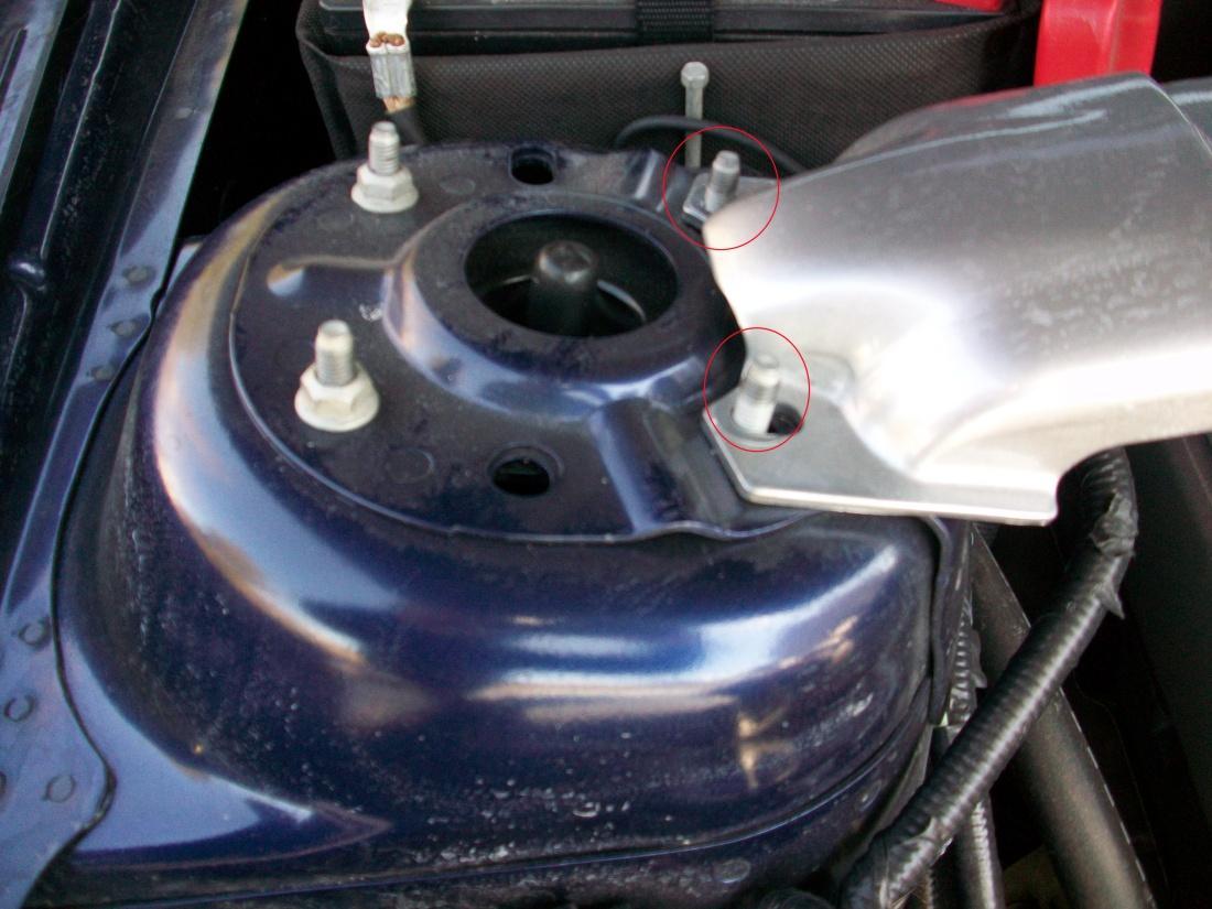
Figure 2
- Remove engine cover by lifting straight up on it by starting with one end (until it releases from the mount) and then moving back to the other end.
- Cover is held down by rubber snaps with two on each side of the engine cover.
Fig. 3 (Cover removed driver’s side
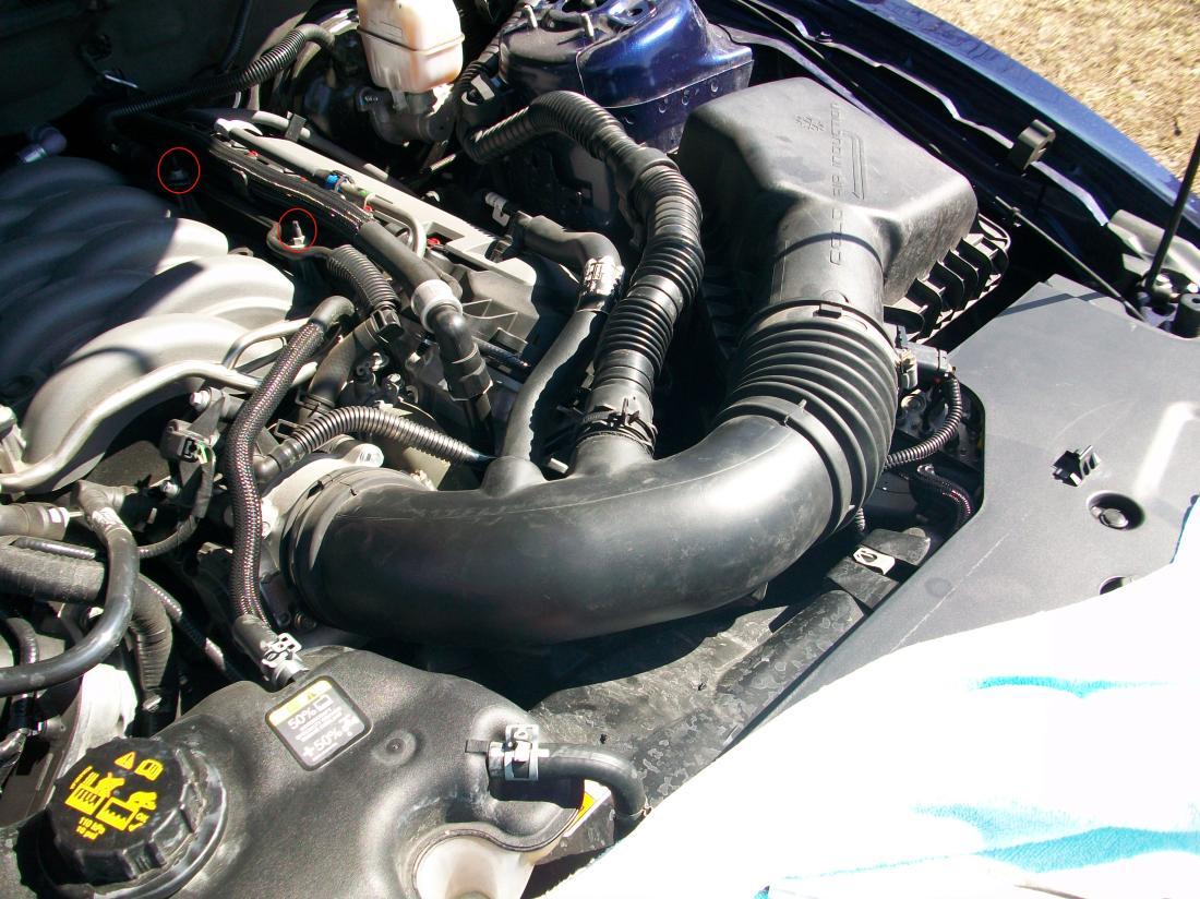
Figure 3
- Loosen the clamp that secures the stock inlet house to the throttle body using a medium flat head screwdriver.Fig.4 (Locations)
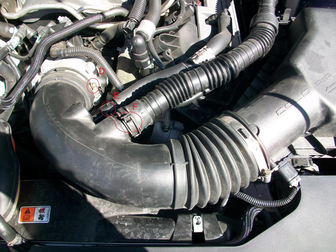
Figure 4
- Disconnect the vacuum house that goes from the valve cover just to the right of the throttle body.
- Push on the small tab holding the fitting in place over the boss of the inlet pipe
- Move this tab over with your thumb and pull connector away towards the driver’s compartment.Fig. 4.e.ii
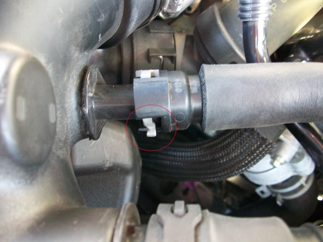
Figure 5
For automatic equipped vehicles there will be a smaller fitting next to the valve cover vent tube.
- Remove from stock intake by pushing down on the yellow tab with your thumb while pulling towards the driver’s compartment.
- Remove the noise transmission tube connector.
- With channel locks or pliers, squeeze the two tabs of the spring loaded clamps together.
- It will lock itself in the ‘open position’.Fig. 4.g.ii
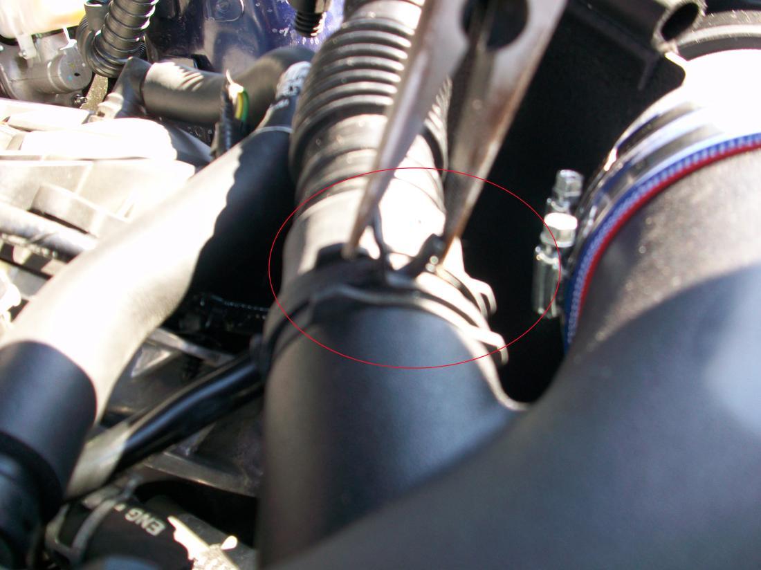
Figure 5
Pull away from the stock intake towards the driver’s compartment and disconnect fastener from the backside of the stock intake box.
Disconnect the MAF sensor located on the front of the air filter housing.
Slide the red tab on the bottom of the connector towards the front of the vehicle.Fig.5
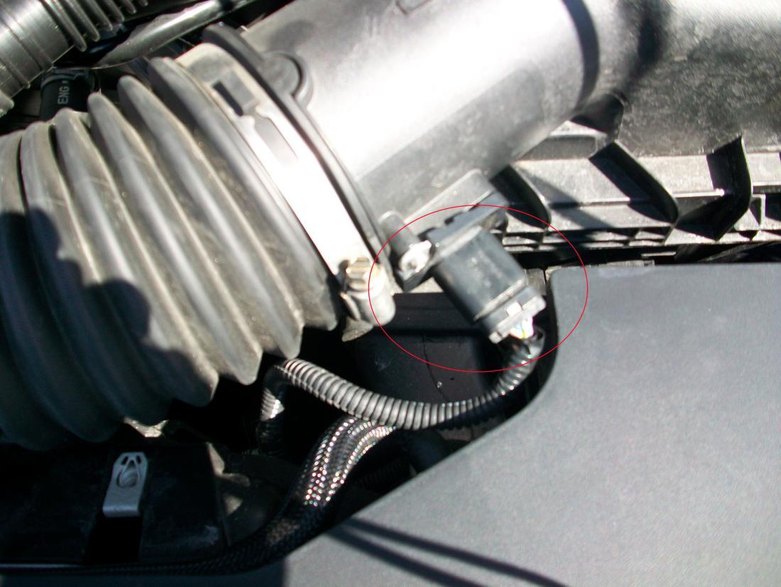
Figure 6
- Remove stock air filter housing.
- Remove the 10mm bolt from the air filter housing located between the driver’s side fender and air box.Fig. 6
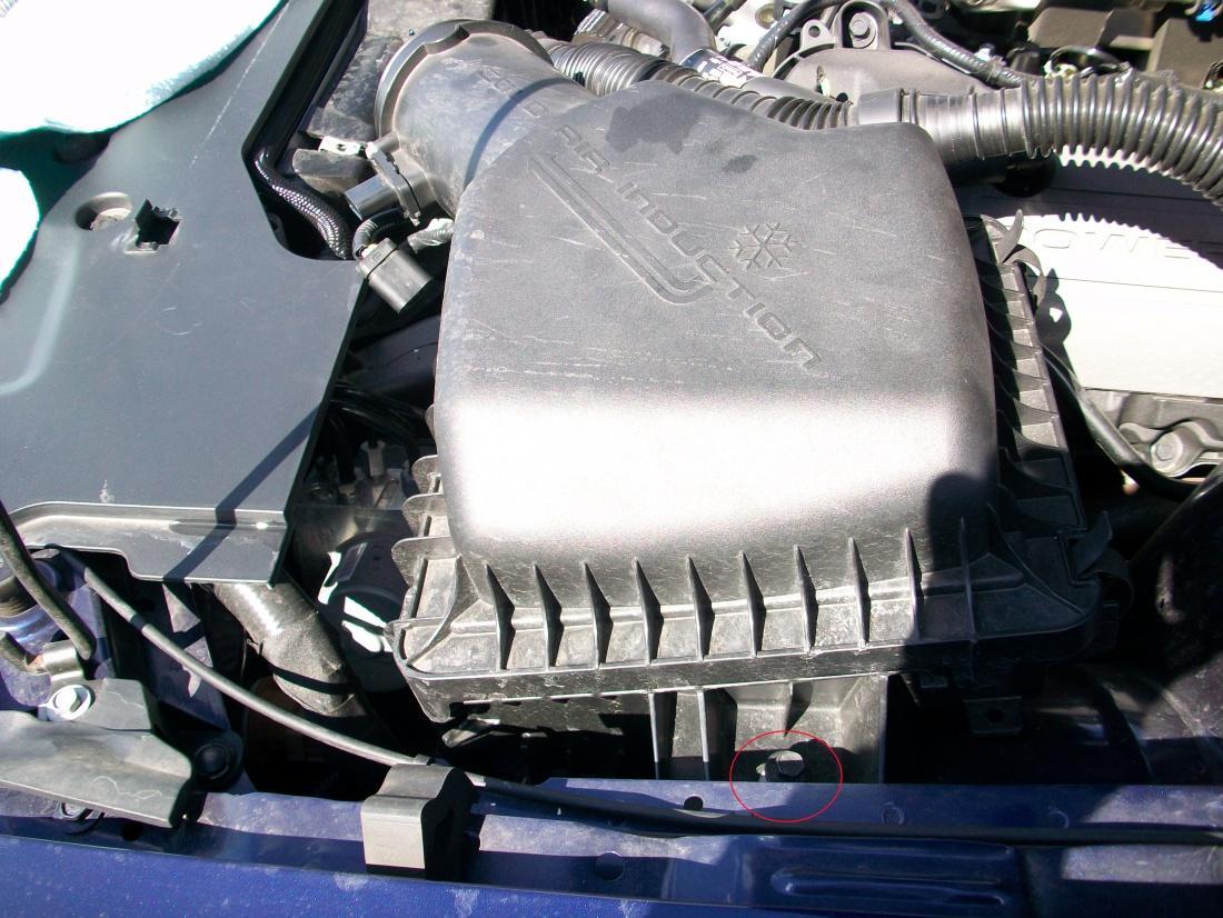
Figure 7
- Pull out any press through nylon fasteners connecting to air filter housing.
- Lift out the entire air filter assembly by lifting slightly upward and to the rear of the vehicle.
- After removal you will be able to see the incoming fresh air feed that enters from between the headlight assembly and the radiator support.Fig. 7
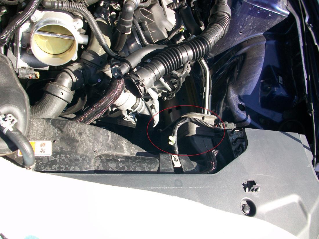
Figure 8
- Remove factory MAF sensor for factory intake assembly
- Using the supplied T-20 torx bit, remove the two screws that secure the factory air meter-sensing element from the stock air box assembly.Fig. 8
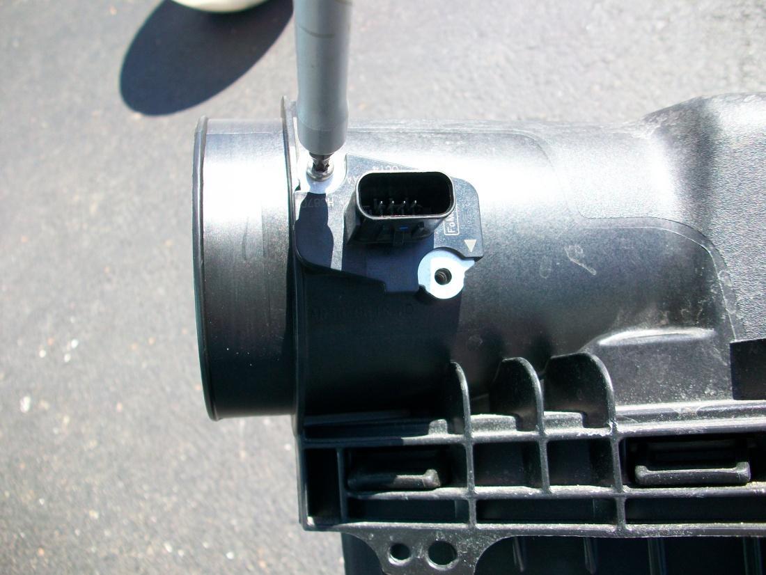
Figure 9
- Make sure the factory rubber seal comes out with the MAF sensor.
2. Install New C&L Intake Assembly
- Carefully lower the sensor in the new aluminum MAF housing from the kit.Fig. 9
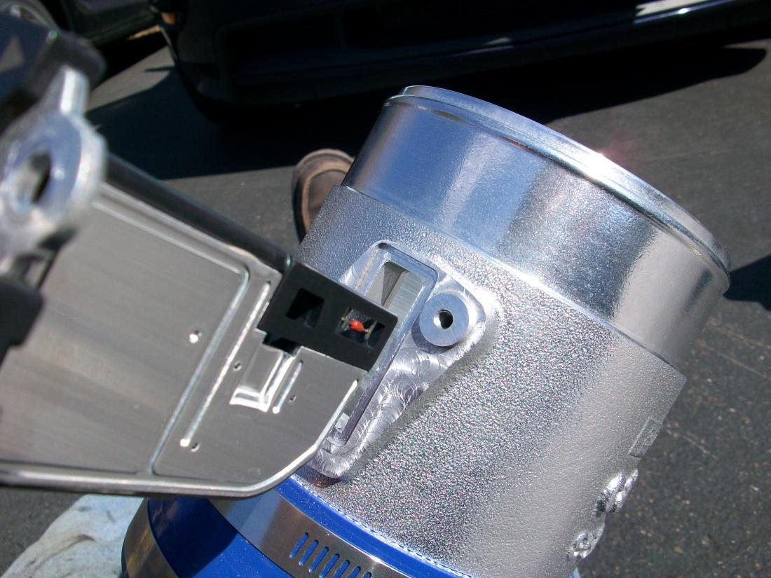
Figure 10
The sensor will only bolt up one way, with the ‘flow’ arrow pointing towards the engine inlet pipe.
Install new filter shroud.
- Lower the new shroud into the engine compartment with the lower ‘scoop’ portion of the shroud going down first, behind and under the rubber seal of the fresh air intake feed.Fig. 10
Figure 11
- Move the shroud as far forward as you can under the fresh air feed.
- Locate the 10mm bolt hole from the stock air filter assembly and line up the shroud mounting hole with this hole and reinstall factory 10mm bolt.Fig. 11
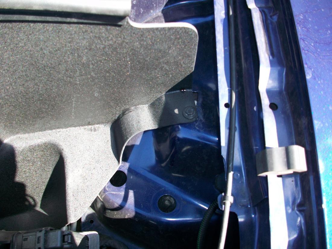
Figure 12
OPTIONAL – Drill a small diameter hole in the bottom of the rubber section of the fresh air feed in a location that lines up with the hole on the bottom of the new shroud and use the kit supplied bolt and nut to mount.
Air Filter Fittings
For Manual transmission – Use the nylon plug and insert and tighten into the hole between the valve cover tube and noise transmission tube.
For Automatic transmission – Use the barbed nipple fitting and insert and tighten into the hole between the valve cover tube and the noise transmission tube.
The fittings are tapered and will self seal by using a wrench.Fig. 12
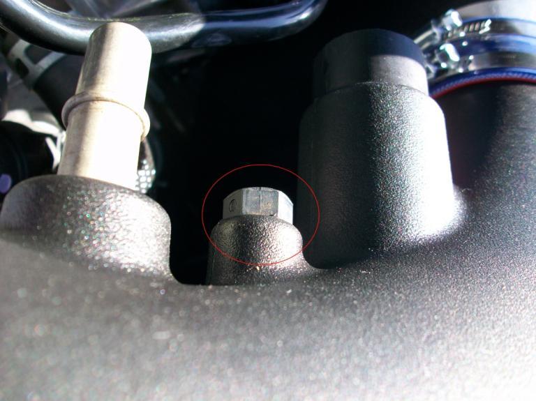
Figure 13
Install the new intake assembly
Lower assembly into the engine compartment and slide the silicone hose over the throttle body and tighten the clamp that goes over the throttle body flange.Fig. 13
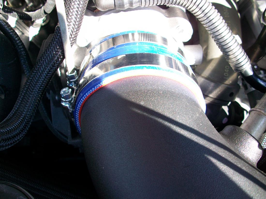
Figure 14
Connect the stock MAF sensor wiring to the MAF sensor mounted on the new air filter assembly.Fig. 14
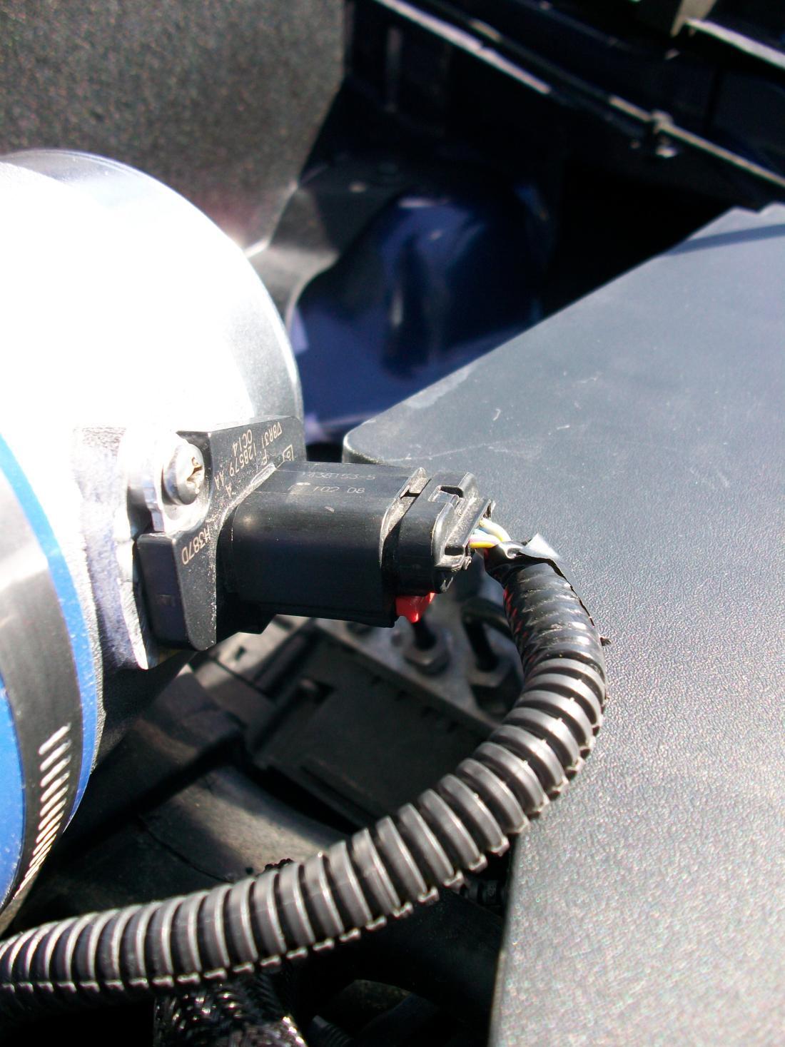
Figure 15
Slide the kit supplied filter over the neck of the new MAF body and orient the clamp so that you can tighten it with a screwdriver.Fig. 15 (Isn’t it massive!)
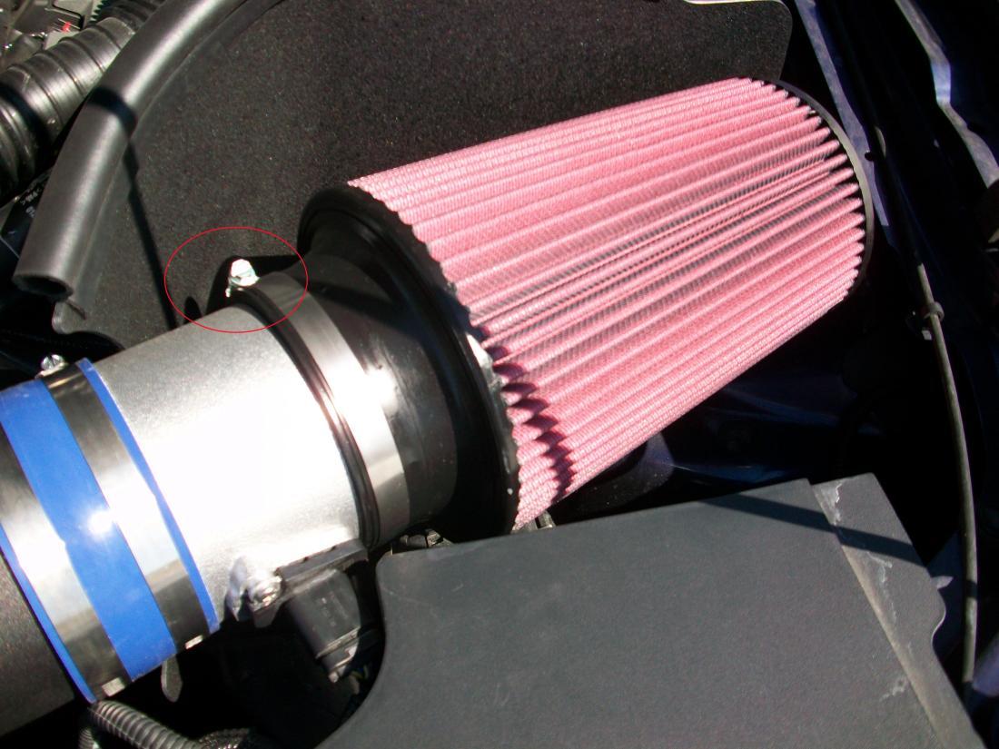
Figure 16
Reconnect the valve cover vent tube fitting to the new inlet tube. It should click into place.
Slide the noise transmission tube all the way over the new mount and release the spring clamp.
TRICK – Take two flat head screwdrivers and release the clamp by applying slight pressure in opposite directions.Fig. 16
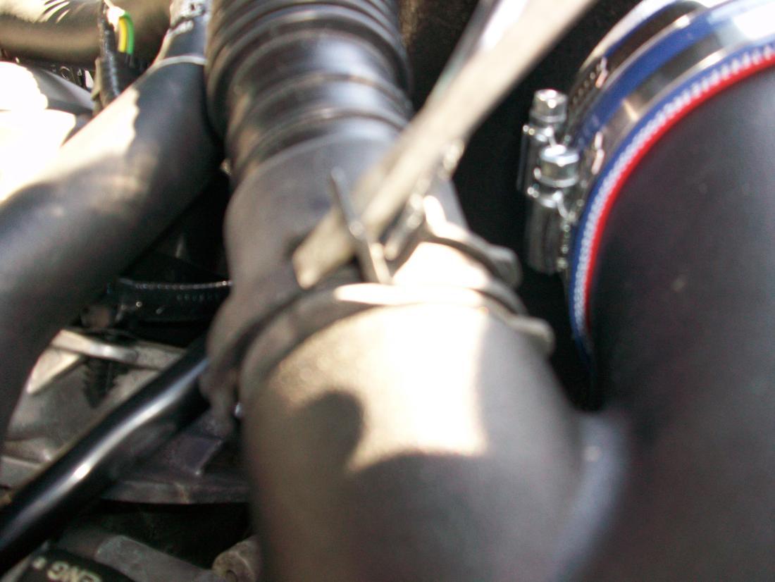
Figure 17
For automatic transmission equipped vehicles reuse the original molded rubber hose to reattached to new fitting.'
- Pull back the plastic conduit and cut the hose just aft of the factory nylon release fitting The exposed 3/8” tubing will then slide over the barded nipple fitting that you previously installed.
- Tighten all clamps once you are satisfied with the alignment of the entire assembly.
- Reinstall the factory engine cover and strut tower brace.
- Lineup the factory engine cover over the rubber mounts and ‘pop’ back on.
- Align strut tower brace over tower studs and mount using the factory 13mm nuts.Fig. 17
Enjoy!

