FREE 1 to 3-Day Delivery on Orders $149+ Details
How to Install a C&L Cold Air Intake on your 2011-2013 Mustang V6
Installation Time
1 hours
Tools Required
- flat blade screwdriver
- socket wrench with extension
- 8mm socket
- 10mm socket
- socket driver for the supplied T-20 torx bit.

Shop Parts in this Guide
Before installing this product, read these instructions carefully.
Note: This air intake assembly was developed to be installed without the need for a computer re-tune. The mass airflow signal is very close to that of the original air intake assembly, while increasing the airflow capacity from the stock level of 685 CFM to just under 900 CFM. This air intake may be used in conjunction with a “standard” performance tune programmed for whatever octane level fuel you choose to run. The installation of this system does not alter the air/fuel ratio under any driving conditions. Our testing revealed that when using standard 87 octane fuel the timing level was not consistent from run to run with maximum measured timing fluctuating from 15 to 17 degrees at wide open throttle. We recommend that you use “mid grade” 89 octane fuel at the minimum with factory stock tuning and premium fuel with any performance tuning. With the installation of this system and with the timing holding at the same level as stock, clear performance gains will be realized from 4,000 RPM all the way to redline. The sound of the vehicle will have a much deeper and throatier tone as compared to the stock air intake assembly.
Tools needed for installation: a flat blade screwdriver, socket wrench with extension, 8mm socket, 10mm socket, and a socket driver for the supplied T-20 torx bit.
**IMPORTANT NOTE: DO NOT USE THE SELF-TAPPING SCREWS IN OUR MAF HOUSING. We have provided new MAF sensor screws to replace the factory self-tapping screws. If you use the factory screws, you will ABSOLUTELY damage your new mass airflow housing, and we can not be held responsible.
1. Loosen the clamp that secures the stock inlet hose to the throttle body. You will notice a large diameter black nylon vacuum hose that runs from the valve cover to the stock inlet pipe, just to the right of the throttle body. Reach for the fitting that attaches this hose to the inlet pipe. There is a little tab that is holding the fitting in place over the boss on the inlet pipe. Move this tab over with your thumb or index finger and then pull the connector away from the inlet pipe towards the driver’s compartment. If you have an automatic equipped vehicle, there will be a smaller fitting to the right of the valve cover vent tube. You will remove it from the stock inlet tube by pulling it towards the rear of the vehicle and away from the barbed fitting that is holding it on the inlet tube.
2. Disconnect the MAF sensor located on the front of the air filter housing which has a wiring connector plugged into it. To disconnect, slide the red tab on the bottom of the connector towards the front of the vehicle. This will unlock the connector. Slide the connector off the MAF sensor by squeezing the tab on the underside of the connector and pulling it towards the front of the vehicle. Go to the end of the stock air filter assembly to your right, and you will see a 10mm bolt located between the driver’s side fender and the air box. Loosen and remove this bolt and set it aside for future use. You must now separate the mass airflow wiring harness from the factory air filter box assembly. There is a combination of both small tabs and “press through” nylon inserts that attach the harness to the front of the air filter box. Pull them away from the factory box assembly, so that the harness is no longer attached. At this point, the entire air inlet assembly can be taken out of the engine compartment. After removing the rubber inlet hose from the throttle body, move the air box assembly slightly upward and mostly towards the rear of the vehicle. This will release the rubber feet that isolate it from the body and slide the lower half of the air box from the incoming fresh air feed that enters in from between the headlight assembly and radiator support. The entire assembly will come out by lifting it up and out of the engine compartment.
3. Using the supplied T-20 torx bit, remove the two screws that secure the factory air meter-sensing element to the stock air box assembly. Carefully slide the sensor straight out of the housing, and the entire sensor cartridge will come out. Re-insert the factory self-tapping screws back into the factory housing for both safe keeping and to ensure that they are not used with our new upgrade MAF assembly. Using the new supplied screws, carefully lower the sensor into the new larger aluminum MAF housing provided in this kit. The sensor will only bolt up in one direction, with the “flow” arrow pointing towards the engine (inlet pipe) end of the unit, away from the filter end. Under the stock sensor, there is a rectangular shaped rubber seal that should come out with the sensor cartridge. Make sure that it transfers to the new housing and forms a positive seal. Attach the mass airflow housing to the larger end of the inlet tube using the 3.5” silicone hose coupler and #56 stainless steel hose clamps. Make sure the airflow arrow on the MAF sensor is pointing towards the inlet pipe and the beveled end of the MAF is facing the air filter. The sensor should be point towards you (and the front of the vehicle) while the “C&L” logo will be pointing “up” to your left. At this point, the silicone hose should completely cover the machined end of the MAF body. Make sure that the hose on the inlet pipe has been pushed
down far enough so that the MAF body presses solidly up against the inlet tube and there is no gap between them. Failure to do so will lengthen the overall assembly, and may effect air filter location and fitment. Not installing the silicone hose far enough over the inlet tube is the potential to deform the tube if too much clamping force is placed near the very outside edge of the tube itself from over-tightening the hose clamp.
4. Take the filter shroud and lower it into the engine compartment, with the lower “scoop” portion of the shroud going down first, behind and under the rubber seal of the “fresh air” intake feed. Move the shield as far forward as you can under the rubber flange of the fresh air feed, and then locate the bolt hole of the filter shroud with the original 10mm bolt hole that held the factory air filter box in place. Re-use the factory 10mm bolt to fasten the shield in place. An additional mounting point for the shroud assembly to attach to the underside of the factory fresh air feed has also been implemented. To attach this additional mounting support, you must drill a small diameter hole in the appropriate location in the bottom of the rubber (flange) section of the fresh air feed in a location that corresponds with the hole in the filter shroud. Make sure that the shroud is not too far forward when you locate where the hole will be drilled. You do not want the air filter to rub against the ABS lines. The supplied hardware (already installed on the lower portion of the shroud for reference) will secure the bottom of the filter shroud assembly to the lower section of the fresh air feed. Failure to secure this lower mounting point with the supplied hardware will result in the filter shroud not staying in place around the fresh air feed tube
5. There are two different fittings provided with the air intake assembly. The proper fitting for use on your vehicle application will depend on which transmission you have. Manual transmission vehicles will insert and tighten the supplied nylon plug to cover the threaded hole in the inlet tube. Automatic equipped vehicles will use the barbed nipple fitting to thread into the tapped hole. Using a wrench to install the correct fitting, you will notice that it gets tighter as the fitting goes further into the boss. Stop threading the fitting into the boss once the bottom of the wrenched fitting reaches the top of the boss in the inlet tube.
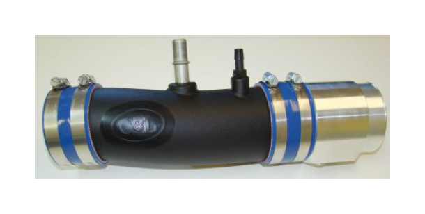
6. Slide the remaining 3” silicone hose over the smaller end of the inlet tube. As with the other hose, it will be a tight fit. Once the hose is over the end of the tube, there will be approximately 1” of hose sticking out of the “bottom” side of the tube and roughly 1.25” sticking out from the “top” end of the tube (which is the next to the “C&L” logo). Put the smaller clamps over this hose, but do not tighten them yet, as you will need to align the assembly on the vehicle before tightening everything. Check the supplied photo for reference of what the assembly SHOULD look like before you install it on the vehicle. Note the clamp orientation.
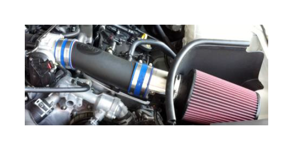
7. Lower the inlet assembly into the engine compartment by first slipping the end of the MAF housing through the round opening in the air filter shroud and then sliding the silicone hose all the way over the throttle body. Tighten the hose clamp that goes over the throttle body flange while leaving the clamp that goes over the inlet tube slightly “loose”. You may now adjust the location of the inlet tube and MAF assembly in the engine compartment for proper fitment. Note that the “C&L” logo will be pointing almost straight up and that when the (rotational) orientation of the tube is correct, the angle of the large boss in the inlet tube will be at basically the same angle as the molded nylon tube that slides over the fitting. If the air meter housing is properly located through the opening in the filter shroud, there should be an equal distance around the end of the MAF housing where the neck of the air filter slides over the end of it. Slide the supplied filter over the neck of the new MAF body. Orient the clamp so that you can tighten it with a screwdriver or socket wrench without the shroud getting in the way. If there is any question about fitment, you may adjust the orientation of the entire assembly prior to fully tightening the hose clamp that goes over the throttle body end of the inlet pipe. Re-connect the valve cover vent tube fitting on to the new inlet tube, making sure that the locking tab holds the fitting in place and that the fitting on the inlet tube is at the same basic angle as the rigid nylon valve cover vent tube. If you have an automatic equipped vehicle, you will need to re-insert the 3/8” rubber hose over the barbed nipple fitting of the new inlet pipe. Once you are satisfied with the fitment for the entire assembly, re-connect the wiring harness to the MAF sensor and tighten all hose clamps in the system. When installed properly, the end of the mass airflow housing and air filter neck will pass evenly through the round cut-out in the air filter shroud.
Now that the assembly is in place, it is time to re-check all connections to ensure proper installation. If everything has been connected properly and there are no air leaks, you are ready to run your vehicle.