 FREE 1 to 3-Day Delivery on Orders $149+ Details
How to Install a Ford Racing Cobra Jet Intake Manifold on your 2011-2014 Mustang GT
Please visit www.fordracingparts.com for the most current instruction information
! ! ! PLEASE READ ALL OF THE FOLLOWING INSTRUCTIONS CAREFULLY PRIOR TO INSTALLATION. AT ANY TIME YOU DO NOT UNDERSTAND THE INSTRUCTIONS, PLEASE CALL THE FORD RACING TECHLINE AT 1-800-367-3788 ! ! !
! ! ! WARNING – CALIBRATION IS REQUIRED! DO NOT DRIVE UNTIL CALIBRATION IS COMPLETE ! ! !
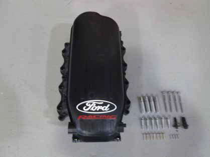
INTAKE MANIFOLD KIT:
Quantity Part Name
1 Intake Manifold
4 Aluminum Fuel Rail Spacer
6 M6 x 45mm Captive Bolt
4 M6 x 100mm Bolt
7 Self Tapping Screw x 25mm
4 Self Tapping Screw x 15mm
1 Driver Side Fitting
1 Passenger Side Fitting
1 Jumper harness
__________________________________________________________
Mustang GT applications require BOSS® 302 INTAKE MANIFOLD INSTALL KIT M-9444-M50B, not included.
CR3Z-9G297-A Fuel Vapor Hose
CR3Z-9G290-B Fuel Vapor Fuse Bracket and fasteners
CR3Z-9J280-A Fuel Line
Air Inlet Tube assembly – throttle body to air box. (inlet tube is not used)
Other parts required for installation, not included:
M-9926-C65 Throttle body
M-9603-M50CJ Cold air intake (available 3rd quarter 2013)
INSTALLATION INSTRUCTIONS:
FUEL SYSTEM PRESSURE RELEASE:
WARNING: Do not smoke, carry lighted tobacco or have an open flame of any type when working on or near any fuel-related component. Highly flammable mixtures are always present and may be ignited. Failure to follow these instructions may result in serious personal injury.
WARNING: Do not carry personal electronic devices such as cell phones, pagers or audio equipment of any type when working on or near any fuel-related component. Highly flammable mixtures are always present and may be ignited. Failure to follow these instructions may result in serious personal injury.
WARNING: Before working on or disconnecting any of the fuel tubes or fuel system components, relieve the fuel system pressure to prevent accidental spraying of fuel. Fuel in the fuel system remains under high pressure, even when the engine is not running. Failure to follow this instruction may result in serious personal injury.
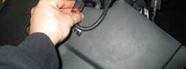
NOTE: The Fuel Pump Driver Module (FPDM) is located in the spare tire stowage compartment. Disconnect the FPDM electrical connector(s).
STEP 1: Start the engine and allow it to idle until it stalls.
STEP 2: After the engine stalls, crank the engine for approximately 10 seconds to make sure the fuel injection supply manifold pressure has been released.
STEP 3: Turn the ignition switch to the OFF position.
STEP 4: Disconnect battery.
INTAKE PREPARATION:
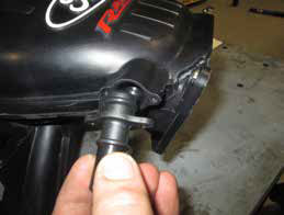
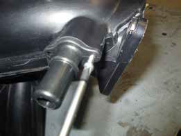
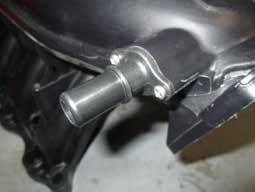
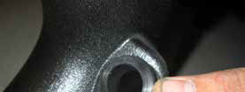
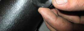
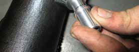
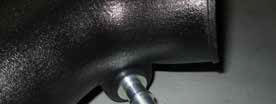
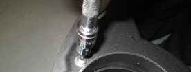
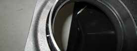
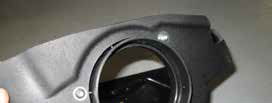
STEP 5: Lubricate o-ring and insert driver side fitting into intake manifold. Install (2) self tapping x 15mm screws and tighten.

STEP 6: Lubricate o-ring and insert passenger side fitting into intake manifold. Install (2) self tapping x 15mm screws and tighten.
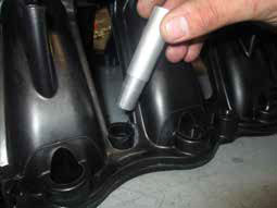
STEP 7: Install the (4) aluminum fuel rail spacers into manifold by gently pushing into the provided locations.
NOTE: For Mustang GT intake removal, go to pages 11-19. For BOSS 302 continue with STEP 8 below.
STEP 8: Unplug the mass airflow sensor by releasing the safety clip and unclipping the connector.
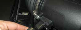
STEP 9: Remove intake side tube by depressing the hose clamp. Remove the tube.
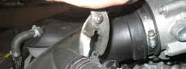
STEP 10: Remove breather hose by depressing safety clip and sliding the tube off of the intake tube.
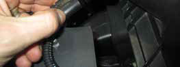
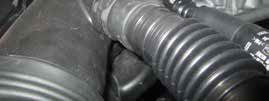
STEP 11: Loosen both intake tube hose clamps at the throttle body and air box assembly.
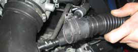
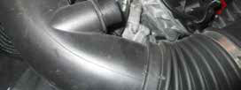
STEP 12: Gently slide the intake tube off of the throttle body then off of the air box. Remove from car.
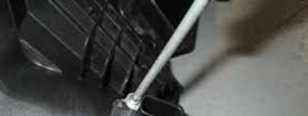
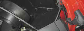
STEP 13: Remove the air box retaining bolt. Remove air box from car.
STEP 14: Remove both foam isolators by removing (2) nuts per side. Remove from car.
STEP 15: Unplug the throttle body by releasing the safety clip and unclipping the connector.
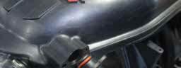
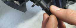
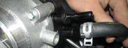
STEP 16: Remove both driver / passenger intake hoses by depressing safety clip and sliding the tube off of the intake fittings.
STEP 17: Remove the connector on the driver side rear of intake manifold by gently depressing the clip and removing.
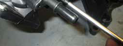
STEP 18: Slide the sensor and rubber isolator off of the intake manifold retaining bracket.
STEP 19: Remove fuel line feed by releasing the safety clip and sliding line off of the fuel rail. Be sure to cover the area with a towel as the line will release fuel.
STEP 20: Remove both driver / passenger side water bypass hose retention plates by removing (2) bolts per side. Remove from car.
STEP 21: Remove both driver / passenger side fuel rail isolator foam from car.
STEP 22: Depress hose clamp and remove brake booster tube from intake manifold.
STEP 23: Disconnect (8) injector connectors by depressing the locking clip and removing from injector.
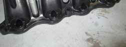
STEP 24: Blow off any loose debris from intake / cylinder head area. Remove (10) intake retaining bolts around the base of the intake manifold.
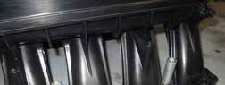
STEP 25: Remove intake manifold from car by lifting upwards. Place tape over the cylinder heads exposed openings to prevent foreign objects from entering the engine.
STEP 26: Remove fuel rail and injector assembly from the original intake by gently pulling upwards. Ensure the injector o-rings are intact and not damaged once removed. Clean any loose debris from injectors.
Mustang GT Intake Removal, STEPS 1-13 on pages 11-19. BOSS 302 go to STEP 27 on page 19.
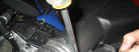
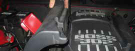
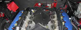
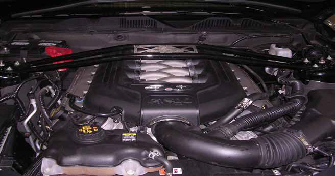
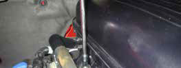
STEP 1: Remove strut tower brace. (Note: Original strut tower brace will not fit with the Boss 302 intake)
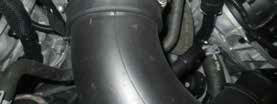
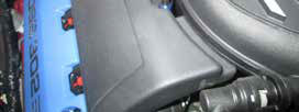
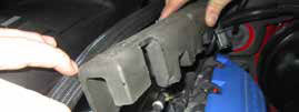
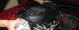
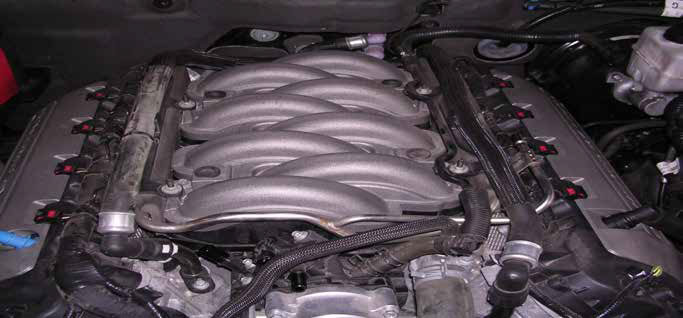
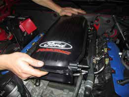
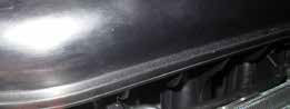
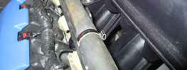
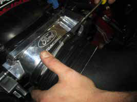
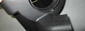
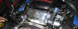
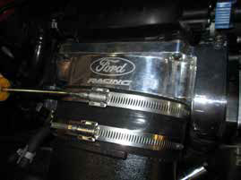
STEP 2: Remove intake cover from intake.
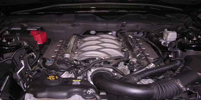
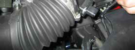
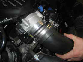
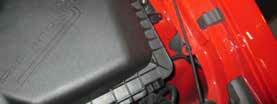
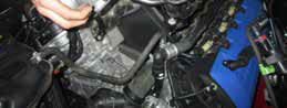
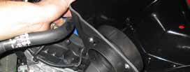
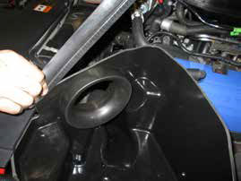
STEP 3: Remove air cleaner box lid and tube assembly.
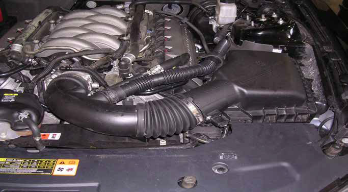
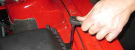
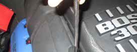
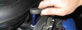
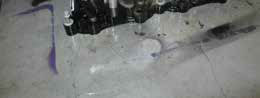
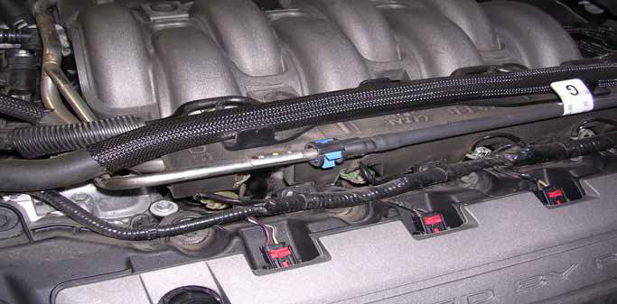
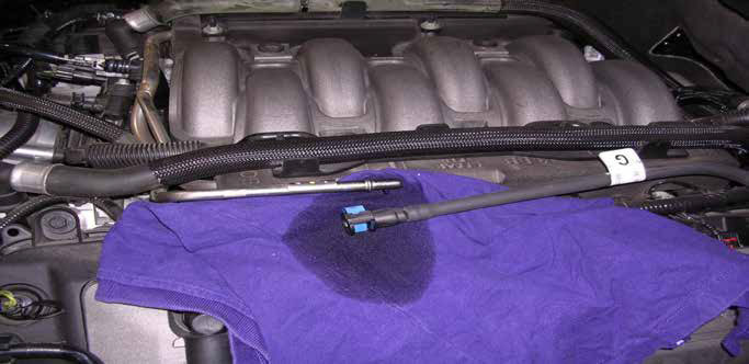
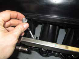
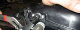
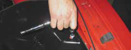
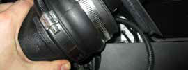
STEP 4: Fuel Pressure must be released before performing the following step! Disconnect the fuel line by first removing the safety clip. Put on safety glasses.
WARNING: Fuel will spill out when you disconnect the line so it is best to place a rag below the connection to absorb the fuel that spills.
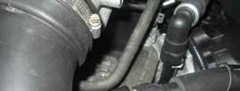
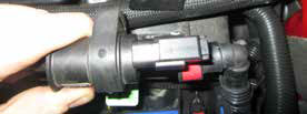
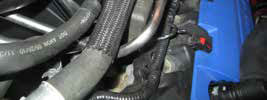
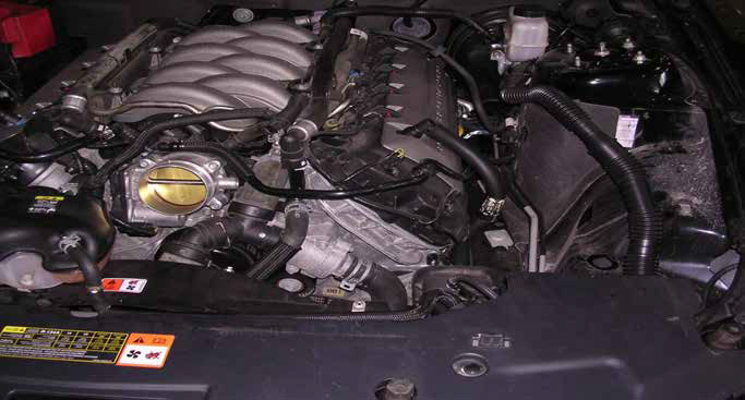
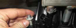
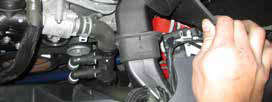
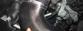
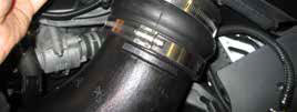
STEP 5: Remove PCV tube from intake.
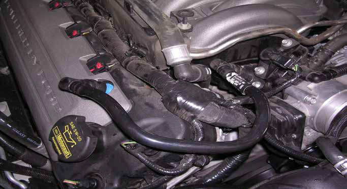
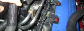
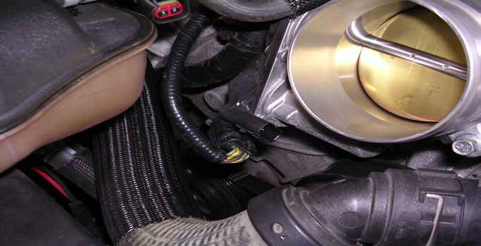
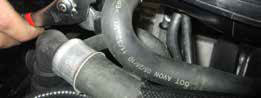
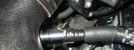
STEP 6: Remove vapor line and disconnect electrical connector from purge valve and throttle body connector.
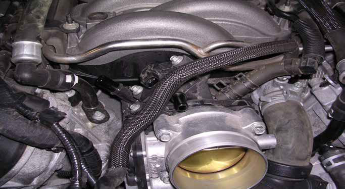
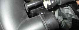
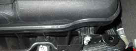
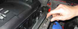
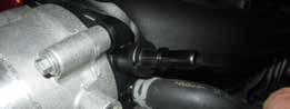
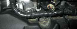
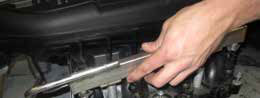
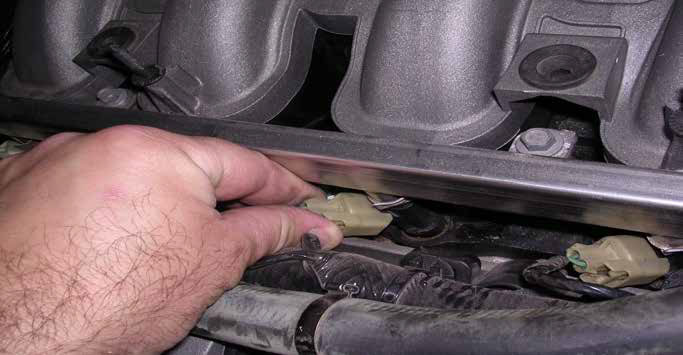
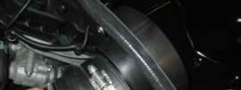
STEP 7: Disconnect vacuum line from intake to brake booster.
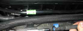
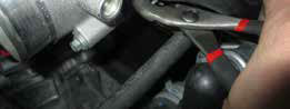
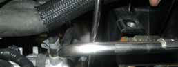
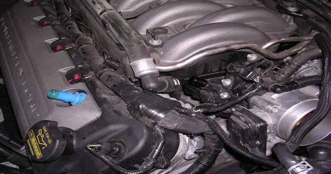
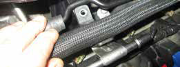
STEP 8: Remove nuts holding down heater hose and vacuum line rails. Then remove vacuum line.
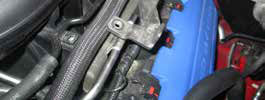
STEP 9: Move heater hose off to the side and remove LH and RH fuel rail insulators.
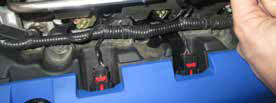
STEP 10: Unplug 8 injectors by pushing in clip and pulling straight out.
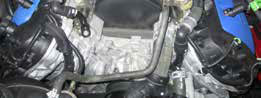
STEP 11: Confirm base of intake is clean of debris.
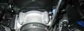
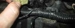
STEP 12: Remove wire harness clips from rear of intake (4) places.
STEP 13: Remove (4) fuel rail bolts and loosen (6) intake bolts, Remove intake and place on work bench.
Mustang GT and BOSS 302 Intake Install:
STEP 27: BOSS 302, remove driver side rearward bracket from the original intake manifold.
Mustang GT Applications:
Install the Evaporative Emission (EVAP) canister purge valve bracket. (From kit part
number M-9444-M50B)
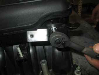
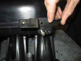
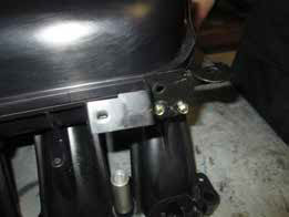
STEP 28: Install driver side rearward bracket onto the new intake manifold using (2) of the provided self tapping x 25mm screws and tighten.
STEP 29: Lubricate injector o-rings and install the fuel rail and injector assembly into the new intake. Gently push down on all (8) injectors until seated properly.
STEP 30: Install the (4) M6 x 100mm bolts through the fuel rail and into the previously install aluminum fuel rail spacers. Install (6) M6 x 45mm captive bolts into the remaining locations on the intake manifold mounting surface.
STEP 31: Remove tape from cylinder heads ensuring the mating surface is clean of debris. Verify all (8) intake runner gaskets and (1) throttle body gasket is in place. Install the newly assembled intake manifold onto the cylinder heads and loosely start the (10) bolts.
STEP 32: Tighten the 6 intake manifold bolts in the sequence shown in 2 stages.
Stage 1: Tighten to 10 Nm (89 lb-in).
Stage 2: Tighten an additional 45 degrees.
STEP 33: Tighten the 4 fuel rail bolts in the sequence shown in 2 stages.
Stage 1: Tighten to 10 Nm (89 lb-in).
Stage 2: Tighten an additional 90 degrees.
STEP 34: Reconnect the (8) injector harness connectors to the injectors.
STEP 35: Reconnect the brake booster hose to the intake manifold and release the hose clamp.
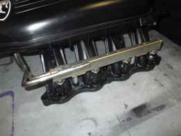
STEP 36: Install the water bypass hose retention plate on both sides of intake using (2) self tapping x 25mm screws per side and tighten.
MUSTANG GT Applications Only:
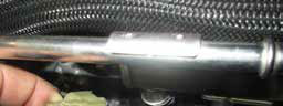
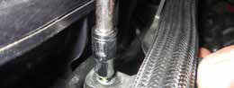
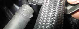
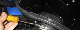
STEP 1: Remove original fuel line and vapor line by disconnecting lines at rear base of left hand wheel well.
STEP 2: Remove new lines from installation kit part number M-9444-M50B and connect line at rear base of left hand wheel well.
NOTE: Wiring for purge valve will have to be extended approximately 40 inches of 18 awg wire, cut and splice wire, solder and weather tight shrink tube.
STEP 37: Install sensor onto intake manifold retaining bracket by sliding into position. Reconnect sensor.

STEP 38: Connect fuel line by sliding onto fuel rail until fully engaged, ensure safety clip is in the locked position.
STEP 39: Connect both driver and passenger hoses onto intake ensuring the retaining clips are in the locked position once installed.
STEP 40: Install throttle body M-9926-CJ65 (not included) and tighten bolts.
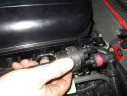
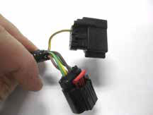
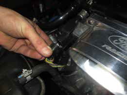
STEP 41: Replace the factory connector with the provided mating connector. Please review the following information before proceeding to STEP 42.
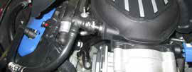
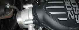
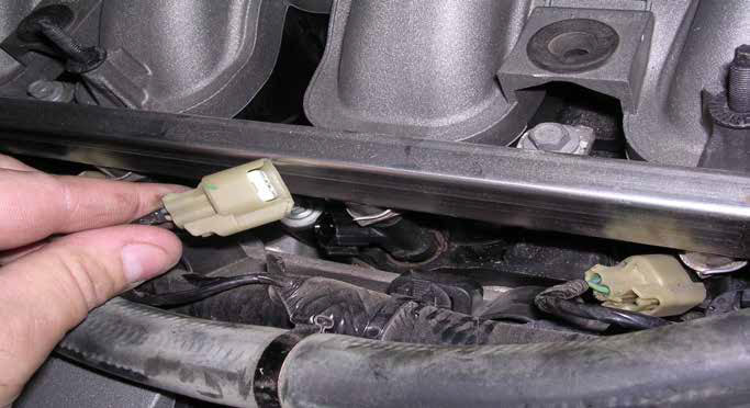
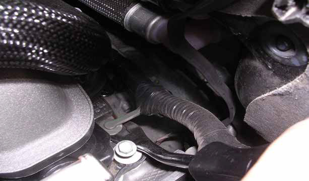
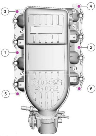
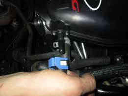
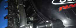
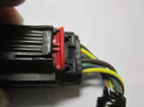
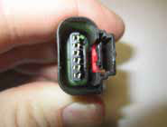
The factory harness connector will need to be replaced by using the new mating connector provided with the throttle body jumper harness. The location of the connector to be replaced is identified in Figure 1, referred to as C1449 (in RED).
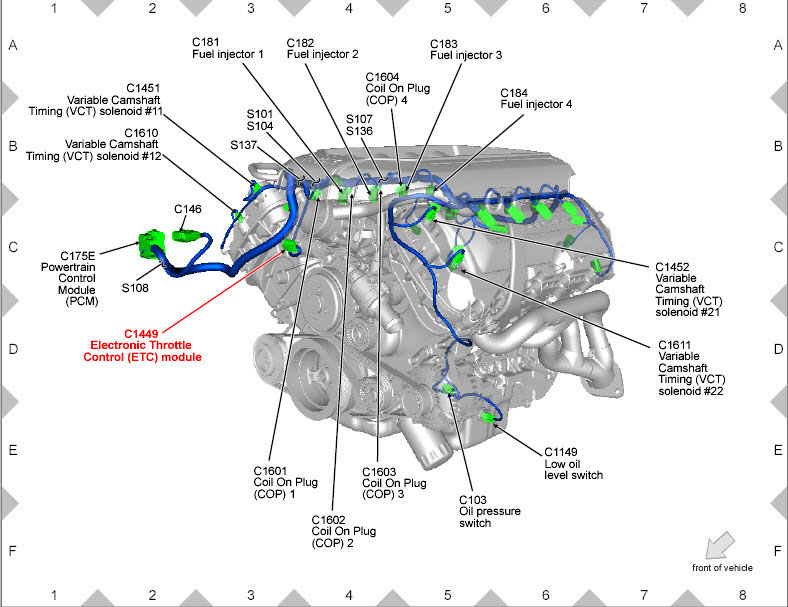
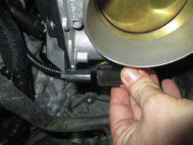
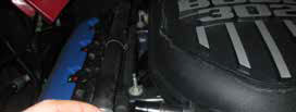
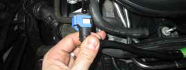
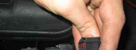
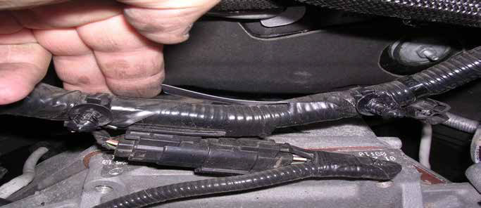
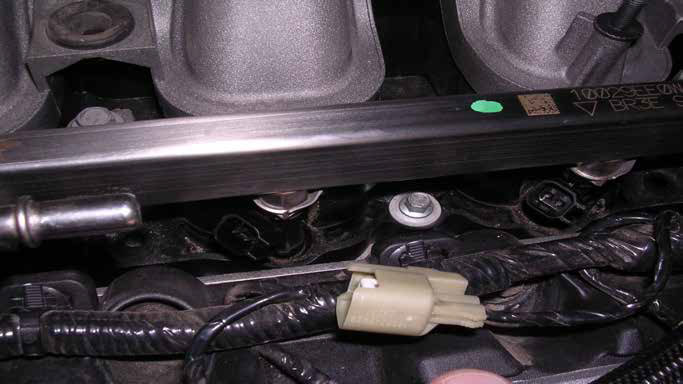
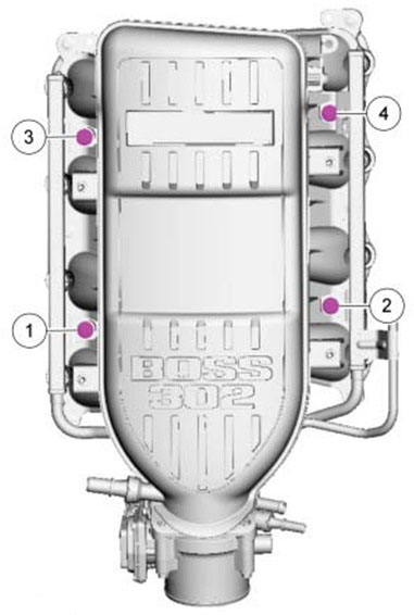
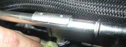
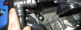
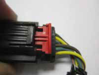
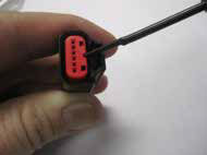
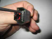
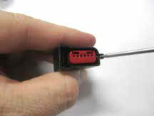
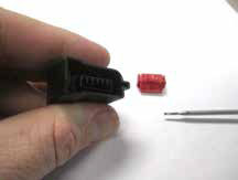
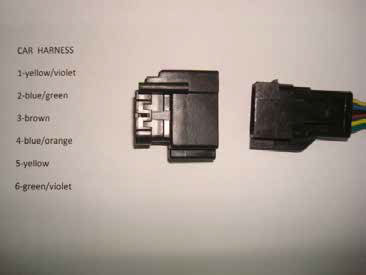
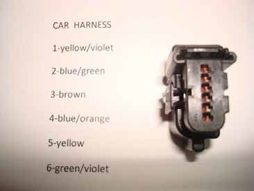
Identify the correct connector using Figure 2 below. This connector will be replaced with the connector shown in Figure 3.
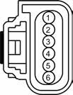
Figure 2
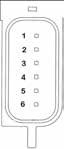
Figure 3
Replacing the Factory Harness Connector:
The use of a pin extraction tool is recommended for this process. If you do not have a pin extraction tool, you may use a very thin screwdriver such as those used for repairing eyeglass frames.
TO INSURE THIS PROCEDURE IS DONE PROPERLY, IT IS HIGHLY RECOMMENDED TO SWAP ONLY ONE PIN AT A TIME!!
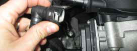
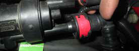
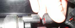
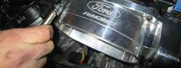
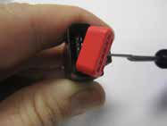
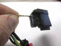
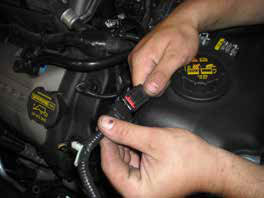
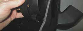
STEP 41A: Unplug the factory connector from the throttle body. The red locking tab on the factory harness connector must be released to do this.
LOCKED
UNLOCKED
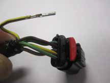
STEP 41B: Gently pry the red retaining lock from the factory connector to reveal the female terminals.
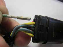
STEP 41C: Starting with Pin 1, carefully pry back the plastic retaining tab (which holds the female terminal into the connector housing) while gently pulling on the wire from behind until the terminal has been released.
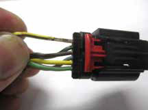
STEP 41D: Completely remove the wire and terminal from the factory connector.
STEP 41E: Prepare the NEW replacement connector for terminal insertion by removing the red retaining lock from the connector. Like the previous connector, this lock can also be removed by gently prying out.
STEP 41F: Insert the terminal (from STEP 41D) into the NEW replacement connector noting the orientation of the terminal. A locating tab on the terminal will allow the terminal to insert in only one direction. DO NOT FORCE!
NOTE: When the terminal seats properly, you should hear a light clicking sound. Gently pull on the wire to insure that it has seated properly into the NEW connector housing.
STEP 41G: Return to STEP 41C, and follow the same sequence for Pin 2 through Pin 6. Once all six terminals have been moved, replace the red locking tab (previously referred to in STEP 41E).
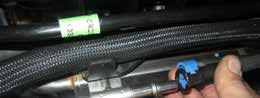
STEP 41H: After the NEW connector has been attached to the engine harness, connect the new jumper harness and route to the new throttle body’s Throttle Position Sensor (TPS) and Electronic Throttle Control (ETC) motor. There is a fir tree clip that will allow the harness to be securely fastened to the cylinder head.
When properly assembled, the factory wire colors should match the connector as follows:
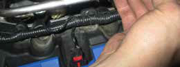
STEP 42: Clip the provided jumper harness into the newly installed mating connector.
STEP 43: Clip the remaining (2) connectors on the jumper harness to the throttle body.
STEP 44: Install intake tube and tighten hose clamps. (M-9603-M50CJ CJ Cold air intake not included, available 3rd quarter 2013)
STEP 45: Remove (2) screws from the mass airflow meter and remove from the production intake tube.
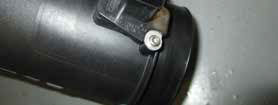
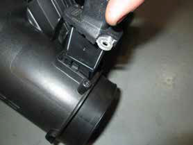
STEP 46: Install the mass airflow meter into the new intake tube ensuring proper orientation. Install the (2) provided MAF screws and tighten.

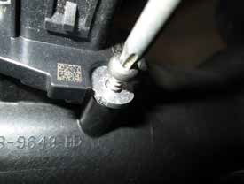
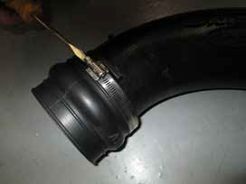
STEP 47: Install the provided grommet into the provision on the intake tube. Install the aluminum fitting into the grommet.


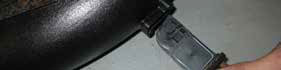
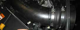
STEP 48: Install the silicone tube onto the intake tube with (1) large hose clamp and tighten.
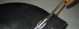
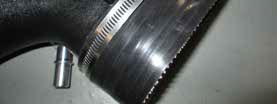
STEP 49: Install the urethane hump hose onto the intake tube with (1) medium hose clamp and tighten.
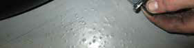
STEP 50: Install the filter adapter into the air box using the (3) provided button head bolts and tighten.
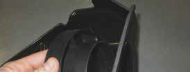
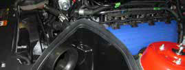
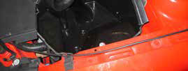
STEP 51: Install the new air box assembly by sliding it into the OEM air scoop. Reinstall the air box retaining bolt removed in STEP 13 on page 6.
STEP 52: Install the provided weather strip around the perimeter of the newly installed air box.
STEP 53: Install the intake tube onto the throttle body with (1) large hose clamp then over the air filter adapter with (1) medium hose clamp. Tighten both clamps.
STEP 54: Install the breather hose onto the intake tube aluminum fitting.
STEP 55: Connect the mass air flow meter connector ensuring the safety clip is in the locked position.
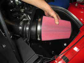
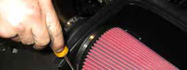
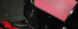
STEP 56: Install the new air filter onto the air filter adapter and tighten.
STEP 57: Reconnect the battery.


STEP 58: Start vehicle and check for fuel and vacuum leaks.
! ! ! WARNING – CALIBRATION IS REQUIRED. DO NOT DRIVE UNTIL CALIBRATION IS COMPLETE ! ! !

