 FREE 1 to 3-Day Delivery on Orders $149+ Details
How to install a Ford Racing 306ci 340HP Crate Engine on your Mustang
Installation
ENGINE INSTALLATION AND TUNING TIPS:
Performance engine durability is dependent on several supporting systems including the cooling system, fuel delivery system, ignition system, and oiling system. If the support systems are not adequate, poor engine performance and possible engine failure could result.
OILING SYSTEM CONSIDERATIONS/COMMON PROBLEMS
Priming the oiling system before starting a new engine is crucial to engine life. This is important on initial start-up of a new engine and if a used engine has not been run for extended periods of time.
Does the oil pan have adequate capacity? Most performance vehicles require a 7-qt minimum capacity. All engines will benefit from increased oil pan capacity.
Does the oil pan have proper oil control baffling for the vehicle’s braking, acceleration, and cornering capabilities?
Road Race cars need oil control in four directions: braking, acceleration, LH cornering and RH cornering. Drag race cars need oil control in two directions, braking and acceleration. Baffles must be designed to keep oil over the pickup screen at all times.
Is the pickup screen the proper distance from the bottom of the oil pan? If the oil pickup screen is too close to the bottom of the oil pan, it can cause cavitation. If it is too far away, it will cause the pump to draw air and minimize lubrication capacity. The pickup screen should be located .250" to .375" from the bottom of the pan.
Does the design of the screen on the pickup tube create restrictions? We have seen some pickup tube screen designs that restrict oil flow as much as 75%. Wire mesh is good. Perforated metal is usually restrictive. Measure the wire size and calculate the flow area. Most aftermarket screens have less flow area than stock screens.
If using a remote oil filter mount or oil cooler, make sure that all of the components are large enough to eliminate any restrictions to oil flow. Many Cobra replica kit cars use components that are too restrictive.
- Undersized oil lines commonly restrict oil flow.
- The more bends/turns in an oiling system, the more restrictions that are created.
- Poorly designed remote filter mounts and adapters can create restrictions.
- Be sure that the oil cooler flows enough oil to meet the engine's requirements.
- Never reuse a used oil cooler. Debris gets trapped and cannot be cleaned out.
- Poorly designed oil filters can cause a restriction.
- Many oil systems only flow one way. Connecting the remote oil filter or oil cooler lines backwards can cause engine damage/failure.
IGNITION SYSTEM CONSIDERATIONS/COMMON PROBLEMS
The ignition system must deliver a properly timed spark. There are a lot of factors that determine when the spark should be delivered. The most common factors include: compression ratio, fuel quality, fuel octane rating, combustion chamber design, engine operating temperature, power adders such as NOS or supercharger, inlet air temp, altitude, and load.
- Avoid too much or too little timing for your engine combination.
- Avoid hooking up the vacuum advance to intake manifold vacuum instead of ported vacuum.
- Avoid inductive crossfire created by improper plug wire routing. Separate plug wires on cylinders that fire in sequence.
- Improper timing can damage pistons, rod bearings, head gaskets, and many other engine parts.
- Typical total mechanical advance timing at 4000 rpm for Ford Racing Performance Parts crate engines: 5.0L - 36° to 38° With factory EFI, 14 to 16 degrees initial.
FUEL DELIVERY CONSIDERATIONS
Size of fuel pump, size of fuel line, fuel pump placement, fuel filter placement, fuel filter size, injector size, fuel rail size, fuel pressure, jet size, and baffling in the fuel tank.
Does the fuel system maintain full pressure at peak engine horsepower in high gear? Altitude, air temperature, and fuel characteristics including quality, specific gravity, and octane rating, will affect your jetting requirements. Engine efficiency and Brake Specific Fuel Consumption (BSFC) also have an effect. Here are some examples of a Holley 750 CFM 4V.
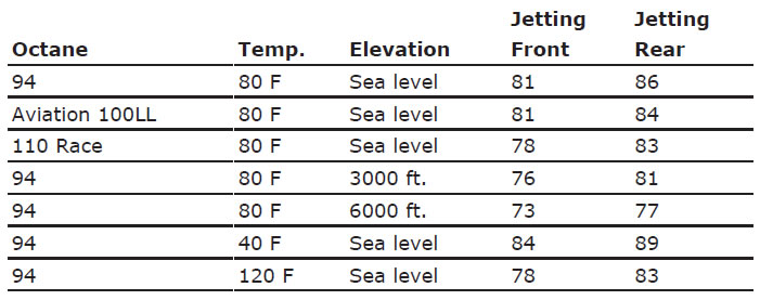
As you can see by these examples, jet requirements can vary a lot depending on fuel, altitude, and temperature. Oxygenated fuels are available in some states and can dramatically affect your jetting requirements. Make sure you get your jetting correct.
Aviation fuel is lighter and will require richening an engine in relationship to its requirement with "pump gas." We have found in the dyno testing of our crate engines that 1 point richer on air/fuel ratio equals only a few percent less power. Running an engine as lean as possible produces the best power but also increases combustion temperatures and the chances of engine damage.
COMMON PROBLEMS WITH FUEL DELIVERY SYSTEMS
Do not mount an EFI electric fuel pump so it has to draw fuel from the tank. This creates a negative pressure in the fuel line allowing the fuel to boil at a lower temperature.
The pump must be mounted in the tank or in a location so that it is gravity fed. If the fuel rail is too small and you have large injectors, this can create a pulse in the fuel rail allowing fuel starvation on some cylinders.
Fuel should be pushed through the fuel filter. Pulling fuel through a filter can cause cavitation. If a filter is to be used on the inlet of a rail-mounted fuel pump, a filter rating of 160 microns MINIMUM should be used. It takes approximately ½ lb of gasoline to support 1 hp. This is commonly referred to as a .5 BSFC. You should always err in the safe direction of larger when sizing your injectors and fuel pump.
COOLING SYSTEM CONSIDERATIONS/COMMON PROBLEMS
Higher horsepower requires more cooling capacity.
When the fill point of the cooling system is not the highest point, air pockets are created. The air pockets then create hot spots, and the hot spots promote improper combustion, which can cause engine failure. Improper pulley size makes the fan and water pump turn too slow or too fast. Production water pumps are normally run at 20% over engine speed and do not perform well over 5000 engine rpm. Underdrive pulleys generally reduce water pump speed to 85% of engine rpm and may not provide enough water flow to cool the engine. The radiator must have enough area to dissipate the heat being generated by the engine. If the fan size is too small, it will not move enough air across the radiator so it can properly dissipate the heat being generated. Fan shrouds increase the effectiveness of the fan significantly. Radiator location can affect airflow through the radiator at different vehicle speeds.
FLYWHEEL, CONVERTER, AND TRANSMISSION PROBLEMS
Installing the wrong flywheel for the balance factor of the engine will cause vibration and eventually damage the engine.
Wrong length input shaft or "stack up height" can force the crank forward and damage the engine thrust bearing.
Improperly installing the torque converter can force the crank forward damaging the engine thrust bearing. This is most commonly caused from not locating the torque converter drain plug properly in the flexplate. If the torque converter balloons, it can force the crank forward, damaging the engine thrust bearing and the transmission. Most high-performance torque converters have anti-ballooning features. Damage to the thrust bearing can happen in seconds!
MISCELLANEOUS PROBLEMS THAT CAN DAMAGE AN ENGINE
Nuts, bolts, washers, or foreign materials dropped down the intake. We have seen this more than once. Reusing an intake off an engine that had broken parts in a cylinder. The parts can get bounced up into the intake manifold, carburetor, or air cleaner (pieces of piston or piston rings, etc.). When you put your used intake on your new engine and start it, the pieces are drawn in and damage your engine.
Bead blasting an EFI intake. You will NEVER get all the blasting media out. When the engine is started, it draws the blasting media into the cylinders, destroying the engine. Not properly torquing fasteners when installing new parts to your engine. Over-torquing of the intake manifold bolts to cylinder head on 302 and 351W engines can cause head gasket sealing problems. Intake bolts must have 5/8” of thread engagement.
Distributor gears installed at the incorrect height and gears made of the wrong material. We have seen this with many remanufactured distributors as well as popular aftermarket manufacturers of distributor assemblies. Use cast iron gears for cast iron flat tappet cams, and steel gears for steel hydraulic roller cams. The M-6007-X302 uses a steel camshaft.
ENGINE OIL RECOMMENDATIONS
Hydraulic roller cam-equipped engines use 10W30 or 10W40. OIL CAPACITY M-6007-X302, 5 quarts with M-6731-FL1A oil filter or equivalent.
PRIMING
Initial priming should be done before installing the engine into the vehicle. Transmission should not be installed. If there are any oiling system problems, it is easier to fix them with the engine out of the car. The engine should be primed once more after installation before starting the engine. This is very important if hooking up a remote filter and/or oil cooler.
IMPORTANT: For engines equipped with flat tappet cams, if the engine has set for a long period of time, priming alone may not provide enough lubrication. Removal of lifters and reapplying cam lube to the lobes and lifters is necessary. For hydraulic roller cams use engine oil.
DO NOT PRIME BY CRANKING ENGINE! Check oil level after priming engine and before starting.
STEP 1: Use appropriate priming tool or ¼" drive, ¼” deep-well socket with extension for 302.
STEP 2: Install mechanical oil pressure gauge.
STEP 3: Remove valve covers.
STEP 4: Rotate priming tool counterclockwise using an electric drill.
STEP 5: Observe oil pressure achieved on gauge.
STEP 6: Prime until oil comes up through the rocker arms. This may require rotation of the crankshaft to obtain oil flow through all the rocker arms.
STEP 7: Look for external oil leaks.
STEP 8: Reinstall valve covers.
STEP 9: After installing the engine into the vehicle and just before starting it, prime the engine again using above procedure. Valve covers do not have to be removed on 2nd prime if not hooking up an oil cooler or remote filter. Prime for 1 minute after reaching oil pressure. If you have added a remote filter or oil cooler, remove the valve covers and verify oil flow to the rocker arms.
STEP 10: Check oil level after priming engine and before starting.
DISTRIBUTOR GEAR INSTALLATION INSTRUCTIONS:
The M-6007-X302 comes with a billet steel hydraulic roller camshaft. M-12390-B or F steel distributor gear required. The following information covers the installation of a new distributor gear onto an existing distributor. When replacing the distributor gear, it is important that you choose the appropriate gear for your application. If you have questions regarding your gear selection, please contact the Ford Racing Techline at 1-800-367-3788. Failure to use the correct gear will lead to premature gear failure. Premature gear failure may also be attributed to improper meshing of the gear teeth between the camshaft and distributor. For that reason, we recommend that you install a new distributor gear when installing a new camshaft.
INSTALLATION INSTRUCTIONS:
STEP 1: Remove roll pin from distributor gear and shaft. Save pin for re-assembly.
STEP 2: Verify that the shaft endplay is .024" to .035". Modify collar if necessary. Some aftermarket distributors may be constructed in a manner that does not allow you to achieve .024" to .035" of endplay. See “Alternative method of verifying correct distributor gear installation” if your distributor does not have .024" to .035" endplay.
STEP 3: Press original distributor gear off shaft.
STEP 4: Mark location of original roll pinhole on the shaft by drawing a vertical line along the shaft that intersects the hole. Measure from the centerline of the roll pinhole to a fixed point above it. Note that dimension.
STEP 5: Press new distributor gear onto shaft.
NOTE: Replacement distributor gear does not have roll pinhole.
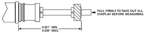
STEP 6: Pull distributor shaft out of distributor housing to eliminate endplay (see Fig. 1).
STEP 7: Check location of distributor gear on distributor shaft (see Fig. 1). If it is not in the correct location, use a press to move the gear to the correct location.
STEP 8: Using the vertical line on the distributor shaft and the noted dimension (see STEP 4), roughly plot where the original roll pinhole is located. Drill a new .125" hole 90° from the original hole, above or below it, through the gear and the shaft.
NOTE: It is important that the dimensions called out in Fig. 1 are maintained while drilling.
STEP 9: Insert roll pin and check dimensions (see Fig. 1).
WARNING: If the distributor gear is installed incorrectly, it may be forced down against the support in the block or may be held up away from the support in the block. Both conditions will cause damage to the block and or the block and gears. When the gear is properly installed, the cut on the gears and the direction of rotation will pull the distributor gear down against the support (distributor gear thrust face) in the block.
ALTERNATIVE METHOD OF VERIFYING CORRECT DISTRIBUTOR GEAR INSTALLATION:
After STEP 7, install distributor assembly in the block you are using. Timing chain set and camshaft must be removed. With the aluminum distributor housing fully seated against the block, verify that the distributor gear can be lifted off the support in the block at least .005". Next pull the distributor gear down against the support in the block and hold it there. Pull up on the aluminum distributor housing and verify that you can lift it up at least .005" while holding the gear against the support in the block. This procedure will confirm that the gear is not being forced down against the support and not being held up off the support in the block.
Continue with STEP 8.
COMMON DISTRIBUTOR PROBLEMS
Distributors with very little or no shaft endplay. This has been found with new and remanufactured distributors. Improper endplay may force the gear against the support in the block or hold it up off the support, causing damage.
Distributors that have a different material gear than advertised. It is important to run the correct distributor gear for the camshaft that you are using. Consult the manufacturer of the camshaft you are using for gear recommendation.
Some heavy-duty oil pump drive shafts may not allow an EFI distributor to slide down far enough over the oil pump drive shaft. EFI distributors have a longer shaft below the gear.
Running an HV oil pump with production bearing clearances can cause abnormally high oil pressure and possible premature distributor gear wear.
Gears on camshafts with a very poor finish. This could cause premature distributor gear wear. New and remanufactured distributors with the gear installed at the wrong height.
DISTRIBUTOR INSTALLATION:
STEP 1: To install the distributor correctly, the #1 piston must be at T.D.C. (top dead center), with the intake and exhaust valves closed.
STEP 2: Before removing distributor cap, mark the #1 post location on the distributor or cap adapter. Remove the distributor cap.
STEP 3: Rotate distributor shaft so the blade on the rotor is to the left of the mark, but as close to the mark as possible. As the distributor gear engages the teeth on the camshaft, the rotor will turn clockwise.
STEP 4: Install the distributor into the engine block opening. It may be necessary to slightly rotate the rotor/shaft assembly, until the drive gear "drops" into position. Sometimes rotation of the oil pump driveshaft is required to allow the distributor to drop all the way.
STEP 5: Verify rotor blade is pointing at the #1 mark on the distributor base.
NOTE: If rotor blade and magnetic pickup cannot be aligned by rotating the distributor in the engine block, remove the distributor enough to disengage distributor drive gear from camshaft gear. Rotate rotor enough to engage distributor gear on another camshaft gear tooth.
STEP 6: Repeat steps 3 and 4 if needed.
STEP 7: Install distributor hold-down clamp and bolt. Tighten bolt, but leave it loose enough to rotate the distributor.
STEP 8: Install distributor cap and wires.
STEP 9: Set timing. Tighten hold-down bolt.
COOLING SYSTEM
STEP 1: Fill cooling system (distilled/deionized water recommended).
STEP 2: The fill point of the cooling system must be the highest level of the cooling system.
STEP 3: Check for leaks.
STEP 4: After running engine and the cooling system is leak free, drain water and add appropriate amount of water/coolant.
TRANSMISSION
Most small block engines come equipped with 157-tooth manual transmission flywheels. The billet steel flywheels have multiple bolt patterns for different style pressure plates.
Sealer must be used on the small block flywheel to crankshaft bolts. Torque to 75-85 ft-lb. Over torquing will distort rear main seal area and cause leakage.
A starter index plate is required between the block and transmission bell housing (all applications). Be sure to install pressure plate alignment dowels if your pressure plate requires them. For other transmission applications requiring different flywheels, see catalog or call the Techline for other applications.
Verify that a pilot bearing is installed for all manual transmission applications. If using an automatic transmission, be sure the pilot bearing is removed.
Verify proper bellhousing alignment on manual transmission applications. See bellhousing alignment.
Check crankshaft endplay of your engine before installing the transmission. After installing the transmission, check crankshaft endplay. The number before and after installation should be the same. If endplay number is not the same, this indicates that the components are incorrect, or improperly installed or damaged.
HOW TO CHECK BELLHOUSING ALIGNMENT:
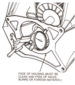
The first step is to check bellhousing face runout. You are checking for parallelism of the back of the bellhousing to the back of the block. Install the dial indicator (as shown in Fig. 2). Rotate the crankshaft and mark down the reading. Be sure to push the crankshaft against the thrust bearing for an accurate reading. Maximum runout is .010.
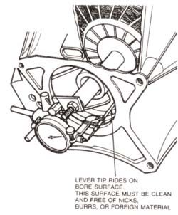
The next step is checking bellhousing bore runout. You are checking to see if the bellhousing bore centerline is aligned with crankshaft centerline. Reposition the dial indicator in the bellhousing bore (as shown in Fig. 3). Rotate the crankshaft and mark down the readings. Maximum out of concentricity is .015. If the bore runout is out of spec., install appropriate offset dowels.
Offset alignment dowels can be purchased from Lakewood.
.007 PN 15950
.014 PN 15960
.021 PN 15970
FLYWHEELS
The M-6007-X302 requires a 50 in-oz unbalance flywheel. Flywheel not included. See the flywheel page of the catalog or call the Techline at 1-800-367-3788.
IGNITION SYSTEM
The M-6007-X302 does not include a distributor. The distributor you select must have a steel distributor gear to be compatible with the hydraulic roller camshaft. Distributor gear M-12390-B for carbureted application or F for EFI application recommended.
NOTE: See engine tips sheet for recommended ignition timing.
OIL PANS
The M-6007-X302 comes with a production 1991-1995 Mustang rear sump oil pan. The oil pan may need to be changed to properly fit and function in your application.
VALVE COVERS
The M-6007-X302 comes with M-6000-K302R valve covers. Make sure the valve covers are correct for your application.
INDUCTION
- The M-6007-X302 does not include intake manifold. For carbureted applications, Performer RPM recommended.
- If you are using a different intake, verify that the intake gasket fits the ports on the cylinder head and intake manifold correctly before installing the intake manifold.
- M-9439-A50 intake gasket recommended.
FUEL DELIVERY
- 302 engines 600 cfm carb
- 24 lb. injectors up to 345 hp on 8-cylinder engine (naturally aspirated)
- 30 lb. injectors up to 430 hp on 8-cylinder engine (naturally aspirated)
- 31 lb. injectors up to 445 hp on 8-cylinder engine (naturally aspirated)
HEADERS
The horsepower numbers shown for the Ford Racing engines were obtained using long tube headers.
M-6007-X302 CRATE ENGINE FEATURES
- E303 Camshaft - automatic or manual transmission
- 306 cubic inch
- 340 hp @ 5500 rpm
- 9.0:1 compression ratio (nominal)
- Forged Mahle pistons 4.030”
- Aluminum Ford Racing “X” cylinder heads, M-6049-X306 with 1.94” intake valves and 1.54” exhaust valves production is 1.78”/1.45”)
- 50 in-oz imbalance rotating assembly (common to 1981 and newer 302s)
- Seasoned block and precision ground crankshaft
- “Ford Racing” polished aluminum valve covers M-6000-K302R, optional valve covers sold separately
- Production forged steel connecting rods
- New production 4-bolt crankshaft damper M-6316-M50
- Hydraulic roller camshaft M-6250-E303, .498" lift intake and exhaust, duration at .050" is 220 degrees intake and exhaust
- Double roller timing chain set
- New rear sump oil pan M-6675-A50, fits most Fox body cars
- New oil pump
- Water pump not included. Use water pump M-8501-G351 for standard rotation applications. Water pump M-8501-C50 for reverse rotation applications, 1986-1993 Mustangs. For short serpentine or 1994-1995 Mustangs use kit M-8501-A50. For short V-belt use water pump M-8501-E351S. For full details see other water pumps and timing chain covers
- lywheel not included. Requires 50 in-oz imbalance flywheel M-6375-B302 (T-5) or flexplate M-6375-A50 (AOD)
- Can be used in kit cars, street rods, Mustangs, Fox-bodied cars, and trucks
- IMPORTANT WARRANTY INFORMATION! Power-adders such as superchargers, turbos, or nitrous are not recommended. Use of power-adders voids the warranty. See Ford Racing BOSS series of crate engines such as M-6007-X302B or M-6007-X302E if you plan power-adder enhancements
INSTALLATION NOTES:
See engine installation and tuning tips. Some or all of the following items may need to be changed from your original engine or modified for proper installation:
- A different performance oil pan and pickup may be required for your application. Call the Techline at 1-800-367-3788 for more information
- Ghe timing chain cover will work with most standard rotation water pumps
- Fuel pump eccentric M-6287-B302 installed, allows use of mechanical fuel pump
- For other transmission applications use the proper 50 in-oz imbalance flywheel
- Intake gaskets M-9439-A50 required
- Firing order 1-3-7-2-6-5-4-8 (5.0L HO and 351W order)
- Built with current available parts. Photo and specs may vary
- Shipping weight approximately 425 lbs
QUICK INFO
- Intake bolt torque: 16 to 18 ft-lb in 3 steps
- Oil: 5 qts 10W30 or 10W40
- Timing: 14 to 16 degrees initial, 36 to 38 total with carburetion. 14 to 16 initial with factory EFI
- Fuel delivery: 600 cfm carburetor, 30 lb injectors EFI
- Distributor gear: steel
