 FREE 1 to 3-Day Delivery on Orders $149+ Details
How to Install a Ford Racing Intake Manifold Gasket on Your 1979-1995 5.0L Mustang
Installation Time
1 hours
Tools Required
- Jack with pair of jack stands and wheel chocks
- Torque wrenches (one inch lbs and one in foot lbs)
- Breaker bar ½” drive
- Large pry bar
- Rubber mallet
- Razors and gasket scraping/cleaning materials (wire brushes etc.)
- ¼”, 3/8” and ½” ratchets
- Socket and wrench set with the following sizes: 1 1/8”, 1 1/16”, metric 8mm through 20mm, standard size 5/16” through ¾”
- Extension bars of 6” and 9” length in 3/8” and ½” drive
- Universal joint sockets 3/8” and ½”
- Approximately 1 gallon of coolant
- Oil and filter
- Fuel line disconnect fittings, size ½” and 5/8”
- Torx head bits: T-20 for upper plenum cover and T-45 for belt tensioner center bolt.
- Timing light

Shop Parts in this Guide
Approximate Installation Time: Around 1 hour.
Parts required to accompany the installation of Intake Manifold Gaskets:
New lower intake manifold bolts
RTV silicone (Gray is a good choice)
Gasket sealant optional
Tools Needed:
Jack with pair of jack stands and wheel chocks
Torque wrenches (one inch lbs and one in foot lbs)
Breaker bar ½” drive
Large pry bar
Rubber mallet
Razors and gasket scraping/cleaning materials (wire brushes etc.)
¼”, 3/8” and ½” ratchets
Socket and wrench set with the following sizes: 1 1/8”, 1 1/16”, metric 8mm through 20mm, standard size 5/16” through ¾” (A large adjustable wrench can be substituted for 1 1/8” and 1 1/16” socket sizes for EGR air tub and ECT sensor/coolant crossover tubing.)
Extension bars of 6” and 9” length in 3/8” and ½” drive
Universal joint sockets 3/8” and ½”
Approximately 1 gallon of coolant
Oil and filter (For oil change after finished)
Fuel line disconnect fittings, size ½” and 5/8”
Torx head bits: T-20 for upper plenum cover and T-45 for belt tensioner center bolt.
Timing light
Special Notes:
This guide was written while working on a 1995 Mustang GT 5.0, other year 289/302 engines have identical instructions for installation of the gaskets, however removal of the intake manifold will differ due to differences in engines over the years.
What comes in the box:
2) Intake manifold gaskets
2) EGR Block off gaskets (If you deleted EGR or your cylinder heads do not have EGR provisions)
2) EGR adapter gaskets (These inserts are not necessary)
2) Cork gaskets (Not necessary if you want to use RTV silicone)
1. Place vehicle on flat surface and apply emergency brake, chock wheels.
2. Disconnect battery.
3. Carefully relieve pressure from fuel system (Have rags handy to soak up fuel when opening Schrader valve on fuel rail).
4. Using screwdriver, begin removal of air intake tubing. Loosen clamps and pull off of throttle body. Disconnect intake air temperature sensor (IAT) from air inlet tubing. If using factory airbox or a cold air intake (CAI) you can leave the airbox/CAI in place on fenderwell.
5. Remove the throttle return spring being careful it does not go flying.
6. Rotate the throttle body wide open with one hand, the other use to pop out the throttle cable with the slack in the line created. Pop off cruise control cable if equipped (Photo 1)
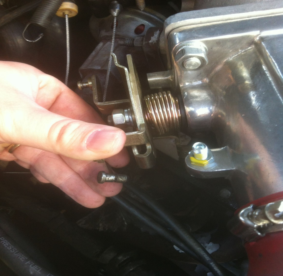
Photo 1: Rotating throttle to remove cable.
7. Remove the two 10mm bolts that secure throttle cable to intake.
8. Remove vacuum lines from upper plenum, EGR and fuel pressure regulator. Be careful with hard emissions vacuum hoses as they typically are very brittle.
9. Unplug Exhaust Gas Recirculation sensor (EGR), Throttle Position Sensor (TPS) and Idle Air Control valve (IAC).
10. For 94-95’ models the EGR is plumbed directly into the passenger exhaust manifold. Fox body EGR removal is easier, please refer to repair manual for removal. Using 1 1/8” wrench, or a large adjustable wrench, carefully loosen EGR air tube from intake manifold and at the exhaust manifold. If the fitting at the exhaust manifold does not budge, you can leave it in place and just disconnect the top for now. (Photo 2)
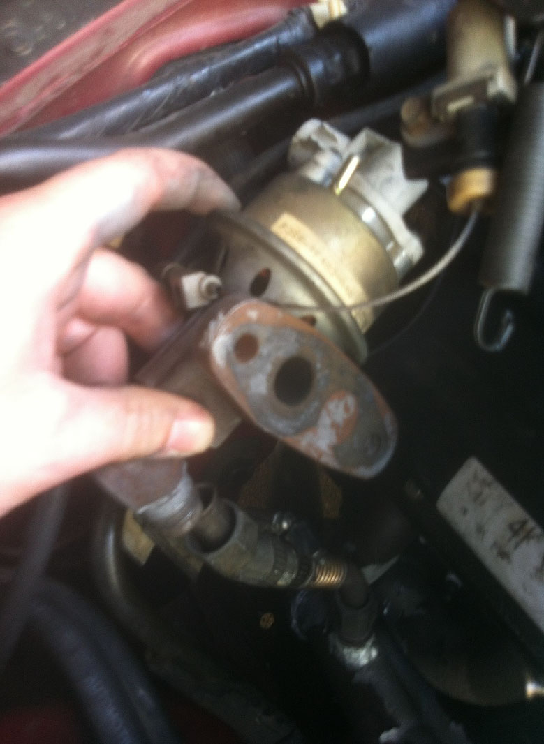
Photo 2: 94-95’ Models have EGR plumbed directly into passenger exhaust manifold.
11. Remove upper plenum cover using Torx T-20 bit. Using ½” socket begin to loosen the 6 upper plenum bolts securing the upper plenum to the lower intake manifold. Once all bolts are free the plenum should easily come off, the upper plenum gasket if intact is reusable if you need to do so. Make sure intake is completely free of all vacuum lines before pulling off to avoid breaking anything. Place rags over the intake to prevent debris or parts from entering the motor. (Photo 3)
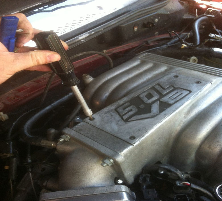
Photo 3: Torx T-20 for plenum cover. 6 bolts (1/2”) secure upper plenum to lower.
12. Next, take screwdriver and a drip pan and prepare to drain the block and heads of coolant. Place drip pan underneath water pump and loosen the lower radiator return hose and allow coolant to drain. I prefer to drain from the motor first, because you end up saving most of your coolant as opposed to draining directly from the radiator which drains all of it from the system, that is to say if you wanted to save coolant, mine was recently changed so I opted to save what I could.
13. Loosen the two front coolant hoses, one small one that connects to the thermostat housing and water pump, the other connects to the metal coolant crossover tube on the intake manifold.
14. Loosen and remove the upper radiator hose.
15. Loosen and remove two coolant hoses from the passenger side firewall that connect to the heater core.
16. Unplug engine coolant temperature (ECT) sensor from coolant crossover tube on intake manifold. Using 1” or adjustable wrench remove ECT sensor. Unplug the engine temperature sensor (dashboard temp gauge) from lower intake driver side. (Photo 4)
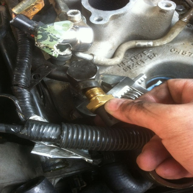
Photo 4: Removal of ECT from coolant crossover tube (fox models similar).
17. On 94-95’ 5.0 models the coolant crossover tube is only connected to the intake in the front, on fox body models it is connected in two places, front and back. Using 1 1/16” wrench or adjustable wrench, loosen the coolant crossover tube fittings. One bolt secures the tube to the lower intake manifold, remove the nut and the coolant crossover tube is free, use caution as it likely has remaining coolant inside of it. (Photo 5)
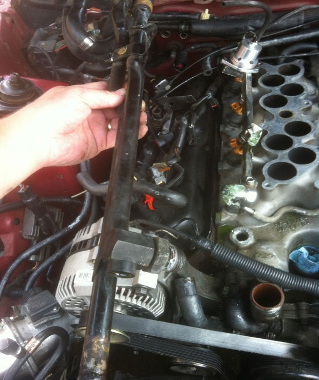
Photo 5: Coolant crossover tube 94-95’ models. Fox will have two connections to lower intake as well as small coolant line that runs through EGR spacer on upper plenum
18. Using quick disconnect fuel line fittings, remove the two fuel lines from the fuel rails. Pop off the metal snap locks and place rags underneath to catch any fuel spills. Cover the fuel lines and the openings of the fuel rails to prevent contamination. (Photo 6)
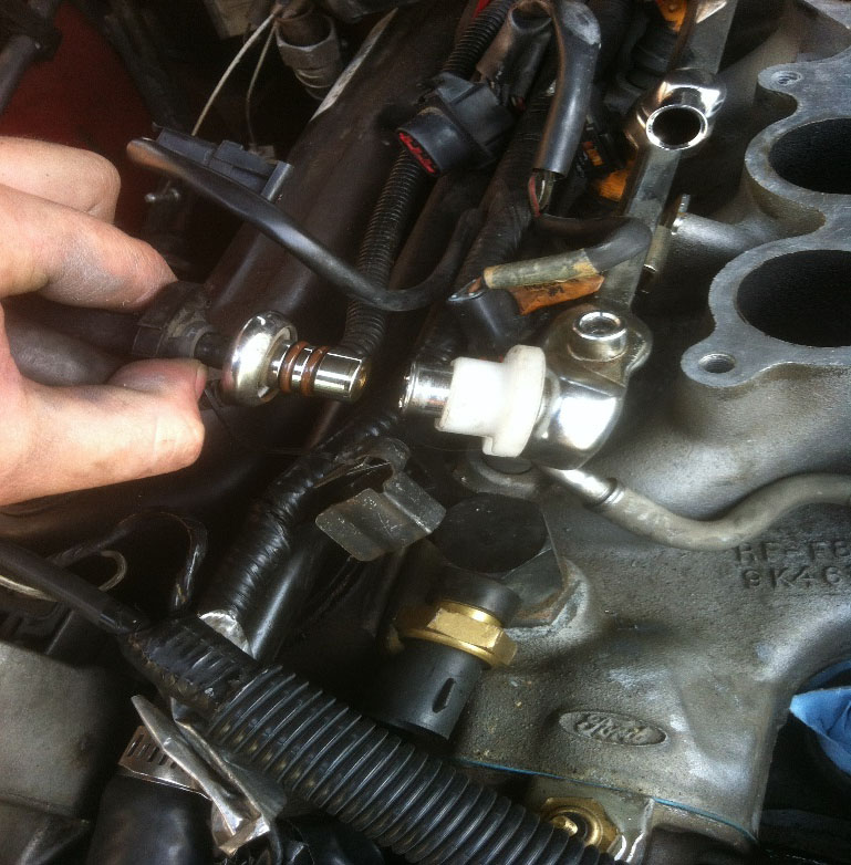
Photo 6: Using disconnect tool to unhook fuel lines. Don’t lose metal snap locks.
19. Disconnect fuel injector harnesses carefully, the tabs on them are very brittle. Disconnect the Distributor harness and ignition coil harness.
20. Disconnect the Alternator wiring. One 10mm nut secures the main cable, I like to put the nut back on for safe keeping so it does not get lost. (Photo 7)
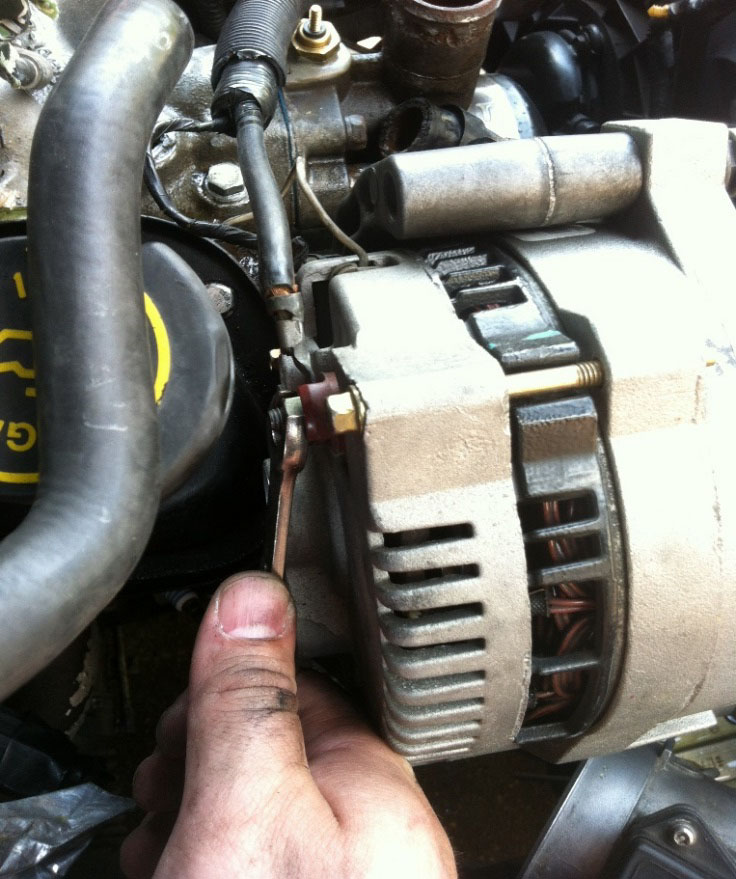
Photo 7: Removal of alternator wiring 94-95’ models (Fox similar).
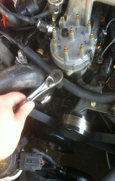
21. Label and remove all spark plug wires and ignition coil wire. (Photo 8)
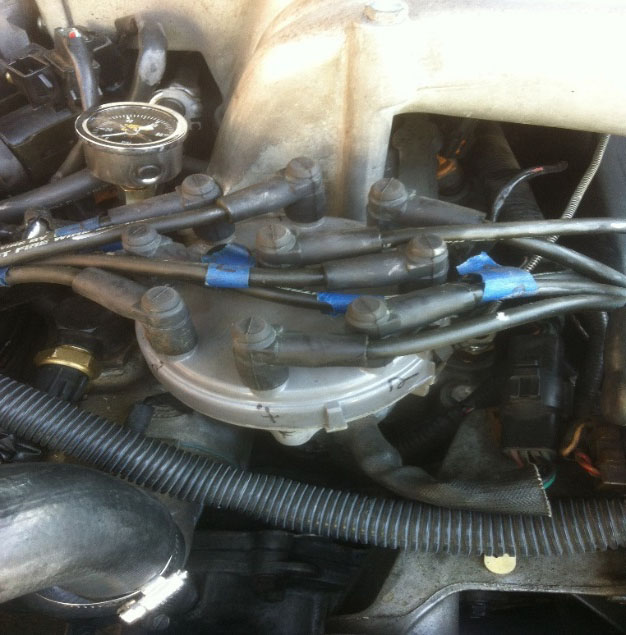
Photo 8: Labeling distributor cap and plug wires for convenience later on.
22. Remove the distributor hold down bolt, a special ½” distributor wrench is inexpensive and makes the job much easier. Either crank engine by hand with a 1” socket until engine is at #1 cylinder top dead center, or mark the position of the distributor and rotor to the engine so they reinstall in identical position. Be careful removing it, if the oil pump driveshaft is stuck to the distributor make absolutely sure you don’t drop it into the hole. As it will go into the oil pan and cause a whole new job to drop the pan in order to retrieve it! Take a clean rag and place it in the distributor hole to prevent contamination. (Photo 9)
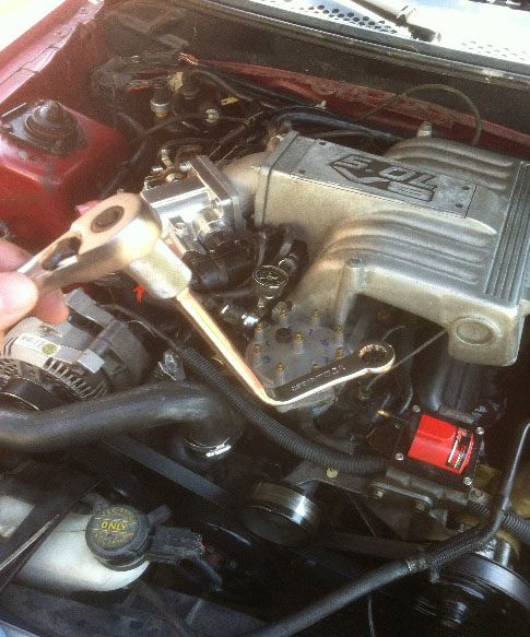
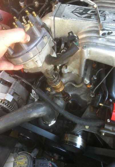
Step 22. Photo 9: Using distributor wrench to remove ½” bolt securing distributor.
23. Begin unbolting the lower intake manifold using ½” socket. It is not advised to reuse intake manifold bolts due to stretching, but keep them safe for now. (Photo 10)
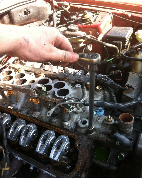
Photo 10. Unbolting the 12 lower intake manifold bolts.
24. Once all 12 intake manifold bolts are removed, take a pry bar or large flat screwdriver and a rubber mallet and gently pry up the intake manifold using gentle force. It should only take a tap or two with the mallet to break the seal. As you carefully lift up the intake manifold, be careful of coolant left inside of it. Once removed, set it aside in a clean location for later. Drape rags over the lifter valley to protect the motor from debris. (Photo 11)
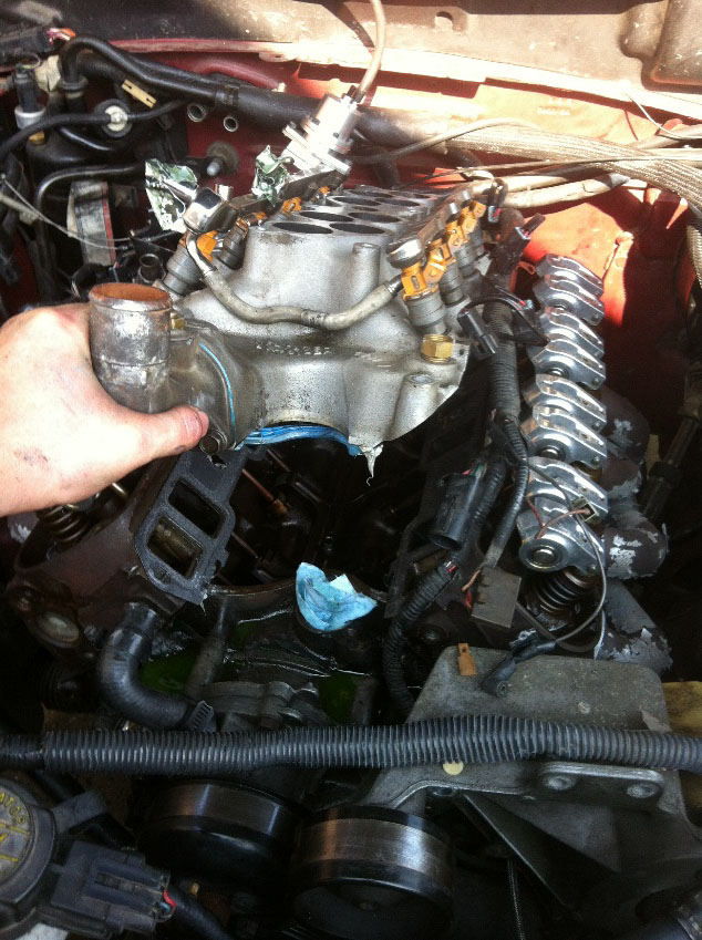
Photo 11. Prying the lower intake manifold up to break old gasket seals.
25. Clean up your old lower intake manifold and make sure it is immaculate. Often times, corrosion occurs around the coolant passages. A dab of RTV ultra gray works well, super lightly coat the area around coolant passages when ready to install.
26. Take four old intake manifold bolts and cut the heads off of them and grind a mark in top of each so a screwdriver can fit them, these will be very handy for installing intakes now and in the future. (Photo 12)
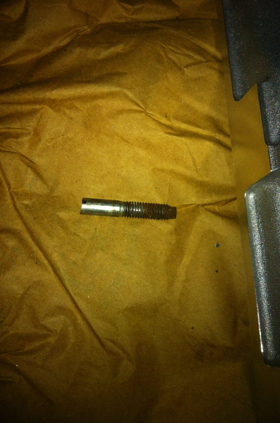
Step 26. Photo 12: An old intake bolt with head cut off and a slit grinded into it makes a great stud to not only help hold intake gaskets in place but to guide the intake down over it and make the job much easier. The slit in the tip is to be able to take a screwdriver and remove them easily when done with them.
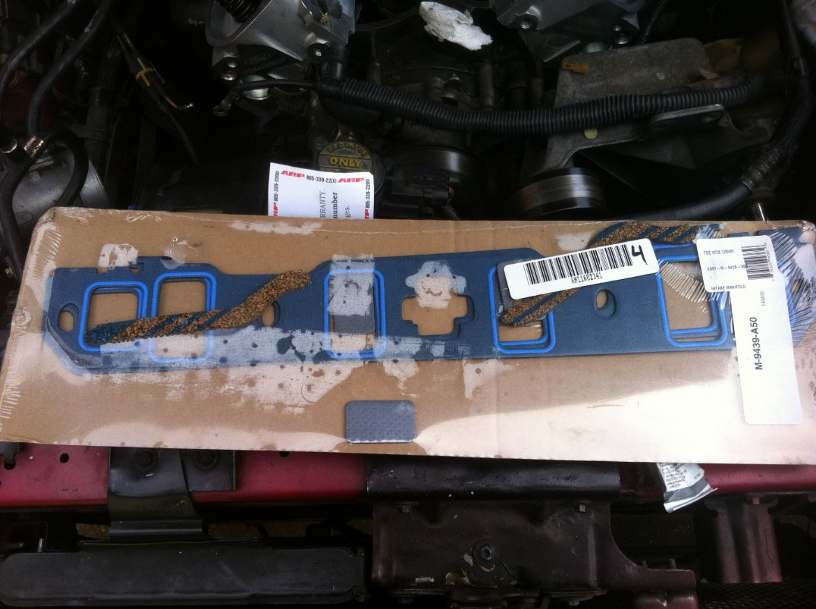
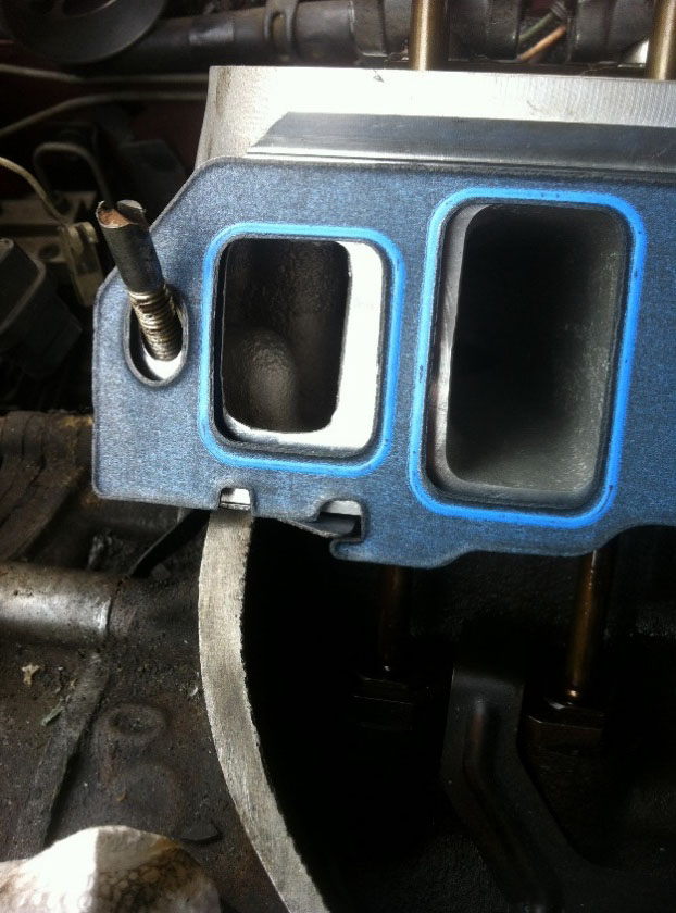
27. Depending on the intake manifold you are using, the port alignment may not be the same with these gaskets because they are slightly thicker than OEM. If the intake sits too high up or too low then the intake gaskets will likely leak, I used an Explorer intake that was recommended to Ford Racing intake manifold gasket kit with my GT40X heads #50265 (Ford Racing part number M-9439-A50). (Photo 13)
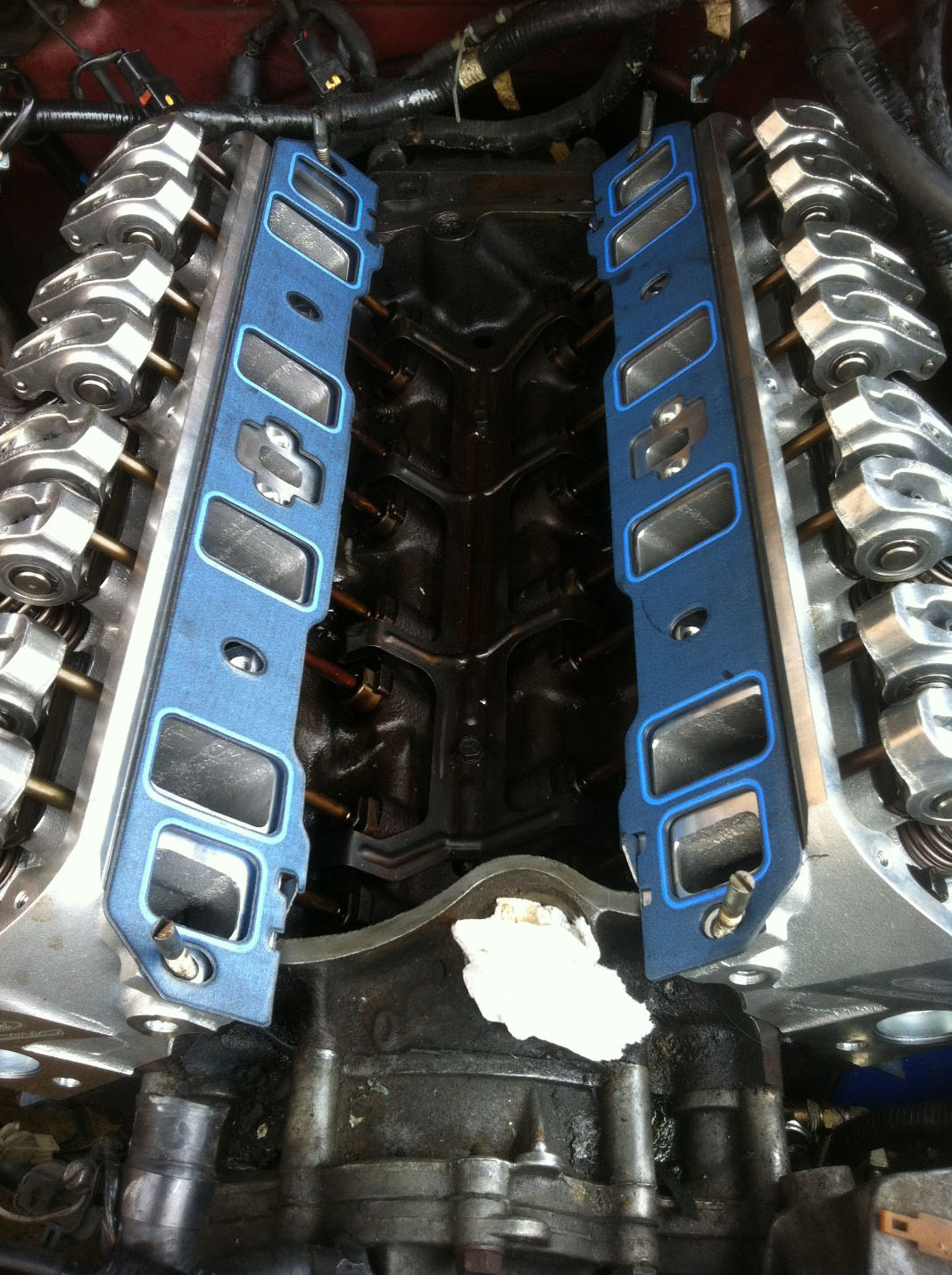
Photo 13: Always check port alignment of your gaskets between the cylinder head and intake, test fit your intake without bolting it down first.
28. If port alignment matches, place the four cut intake bolts into the heads and slip the intake manifold gaskets into place. The supplied cork gaskets have tape on them so remove the backing and lay them in place. Put a dab or RTV in the corners of the gaskets where it meets the cylinder heads. Use a gasket sealant or light coat of RTV over the cork gaskets, or discard the cork and just use RTV alone, any of which is fine. (Photo 14)
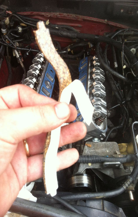
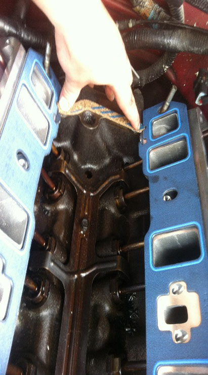
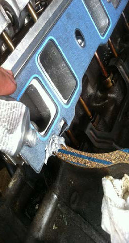
Photo 14: Applying cork gaskets and putting RTV silicone in corner of each. It is also perfectly acceptable to just use RTV by itself if desired.
29. Place your lower intake manifold into place, the cut intake bolts will act as guides to hold the gasket in place while the intake is lowered down. Once in place, take your new intake manifold bolts and begin to thread by hand. I put a small dab of assembly lube to the threads of each bolt, some prefer anti seize and others nothing at all which is all fine. Thread all bolts down by hand.
30. The intake manifold will be torqued in three steps. Following Photo 15 you can see the torque sequence. First step will be 96 inch lbs. Second step will be 10 foot lbs. Third and final step will be 20 foot lbs. Do not move on to the next torque sequence until torque reading is reached on every bolt, it does not matter how many times you must go over this sequence. I had to go over my intake for the final 20 foot lbs about 5 times before every bolt read the correct amount of torque. I also highly recommend you walk away for 24 hours before coming back and starting the engine. This gives plenty of time for any RTV or gasket sealants to set and gaskets to compress. I came back the next day and re-torqued the intake manifold and needed to go over it another 3 or 4 times before all the bolts reached specs. (Photo 15)
Photo 15: Intake manifold torque sequence. I had to go over my intake on the last step about 5 times to get 20 foot lbs. It is highly recommended when done with this step to wait one full day before starting so all RTV sealant dries and gaskets compress, then retorque again to 20 foot lbs.
31. With the intake now in place, reassembling the motor is the reverse steps 25 through 1. Reinstalling the Distributor. If you did not turn over the motor and marked the relationship of the distributor and rotor then just drop it back in exactly as you removed it. If for any reason you did not mark it, or did other work and turned the motor over then relocate TDC for cylinder #1. An easy way is remove cylinder number 1 spark plug and while turning over engine with 1” socket on a breaker bar feel the spark plug for when air begins to escape, you should feel it on your finger in the spark plug hole as well as hear the noise it is making. Soon as the air stops escaping the cylinder is approaching the top, so then all you have to do is shine a light on your vibration dampener and rotate the motor until it reads zero on your timing marks, you are now at top dead center and can install the distributor with the rotor facing the number 1 on the distributor cap. Always double check base timing when you are all finished.
32. Top off coolant and burp the system to remove air pockets. Change your oil after completing the job to make sure any leaked coolant in the oil does not cause engine damage. I drove for a few days, then pulled off the upper plenum one more time and re-torqued lower intake back to 20lbs and double checked all hose clamps and rechecked base timing.
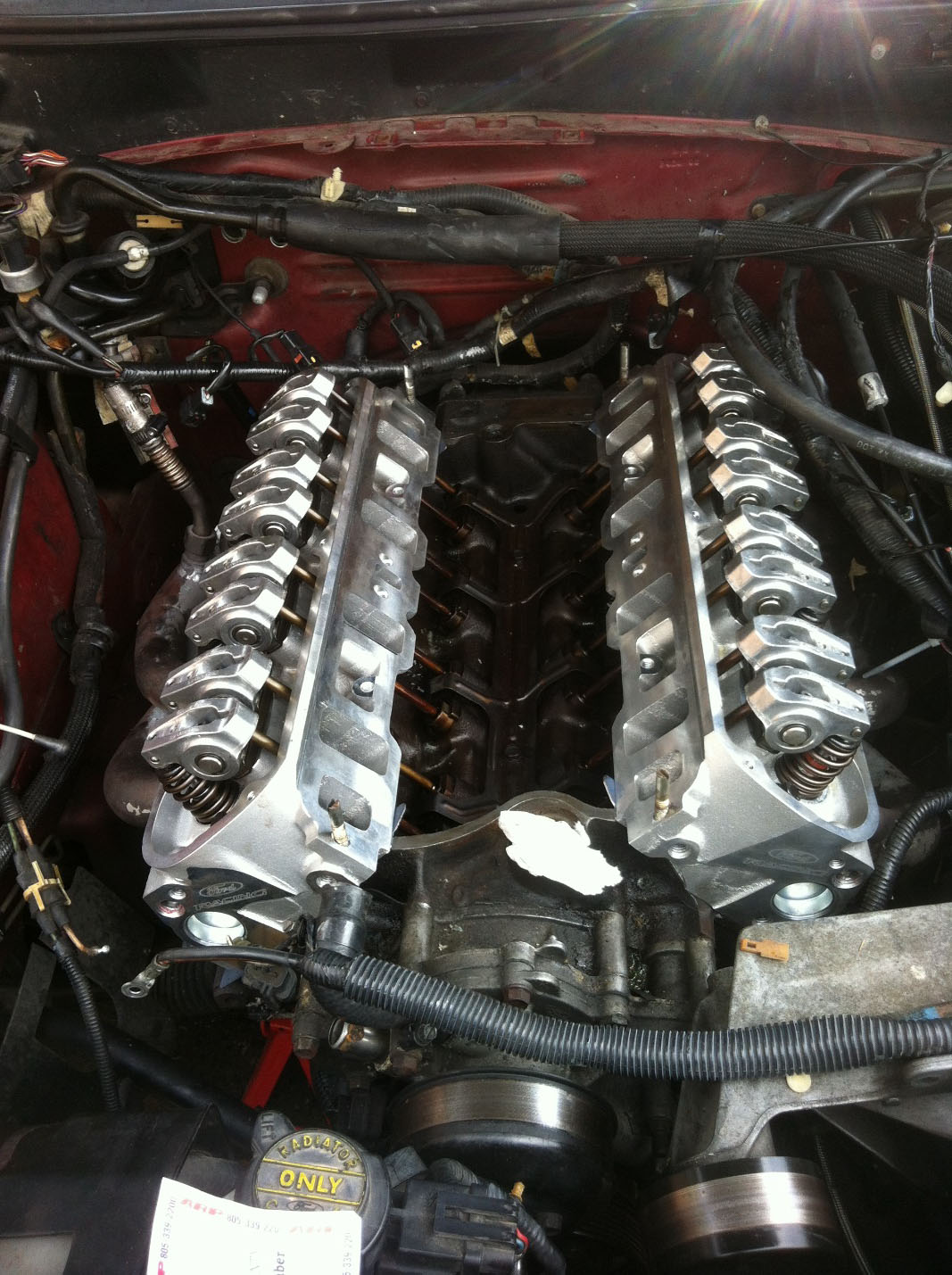
BEFORE
Gasket surfaces prepped and ready to place gaskets.
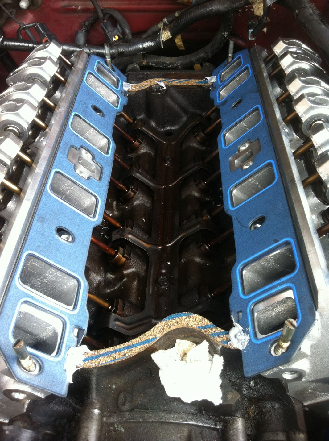
AFTER
Gaskets in place and ready to place intake manifold on and torque down.
Installation Instructions written by AmericanMuscle Customer Edward McSwain 9.14.2014
