FREE 1 to 3-Day Delivery on Orders $149+ Details
How to Install a Ford Racing Turbo-Swirl GT40X Aluminum Head 64CC Chamber in Your 1982-1995 Mustang
Installation Time
8 hours
Tools Required
- Jack with pair of jack stands and wheel chocks
- Clean well lit work environment
- Power Steering puller/installer tool
- Penetrating fluid
- Torque wrenches (inch lbs and one in foot lbs)
- Breaker bar ½” drive
- Large pry bar
- Rubber mallet
- Razors and gasket scraping/cleaning materials (wire brushes etc.)
- ¼”, 3/8” and ½” ratchets
- Socket and wrench set with the following sizes: 1 1/8”, 1 1/16”, metric 8mm through 20mm, standard size 5/16” through ¾”
- Extension bars of 6” and 9” length in 3/8” and ½” drive
- Universal joint sockets 3/8” and ½”
- Oxygen sensor socket
- Approximately 1 gallon of coolant
- Oil and filter
- Fuel line disconnect fittings, size ½” and 5/8”
- Serpentine belt tool
- Torx head bits: T-20 for upper plenum cover and T-45 for belt tensioner center bolt.
- OBD-I code scanner
- Timing light
Approximate Installation Time: 6-8 hours for novice.
Parts required to accompany the installation of heads (If Applicable):
• If using a GT40 style intake (Cobra, Tubular GT40,) it is highly recommended to use Ford Racing Intake Gasket Set. Item # 50265, reason being the gasket is .065” and helps port matching the intake to the heads. Always do a test fit and shine light into the intake to view the port match before doing install. Not all intakes fit perfectly and may create vacuum leaks if the wrong gasket used.
• Must use special step washers for installing GT40X heads (Heads have larger ½” bolt holes for 351 motors, stock 302 has smaller 7/16” diameter head bolts). I used Item #50146, which is Ford Racing 289/302 head bolt kit that has the required washers.
• Valve cover gasket set. I used Item # 50264 from American Muscle.
• Upper plenum gasket. (Cobra/GT40 intake style: Item # 50585 on American Muscle)
• Exhaust manifold gasket set. Item # 50257 (fits stock as well as many aftermarket headers on market.) Test fit your header to the cylinder head prior to install, the exhaust ports are much larger than stock E7TE heads and single flange headers are difficult to seal without the correct gasket. I prefer to use a good quality copper spray-a-gasket with the installation of exhaust manifold gaskets.
• Head gasket set. For this install I used American Muscle Item # 50118.
• Pedestal rocker arm shim kit (If proper rocker arm geometry/preload unable to be achieved) Item # 50310 on American Muscle.
• Longer or shorter pushrods if necessary (Depending on cam, rocker arms and lifters utilized it may be necessary to purchase pushrods of correct length. A pushrod length measurement tool is handy and inexpensive to determine size you require.)
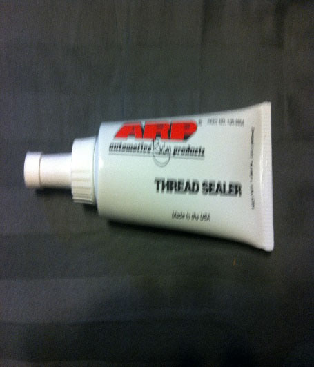
• ARP thread sealant (Item # 18221 from American Muscle)
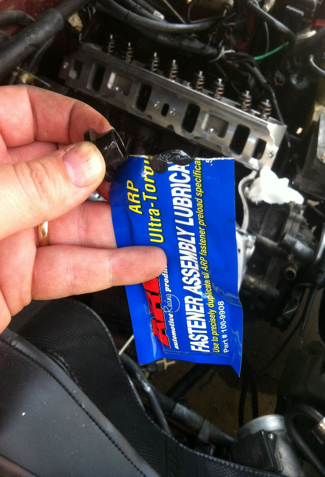
• Assembly lube (Item # 18222 from American Muscle) comes with the Head bolt kit #50146. .
• GT40X heads call for AGSF-32C or equivalent spark plugs. American Muscle sells TR-55 NGK V power plugs Item # 64021 (Used in this installation guide)
Tools Needed:
• Jack with pair of jack stands and wheel chocks
• Clean well lit work environment
• Power Steering puller/installer tool
• Penetrating fluid
• Torque wrenches (inch lbs and one in foot lbs)
• Breaker bar ½” drive
• Large pry bar
• Rubber mallet
• Razors and gasket scraping/cleaning materials (wire brushes etc.)
• ¼”, 3/8” and ½” ratchets
• Socket and wrench set with the following sizes: 1 1/8”, 1 1/16”, metric 8mm through 20mm, standard size 5/16” through ¾” (A large adjustable wrench can be substituted for 1 1/8” and 1 1/16” socket sizes for EGR air tub and ECT sensor/coolant crossover tubing.)
• Extension bars of 6” and 9” length in 3/8” and ½” drive
• Universal joint sockets 3/8” and ½”
• Oxygen sensor socket (If factory mid pipe the 02 sensors obstruct reaching collector nuts and is easier to remove the 02 sensors.)
• Approximately 1 gallon of coolant
• Oil and filter (For oil change after finished)
• Fuel line disconnect fittings, size ½” and 5/8”
• Serpentine belt tool (Or use ½” breaker bar etc.)
• Torx head bits: T-20 for upper plenum cover and T-45 for belt tensioner center bolt.
• OBD-I code scanner, or knowledge of how to do paperclip/needle sweep method to read any trouble codes that may occur.
• Timing light
Helpful Hint Before Starting:
If able to, the night prior to the installation, warm car up to normal operating temperature and spray penetrating oil on engine and allow to soak overnight. You particularly want to hit the lower intake manifold bolts and accessory bolts on front of engine, EGR air tube, exhaust manifold/header bolts and exhaust collector bolts. This will help in removal. The day of the installation don’t be afraid to soak it all again with penetrating oil for good measure. Power steering pump puller and installation tools are usually available for renting at local parts stores, be sure to acquire this as well as all the necessary tools and parts needed before beginning this project to avoid having to wait for parts to arrive by mail or have to drive out and hunt down last minute parts that were forgotten. Installation was done on a 1995 GT 5.0. 79-93’ models and all others will have many of the same basic steps of installing the cylinder heads, having a repair manual handy for your car is a good thing to have.
Special Notes: This guide is assuming the motor is remaining inside the vehicle. For installation of cylinder heads on an engine stand, skip ahead to step 35. This guide was written while working on a 1995 Mustang GT. Foxbody years will be slightly different in some steps.
1. Place vehicle on flat surface and apply emergency brake, chock wheels.
2. Disconnect battery.
3. Carefully relieve pressure from fuel system (Have rags handy to soak up fuel when opening Schrader valve on fuel rail).
4. Jack up car and support on jack stands. Remove the two 11/16” nuts on either side exhaust manifold collectors. An extension bar and universal joint makes the task easier. If oxygen sensors (02 sensor) are in the way, make sure you have an 02 sensor socket handy. Once both sides are free, lower vehicle back down to the ground. Take note of your lower radiator hose, if the clamp is not accessible from up top of the car, loosen it and manipulate it so you can reach it easily from above to make the job easier of draining the coolant system.
5. Using screwdriver, begin removal of air intake tubing. Loosen clamps and pull off of throttle body. Disconnect intake air temperature sensor (IAT) from air inlet tubing. If using factory airbox or a cold air intake (CAI) you can leave the airbox/CAI in place on fenderwell.
6. Carefully remove the throttle return spring being careful it does not go flying.
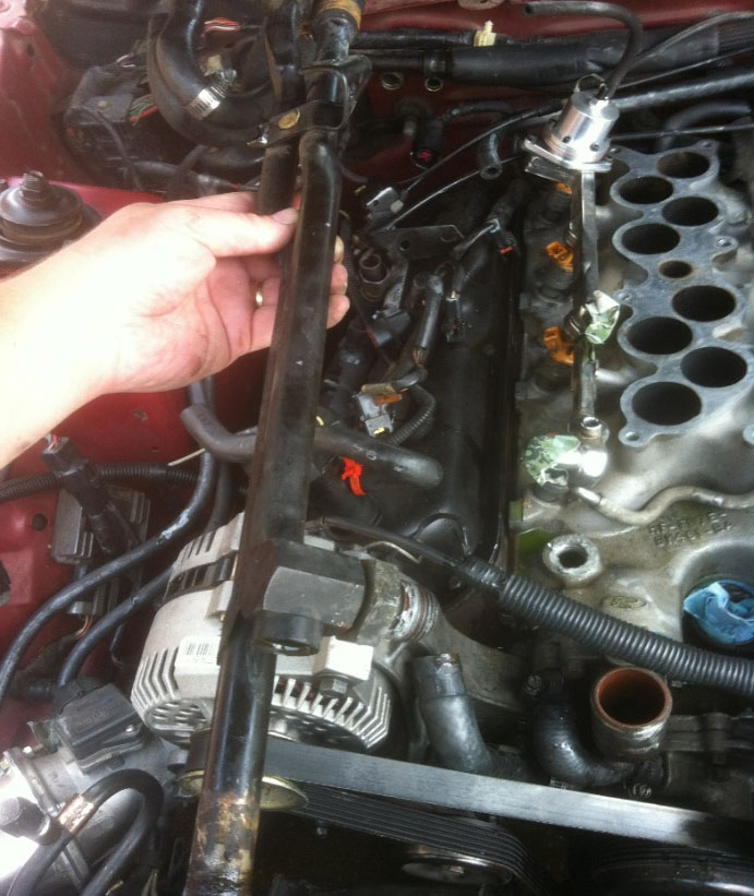
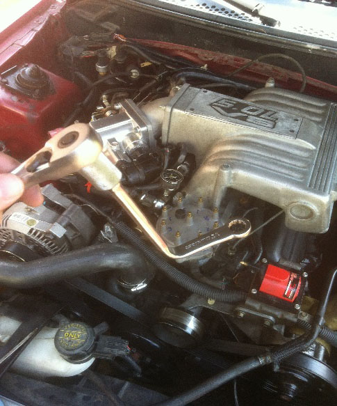
7. Rotate the throttle body wide open with one hand, the other use to pop out the throttle cable with the slack in the line created. Pop off cruise control cable if equipped (Photo 1)
Step 7. Photo 1: Rotating throttle to remove cable.
8. Two 10mm bolts secure throttle cable to intake.
9. Remove vacuum lines from upper plenum, EGR and fuel pressure regulator. Be careful with hard emissions vacuum hoses as they typically are very brittle.
10. Unplug Exhaust Gas Recirculation sensor (EGR), Throttle Position Sensor (TPS) and Idle Air Control valve (IAC).
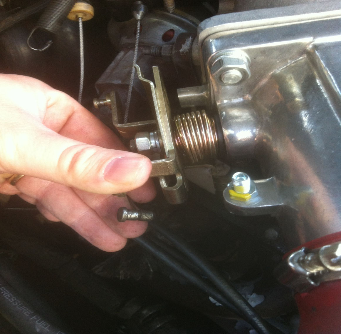
11. For 94-95’ models the EGR is plumbed directly into the passenger exhaust manifold. Fox body EGR removal is easier, please refer to repair manual for removal. Using 1 1/8” wrench, or a large adjustable wrench, carefully loosen EGR air tube from intake manifold and at the exhaust manifold. If the fitting at the exhaust manifold does not budge, you can leave it in place and just disconnect the top for now. (Photo 2)
Step 11. Photo 2: 94-95’ Models have EGR plumbed directly into passenger exhaust manifold.
12. Loosen all hose clamps and remove vacuum hoses of smog pump and all related tubing that mounts to the back of each cylinder head. Disconnect exhaust tubing from H-pipe that connects to the smog pump.
13. Remove upper plenum cover using Torx T-20 bit. Using ½” socket begin to loosen the 6 upper plenum bolts securing the upper plenum to the lower intake manifold. Once all bolts are free the plenum should easily come off, the upper plenum gasket if intact is reusable if you need to do so. Make sure intake is completely free of all vacuum lines before pulling off to avoid breaking anything. Place rags over the intake to prevent debris or parts from entering the motor. (Photo 3)
Step 13. Photo 3: Torx T-20 for plenum cover. 6 bolts (1/2”) secure upper plenum to lower.
14. Next, take screwdriver and a drip pan and prepare to drain the block and heads of coolant. Place drip pan underneath water pump and loosen the lower radiator return hose and allow coolant to drain. I prefer to drain from the motor first, because you end up saving most of your coolant as opposed to draining directly from the radiator which drains all of it from the system, that is to say if you wanted to save coolant, mine was recently changed so I opted to save what I could.
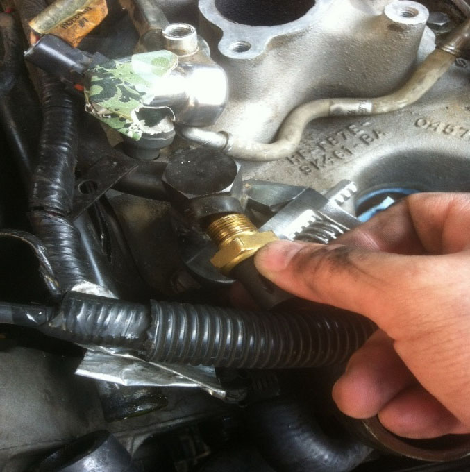
15. Loosen the two front coolant hoses, one small one that connects to the thermostat housing and water pump, the other connects to the metal coolant crossover tube on the intake manifold.
16. Loosen and remove the upper radiator hose.
17. Loosen and remove two coolant hoses from the passenger side firewall that connect to the heater core.
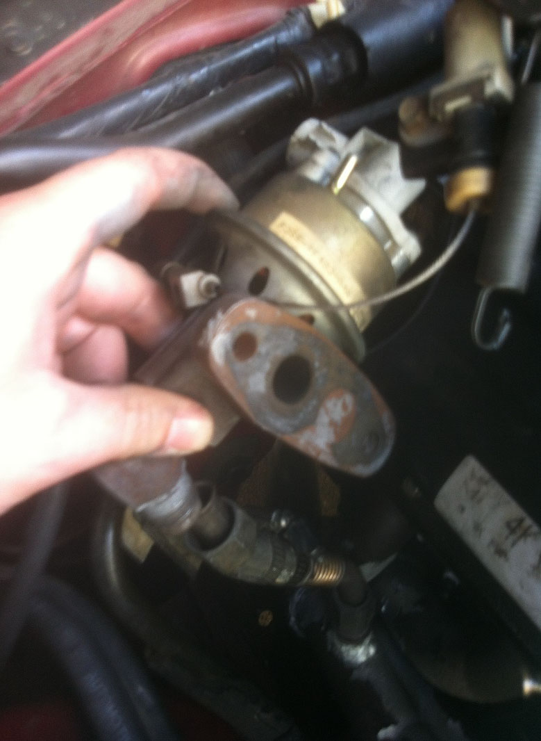
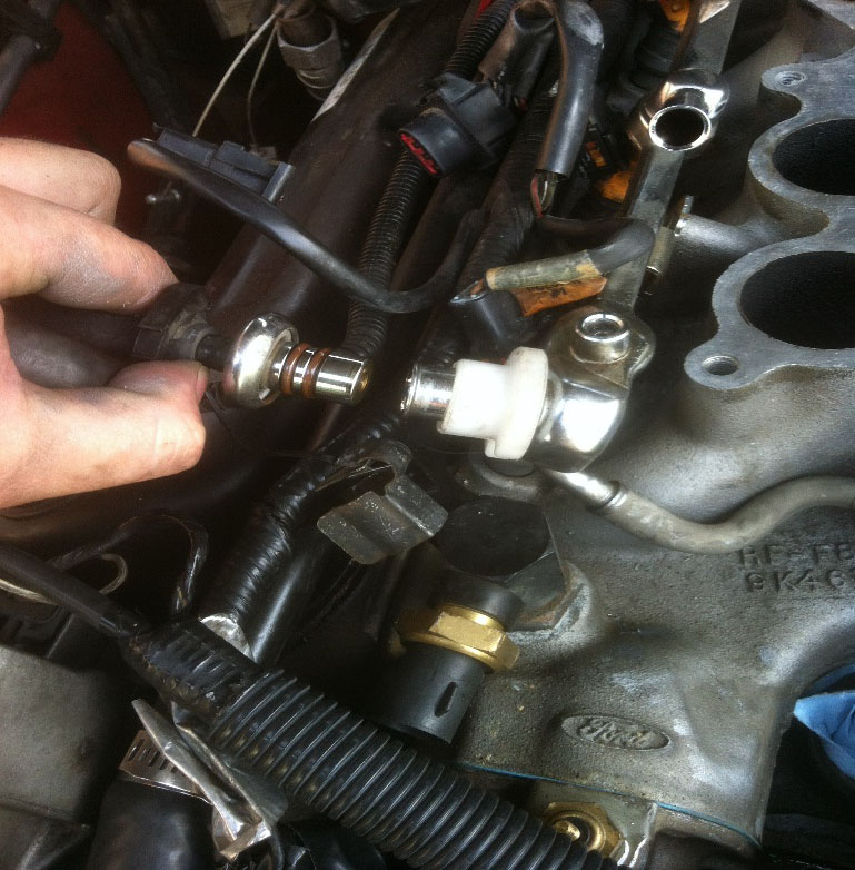
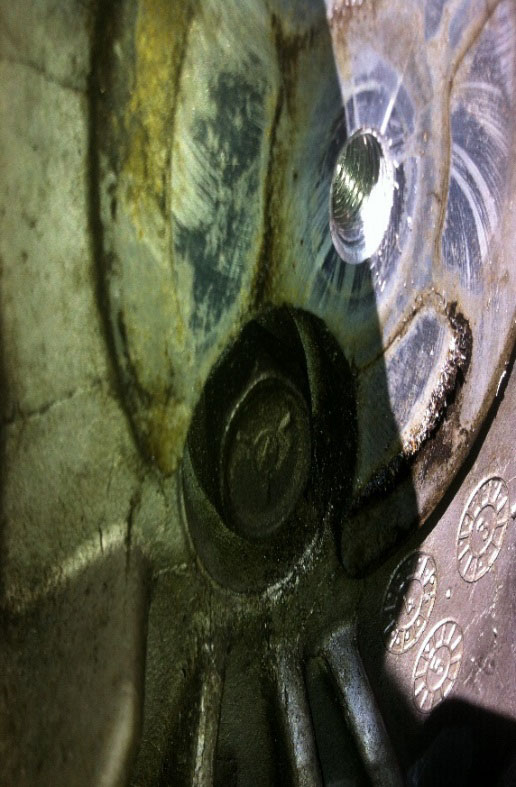
18. Unplug engine coolant temperature (ECT) sensor from coolant crossover tube on intake manifold. Using 1” or adjustable wrench remove ECT sensor. Unplug the engine temperature sensor (dashboard temp gauge) from lower intake driver side. (Photo 4)
Step 18. Photo 4: Removal of ECT from coolant crossover tube (fox models similar).
19. On 94-95’ 5.0 models the coolant crossover tube is only connected to the intake in the front, on fox body models it is connected in two places, front and back. Using 1 1/16” wrench or adjustable wrench, loosen the coolant crossover tube fittings. One bolt secures the tube to the lower intake manifold, remove the nut and the coolant crossover tube is free, use caution as it likely has remaining coolant inside of it. (Photo 5)
Step 19. Photo 5: Coolant crossover tube 94-95’ models. Fox will have two connections to lower intake as well as small coolant line that runs through EGR spacer on upper plenum.
20. Using quick disconnect fuel line fittings, remove the two fuel lines from the fuel rails. Pop off the metal snap locks and place rags underneath to catch any fuel spills. Cover the fuel lines and the openings of the fuel rails to prevent contamination. (Photo 6)
Step 20. Photo 6: Using disconnect tool to unhook fuel lines. Don’t lose metal snap locks.
21. Disconnect fuel injector harnesses carefully, the tabs on them are very brittle. Disconnect the Distributor harness and ignition coil harness.
22. Disconnect the Alternator wiring. One 10mm nut secures the main cable, I like to put the nut back on for safe keeping so it does not get lost. (Photo 7)
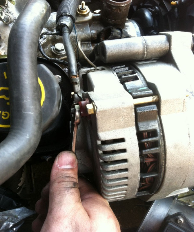
Step 22. Photo 7: Removal of alternator wiring 94-95’ models (Fox similar).
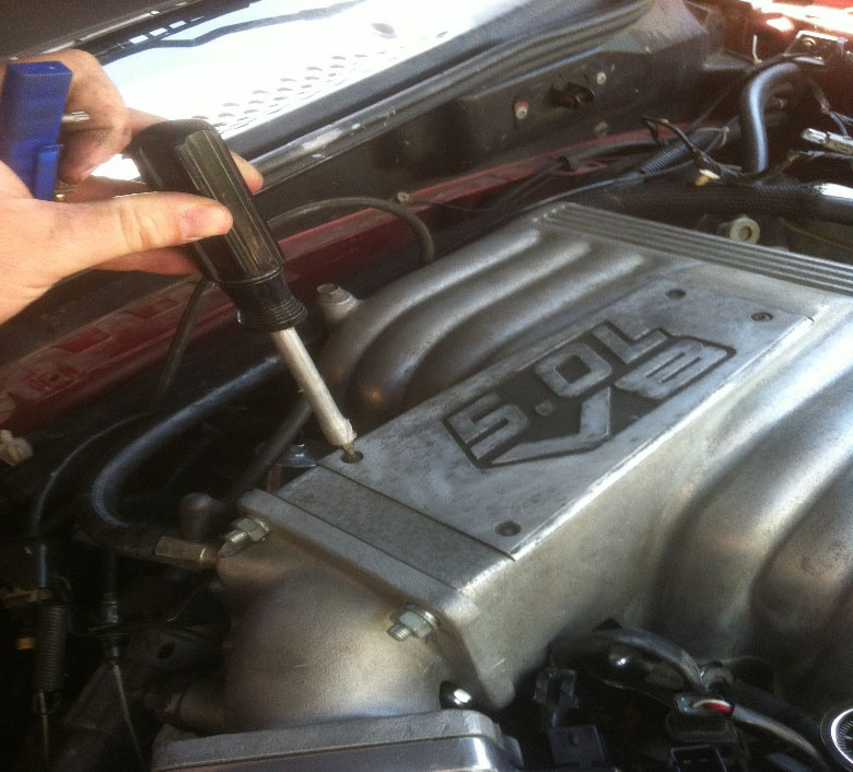
23. Label and remove all spark plug wires and ignition coil wire. (Photo 8)
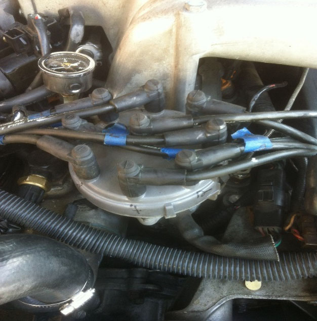
Step 23. Photo 8: Labeling distributor cap and plug wires for convenience later on.
24. Remove the distributor hold down bolt, a special ½” distributor wrench is inexpensive and makes the job much easier. The engine will need to be rotated several times in later steps, so marking the relationship of the distributor rotor is not needed, simply remove the distributor. I marked where the number 1 cylinder is on the inside the distributor to make installing it on the number 1 cylinder easier. Make careful note as removing it, if the oil pump driveshaft is stuck to the distributor make absolutely sure you don’t drop it into the hole, it will go into the oil pan and cause a whole new job to perform to drop the pan to retrieve it! Take a clean rag and place it in the distributor hole to prevent contamination. (Photo 9)
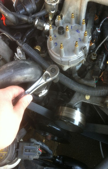
Step 24. Photo 9: Using distributor wrench to remove ½” bolt securing distributor.
25. Begin unbolting the lower intake manifold using ½” socket. It is not advised to reuse intake manifold bolts due to stretching, but keep them safe for now.
26. Once all 12 intake manifold bolts are removed, take a pry bar or large flat screwdriver and a rubber mallet and gently pry up the intake manifold using gentle force. It should only take a tap or two with the mallet to break the seal. As you carefully lift up the intake manifold, be careful of coolant left inside of it. Once removed, set it aside in a clean location for later. Drape rags over the lifter valley to protect the motor from debris.
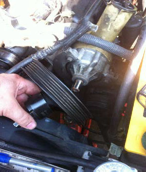
27. Remove the serpentine belt using 3/8” drive ratchet or serpentine belt tool, rotate clockwise to loosen belt and pull belt off one of the pullies.
28. Remove alternator by removing two bolts securing it to accessory bracket passenger side. (Photo 10)
Step 28. Photo 10: Removal of alternator from accessory bracket.
29. Using T-45 Torx bit, preferably one that is a socket on a 3/8” or ½” drive ratchet, loosen the center bolt of the belt tensioner and remove. An accessory bolt is underneath this tensioner that needs to be accessed. (Photo 11)
Step 29. Photo 11: Use Torx T-45 to remove belt tensioner to expose bolt underneath to remove accessory bracket from passenger cylinder head 94-95’ models (Fox similar).
30. Remove the three bolts securing the accessory bracket to the passenger side cylinder head. Smog pump may remain in place if desired.
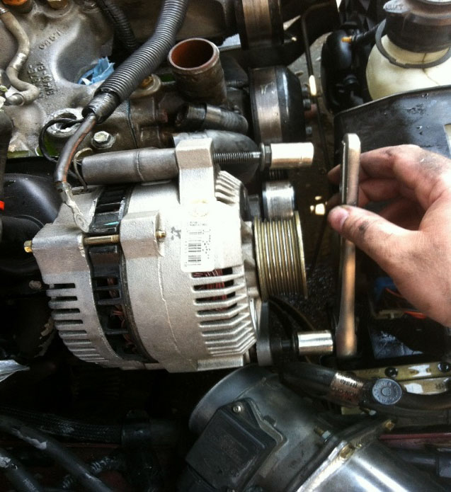
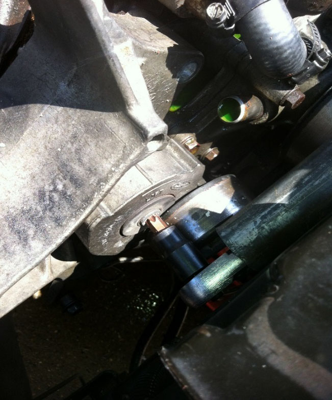
31. Using a proper power steering removal tool is required to remove the pulley to access an accessory bracket bolt underneath the pulley. Many parts stores rent out this equipment free of charge. The kit I purchased is a puller and installer tool in one. (Photo 12)
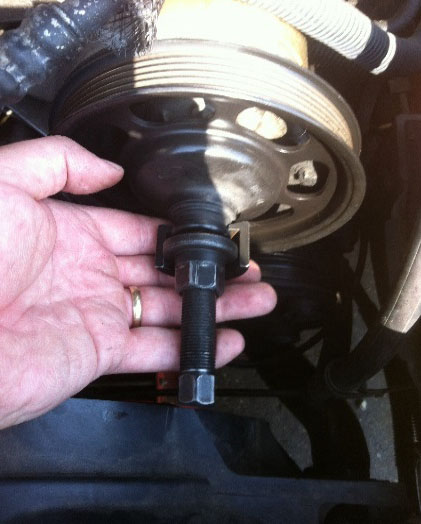
Step 31. Photo 12: Using proper power steering puller to remove pulley to gain access to bolt underneath that secures driver side accessory bracket to cylinder head.
32. One small 8mm bolt secures the air conditioning line to the ignition coil on 94-95’ models. Two 10mm bolts secure the ignition coil to the accessory bracket, remove this to allow the accessory bracket to move more freely away from the motor. (Photo 13)
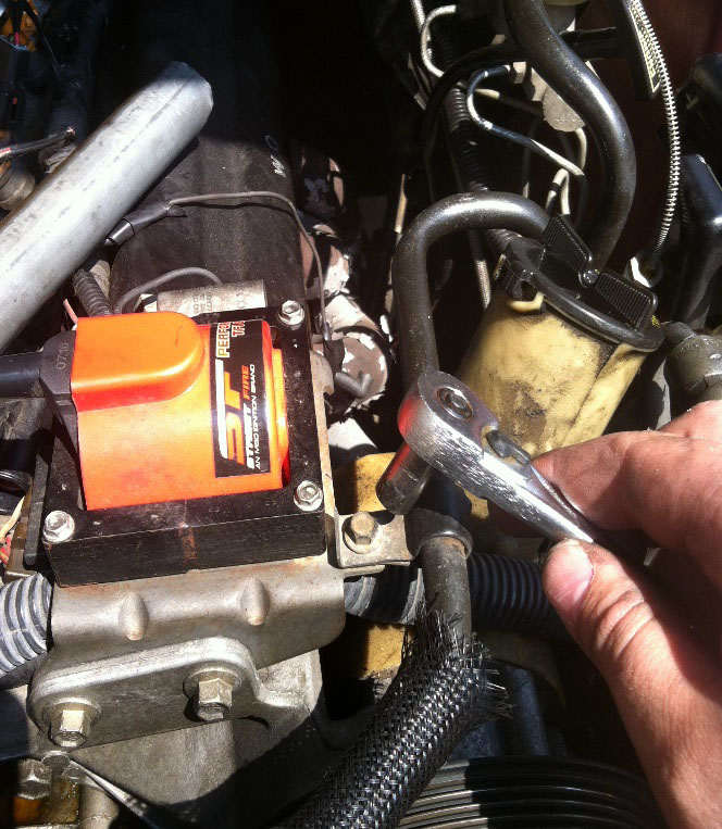
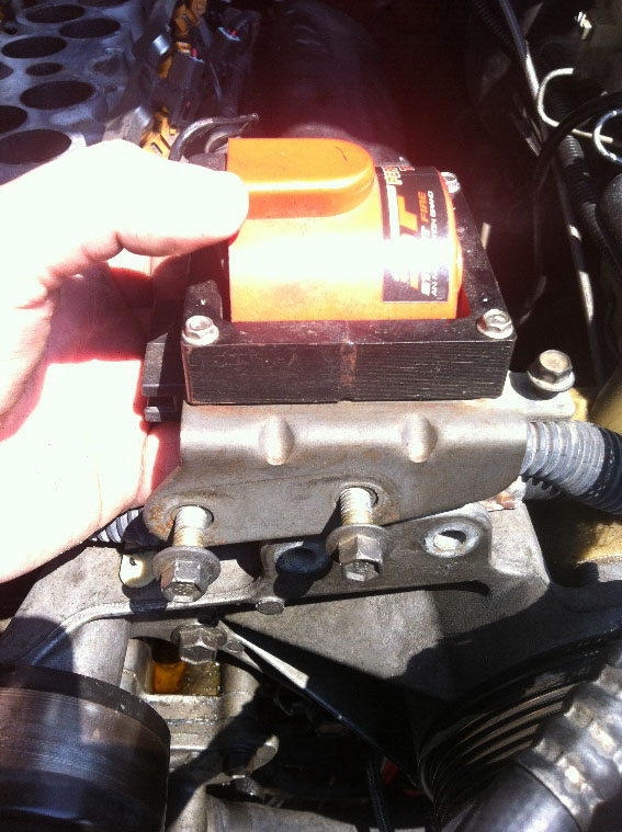
Step 32. Photo 13: Removal of air conditioning line from ignition coil bracket to allow accessory bracket to move forward and away from cylinder head to give more clearance 94-95’ models.
33. Remove the three bolts securing the driver side accessory bracket to the cylinder head. The air conditioning compressor and power steering pump can remain on the accessory bracket and just moved away from the motor for access.
34. With the accessory bracket out of the way, you can now work on cylinder head removal. Remove both valve covers.
35. A decision is to be made at this juncture. If you are going to reuse the pushrods, camshaft and rocker arms, then you need to make sure you keep track of what number cylinder they came from. I was reusing my valvetrain components so I used an old box labeled with each cylinder and intake and exhaust and a piece of paper, and as I removed the rocker arms I placed them on the paper in the correct location stating intake or exhaust. If all new components are being installed then no need. Keep the rocker arm guide tracks if you are installing new pedestal rocker arms, many aftermarket roller rocker kits do not come with the guides and the stock pieces can be re-used. (Photo 14)
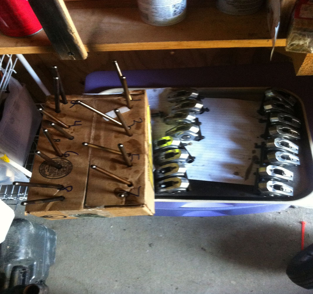
Step 35. Photo 14: Keeping track of location of valvetrain components (if reusing them) to ensure they go back in same locations during reassembly.
36. Begin removing the 10 bolts securing each cylinder head. Removal of exhaust manifolds may be necessary if you cannot get access to the short bolts, but if you can, it is easier to remove the cylinder heads with the exhaust manifolds still on them. Once all are removed, take a rubber mallet and give some taps on the cylinder head in various locations to break its seal. The iron heads are extremely heavy, if you have back problems, injuries or disabilities enlist a friend to help you remove them. (Photo 15)
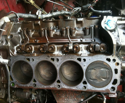
Step 36. Photo 15: both cylinder heads removed. Make sure to save dowel pins and clean them or replace with new.
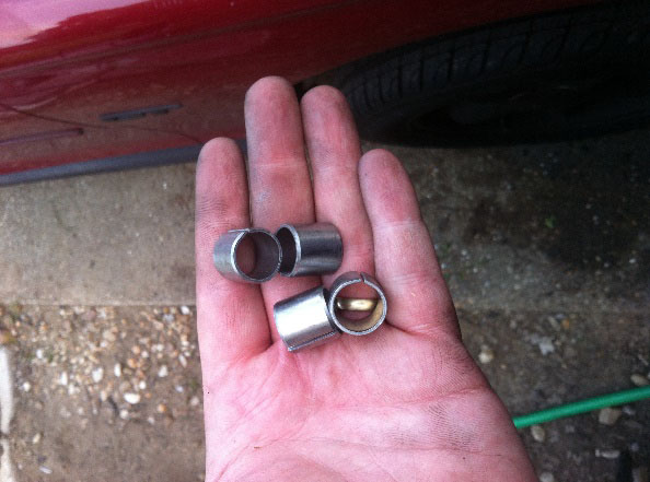
37. Take special care to locate and secure the two cylinder head dowel pins from each cylinder head. Some may remain inside the block while others may stick inside the cylinder head. Set them aside, a new set is highly recommended but the old ones may be cleaned and reused.
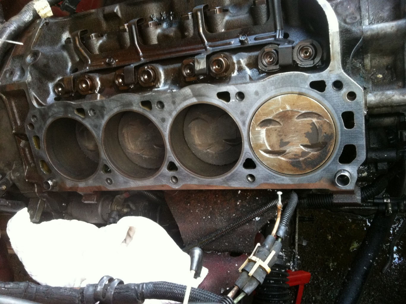
38. Remove the old gasket material. Prep the block surfaces by scraping away all old gasket materials. Use a ruler or perfect straight edge to check block for any warpage. Using a thread cleaning tool, chase all head bolt threads to clean them, use compressed air to clean them out of all debris or dirt. Block deck surface must be immaculate. Test thread new head bolts into bolt holes of block, they should be easy to thread by hand without any feeling of grit or resistance, if you do feel any, clean them again until they do turn smoothly by hand. Dirt throws off torque readings and any fluids trapped in the threads can cause hydro locking that can mean once the fluid boils off the head bolt is not actually torqued at all and will lead to gasket failure.
39. Unboxing and preparing GT40X aluminum cylinder heads. The cylinder heads are universal with accessory bolt holes in the front and back of the heads so there is not left and right cylinder head, but if you are going to be using the factory smog pump you must decide which cylinder head will be driver and passenger side, the fronts of each cylinder head will need the plugs installed with thread sealer. (Photo 16 a,b)
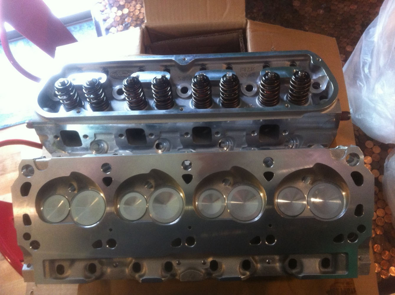
Step 39. Photo 16a: Unboxing New GT40X cylinder heads.
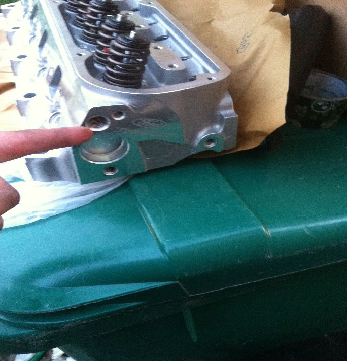
Step 39. Photo 16b: Installing cylinder head plugs in correct side for installation.
40. Remove the exhaust manifolds from the old cylinder heads and clean off all gasket material. Match up your exhaust manifold with the new exhaust gaskets you intend to use to the new GT40X cylinder heads and note the port matching. The exhaust ports of the GT40X heads are much larger than E7TE and many exhaust manifolds and aftermarket headers will need a particular gasket to ensure a leak free seal. The stock exhaust manifolds can be reused if desired and while smaller, they offer ample gasket flange surface to ensure leak free seal with many gaskets on the market. (Photo 17)
41. If exhaust ports match up well, begin installing the exhaust manifolds to your new GT40X cylinder heads, pay particular attention to make sure no cylinder head bolt holes are blocked to prevent being able to install and torque a head bolt down with the exhaust manifold installed. In my case my passenger side header blocked a cylinder head bolt hole location and so I had to install the header after the head was installed. Double check and make sure you installed the manifolds facing the correct direction for what side the cylinder head is going on and that if you have smog equipment that the open holes in the back of the head are facing the correct way. (Photo 17)
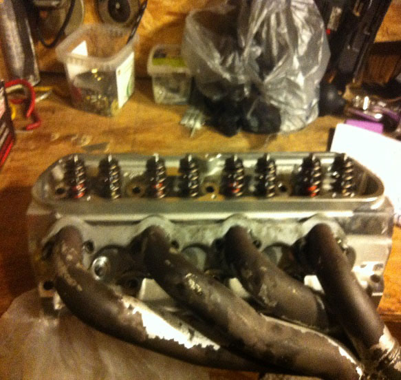
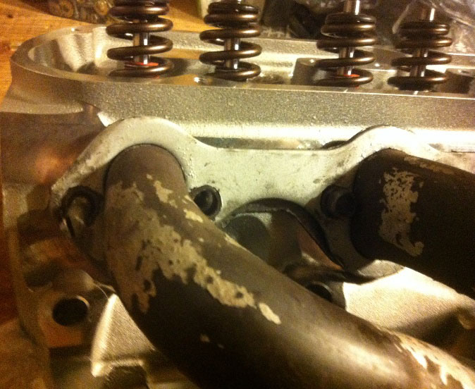
Step 40/41. Photo 17: Pre-installing headers and checking for port matching. Make sure you can access the shorter head bolts before mounting headers, in my case the passenger side I had to install the header after the head was torqued down.
42. Place cylinder head dowel pins into the block and tap them to seat them perfectly flat. (Photo 18)
Step 42. Photo 18: Block surface prepped, holes cleaned, dowel pins in place and tapped flat so they are seated perfectly straight.
43. Lay your new head gaskets down on the block, ensuring the words “front” are both towards the front of the engine. One side is going to be blue side up, one side will be blue side down, this is normal.
44. Get into position with your cylinder head and carefully begin to lower it into place, guiding it down onto the two cylinder head dowels. If the cylinder head does not match up and slide into place on the block smoothly then take the head off and make sure the dowel pins are perfectly flat and clean, then attempt again.
Ford Racing (ARP) 289/302 head bolt kit Item # 50146 and ARP thread sealant (Item # 18221)
45. Once the heads are in place, get your new head bolts and step washers, assembly lube, thread sealer and torque wrench and have them ready. Cylinder heads will be torqued in three stages, beginning with 35 foot lbs so put the torque wrench on that reading if click style in advance. The next several steps are a bit time sensitive because thread sealer is involved and you don’t want it drying as you are torqueing the heads down. (Photo 19)
Step 45. Photo 19: Applying assembly lube to step washer and mounting on cylinder heads.
46. Take each step washer and apply small dab of assembly lube to each and place in the cylinder head bolt holes flat and fully seated. Take your long head bolts and apply tiny dab of assembly lube to threads and underneath each bolt head and thread them by hand, no wrench. (Photo 20)
47. For short bolts that enter water jackets, place dab of thread sealer onto each thread, approximately .25” up from end of bolt and only on threaded part. Apply assembly lube under head of each bolt and thread in by hand, no wrench. (Photo 20)
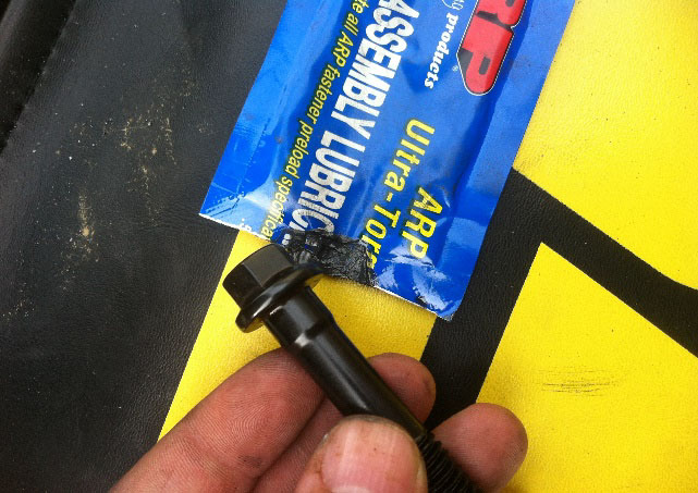
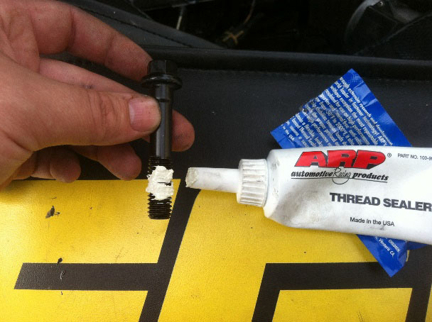
Step 46/47. Photo 20: Preparing head bolts with assembly lube and thread sealer for the short bolts that will be in the water jackets.
48. Taking your torque wrench, torque bolts in proper sequence 35, 50, 70 (all in foot lbs) until first reading achieved for each bolt before moving to next step. (Photo 21)
49. Repeat step 48 for second and third torque sequence until final torque reading of 70 foot lbs is achieved. Go back over again to ensure all 10 bolts achieve 70 foot lbs, if any one bolt does not reach proper torque reading, keep repeating the torque sequence until all 10 are exactly to specs.
50. Move on to next cylinder head and repeat bolt preparation steps 46-49. (Photo 21)
Step 48-50. Photo 21: Proper cylinder head torque sequence. Three equal steps of 35 foot lbs, 50 foot lbs, then final 70 foot lbs.
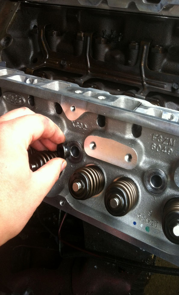
51. Place pushrods back into the cylinder heads, seating them onto each lifter (if reusing old ones).
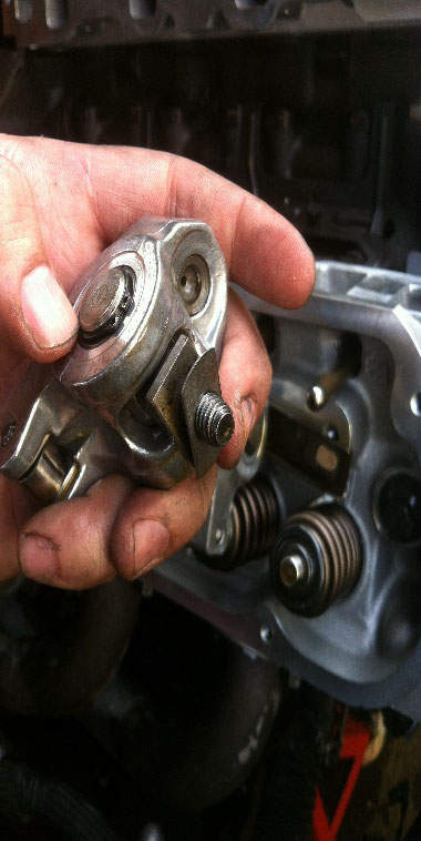
52. Beginning with a cylinder that is on its camshaft base (so both intake and exhaust valves are closed) take rocker arm guide and rocker arms and begin to thread them onto cylinder head. Tighten down rocker arms first to a low reading of around 10 foot lbs and attempt to roll the pushrod between your fingers, if it’s too loose examine the lifter first, it should be pumped up and firm, if it is not them you may have a collapsed lifter. Assuming all lifters are in good repair, the pushrod should barely be able to spin. Also take note of the placement of the rocker arm tip on top of the valve stem, it should be centered on top of the valve tip, not too far in front of it or behind it, if this occurs you may need to shim your rockers. (Photo 22)
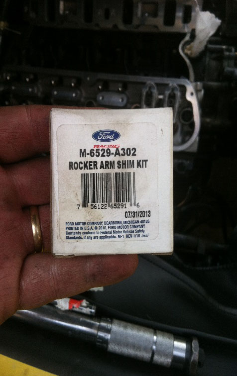
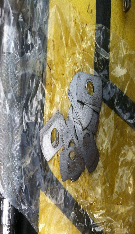
Step 52. Photo 22: Ford Racing M-6529-A302 for all pedestal rockers, Item # 50310.
53. Using 1” socket and a breaker bar, rotate the crankshaft pulley to turn the motor over until each cylinder you are working on it on the camshaft base (both intake and exhaust valve closed, you can see in the lifter valley that both lifters are equal and at their lowest point. Install all pushrods and rocker arms, torque to 20 foot lbs. Rotate motor over with all valvetrain in place and make sure every pushrod is barely able to be rolled between your fingers, none should be loose at all, and make sure that you witness the tip of each rocker contacting the valve tip as it opens the valve to ensure the tip is centered on the valve tip during the entire opening and closing of the valves.
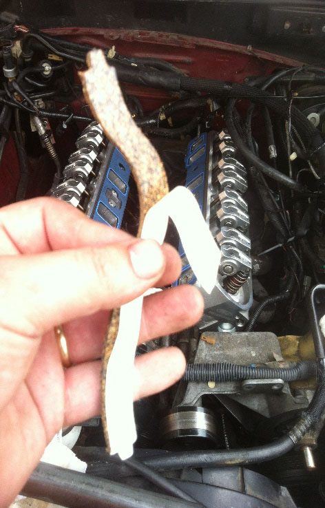
54. Clean up your old lower intake manifold and make sure it is immaculate. Often times, corrosion occurs around the coolant passages. A dab of RTV ultra gray works well, super lightly coat the area around coolant passages when ready to install.
55. Take four old intake manifold bolts and cut the heads off of them and grind a mark in top of each so a screwdriver can screw them, these will be very handy for installing intakes now and in the future. (Photo 23)
Step 55. Photo 23: An old intake bolt with head cut off and a slit grinded into it makes a great stud to not only help hold intake gaskets in place but to guide the intake down over it and make the job much easier. The slit in the tip is to be able to take a screwdriver and remove them easily when done with them.
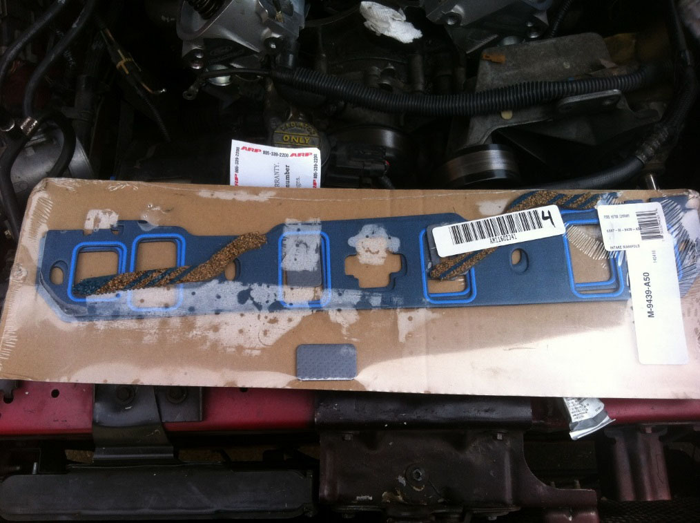
Ford Racing intake gasket set M-9439-A50, Item # 50265. For applications that do not have EGR you can use the provided gasket inserts to block the EGR holes in the cylinder heads.
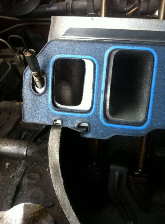
56. As discussed in Parts Required section, make sure you test fit your new intake manifold gaskets to your intake on the head and shine a light down into the intake ports to check port alignment. If the intake sits too high up or too low then the intake gaskets will likely leak, I used an Explorer intake with the recommended Ford Racing intake manifold gasket kit #50265 (Ford Racing part number M-9439-A50). (Photo 24)
Step 56. Photo 24: Always check port alignment of your gaskets between the cylinder head and intake.
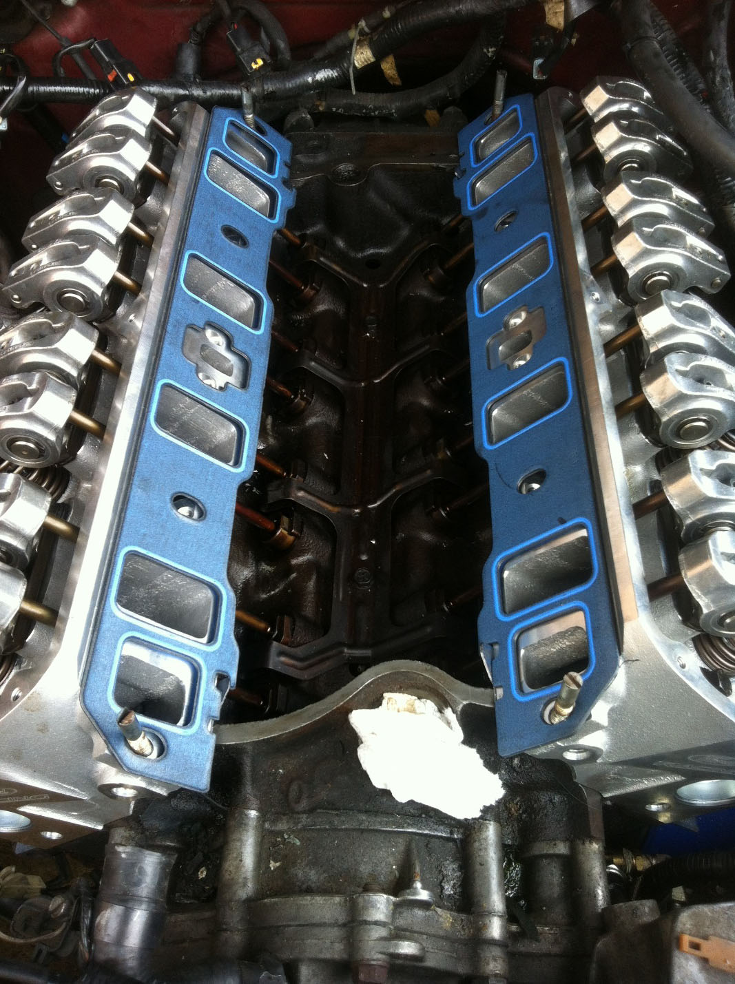
57. If port alignment matches, place the four cut intake bolts into the heads and slip the intake manifold gaskets into place. The supplied cork gaskets have tape on them so remove the backing and lay them in place. Put a dab or RTV in the corners of the gaskets where it meets the cylinder heads. Use a gasket sealant or light coat of RTV over the cork gaskets. (Photo 25)
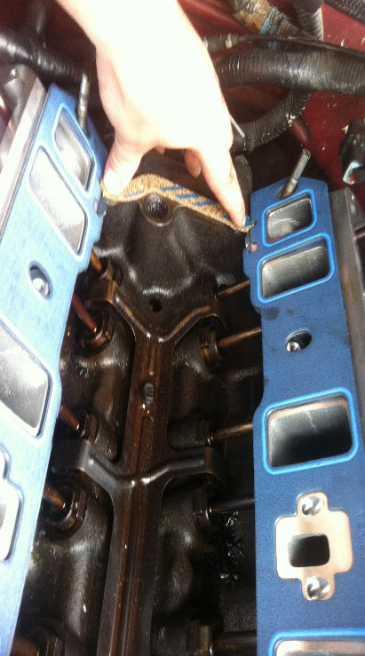
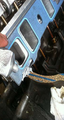
Step 57. Photo 25: Applying cork gaskets and putting RTV silicone in corner of each. It is also perfectly acceptable to just use RTV by itself if desired.
58. Place your lower intake manifold into place, the cut intake bolts will act as guides to hold the gasket in place while the intake is lowered down. Once in place, take your new intake manifold bolts and begin to thread by hand. I put a small dab of assembly lube to the threads of each bolt, some prefer anti seize and others nothing at all which is all fine. Thread all bolts down by hand.
59. The intake manifold will be torqued in three steps. Following Photo 26 you can see the torque sequence. First step will be 96 inch lbs. Second step will be 10 foot lbs. Third and final step will be 20 foot lbs. Do not move on to each torque sequence until torque reading is reached, it does not matter how many times you must go over the sequence. I had to go over my intake for the final 20 foot lbs about 5 times before every bolt read the correct amount of torque. I highly recommend you walk away for 24 hours before coming back and starting the engine. This gives plenty of time for any RTV or gasket sealants to set and gaskets to compress. I came back the next day and re-torqued the intake manifold and needed to go over it another 3 or 4 times before all the bolts reached specs. (Photo 26)
Step 59. Photo 26: Intake manifold torque sequence. I had to go over my intake on the last step about 5 times to get 20 foot lbs. It is highly recommended when done with this step to wait one full day before starting so all RTV sealant dries and gaskets compress, then retorque again to 20 foot lbs.
60. With the intake now in place, reassembling the motor is the reverse steps 34 through 1. Pay particular attention to when you reinstall the power steering pulley as not to damage it, make sure it goes on straight, use the correct installation tool (Step 31).
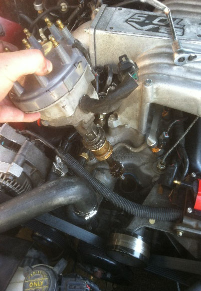
61. Reinstalling the Distributor. It is a good idea to prime the motor before installing the distributor if you have the correct priming tool and an electric drill. You had to rotate the engine over several times, therefore you must locate cylinder number 1’s top dead center. Remove cylinder number 1 spark plug and while turning over engine with 1” socket on a breaker bar feel the spark plug for when air begins to escape, you should feel it on your finger in the spark plug hole as well as hear the noise it is making. Soon as the air stops escaping the cylinder is approaching the top, so then all you have to do is shine a light on your vibration dampener and rotate the motor until it reads zero on your timing marks, you are now at top dead center and can install the distributor with the rotor facing the number 1 on the distributor cap, or your own timing marks if you marked where the number 1 cylinder is on the inside of the distributor.
62. Installing spark plugs. On aluminum cylinder heads use small amount of anti-seize on the plug threads. The GT40X calls for AGSF-32C or equivalent with a gap of .052”, you may use tapered or gasketed plugs. I used NGK V-power T-R5. Do not over tighten, NGK called for 15-17 foot lbs on aluminum heads. (Photo 27)
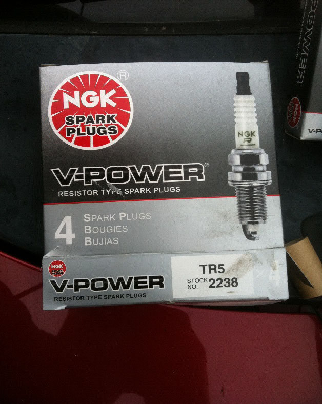
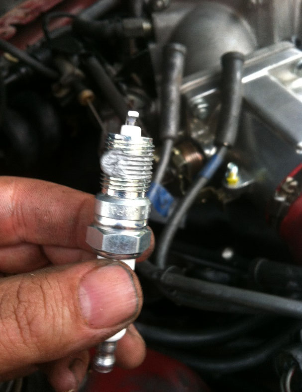
Step 62. Photo 27: Ford Racing GT40X heads call for AGSF-32C or equivalent spark plugs. I used NGK TR-55 Item # 64021 from American Muscle. Don’t forget to check the gap, and put a dab of anti-seize on the threads. My plug gap is set to .052” for normally aspirated.
63. Topping off coolant. I prefer to use the burp method to remove any air from the block and lines. If you start the car and immediately the temp gauge goes up to hot then likely an air pocket is trapped inside the heads or the intake.
64. Before starting the car for the first time, unplug the PIP spout connector located by the passenger fender by the ignition control module (or on distributor of fox bodies). Prepare your timing light and have distributor wrench ready. Start the car and check base timing, place on 10* BTDC (stock setting). Turn off engine and reinstall PIP connector and start engine again.
65. Change your oil immediately after everything is reassembled, inevitably coolant will get into the oil. Have an extra oil change kit ready to go for after driving several days to recheck for leaks as a follow up (coolant leaking into the oil). After car has been driven some time, also check the coolant for signs of oil mixing. Pay particular attention to coolant and oil levels.
66. I drove for a few days, then pulled off the upper plenum one more time and retorqued lower intake back to 20lbs and retightened exhaust manifold bolts and double checked all hose clamps and rechecked base timing.
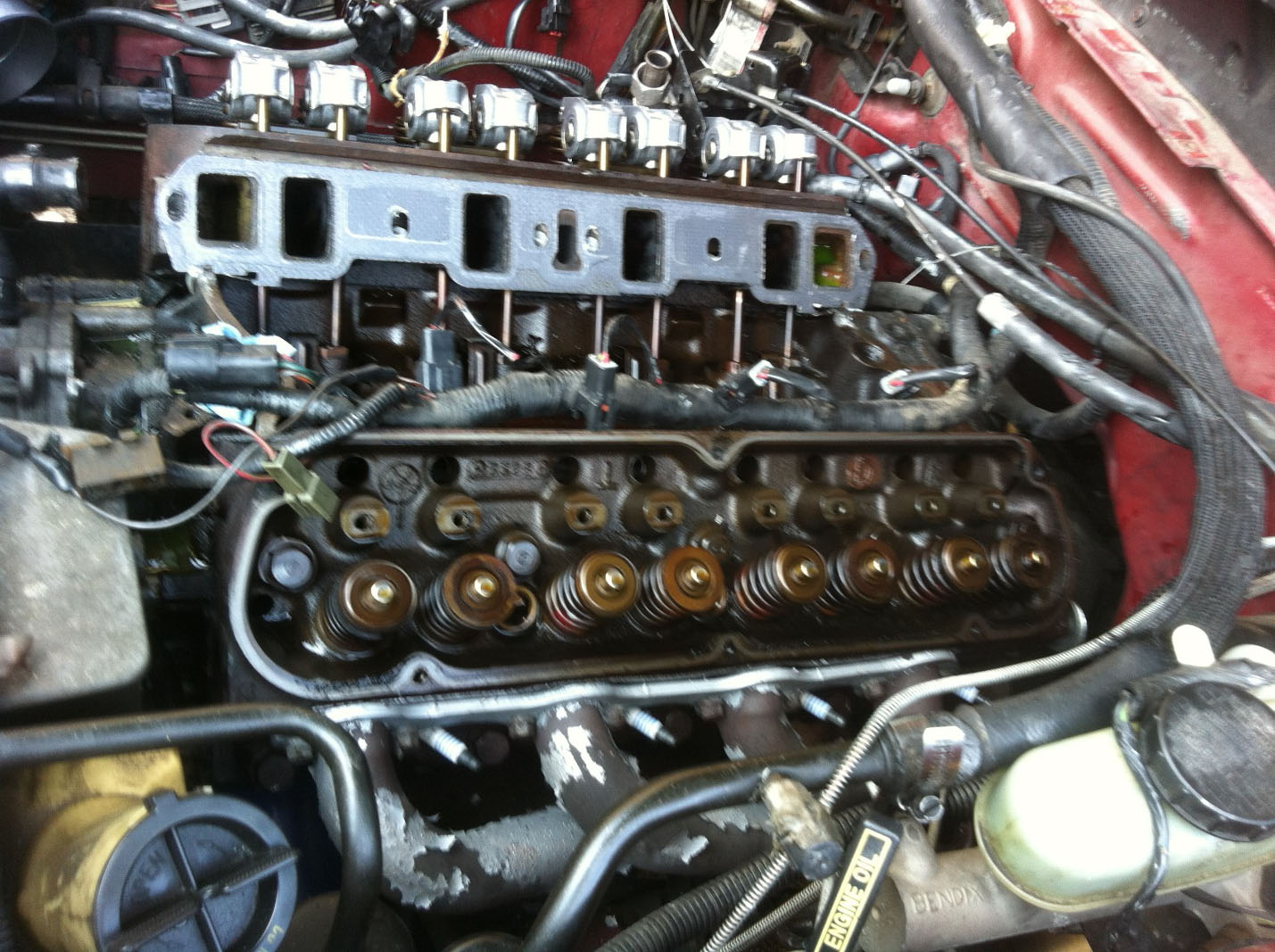
BEFORE
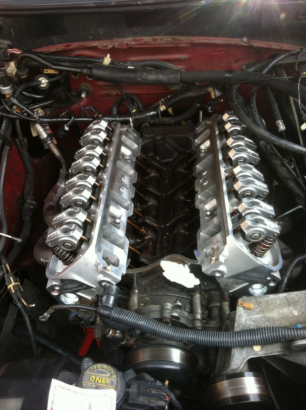
AFTER
Installation Instructions written by AmericanMuscle Customer Edward McSwain 8.20.2014