FREE 1 to 3-Day Delivery on Orders $149+ Details
How to Install a JLT Performance Next Generation Cold Air Intake on a 2003-2004 Mach 1 Mustang
Installation Time
1 hours
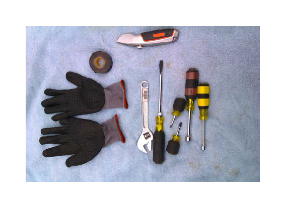
Tools Required
- 5/16” and 7/16 nut drivers
- Flat bladed screwdriver
- Towel or fender work mat to protect paint
- Small adjustable wrench
- Stubby (short) Philips and flat bladed screwdrivers
- Gloves
- Box knife
- Electrical tape (3M's Super 33+ or equivalent)
- Flashlight (not pictured)
- Simple Green or equivalent cleaner (not pictured)
- Towels or rags (not pictured)
- Car jack and jack stands (not pictured)

Shop Parts in this Guide
Note: While one can probably get away with only using a stubby Philips throughout this installation, it's just as well to have the preceding tools, as they will help to make it quick and clean from start to finish. While the guide recommends a jack and jack stands, you can do it without, just be prepared for considerably less room to work with.
Installation Instructions:
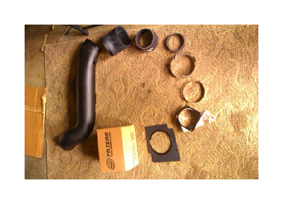
1. Open up the box and verify all of the components are accounted for.
In order, clockwise, starting with the tube:
- JLT tube with PVC fitting
- 45-degree rubber throttle body elbow
- 4.5”-4” silicone reducer
- Silicone spacer
- #72 clamps (3)
- #64 clamps (1)
- MAF adapter and gasket, with bolts (4)
- Apron plate
- SB 4x6 air filter
1. If you are not very experienced with working with wires, please disconnect the battery from the terminals, and prevent yourself from coming to harm. You will have to use a box knife to remove some of the covering on the main harness to peel back your wires for your mass air flow (MAF) sensor.
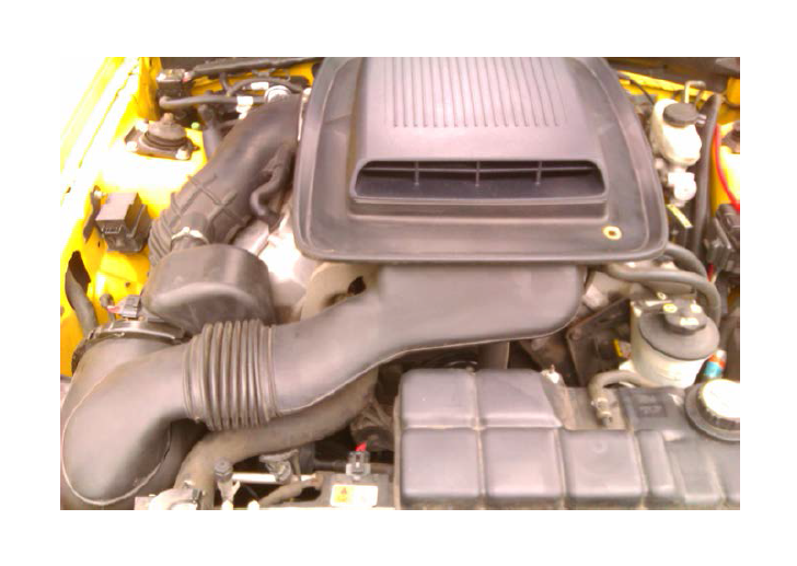
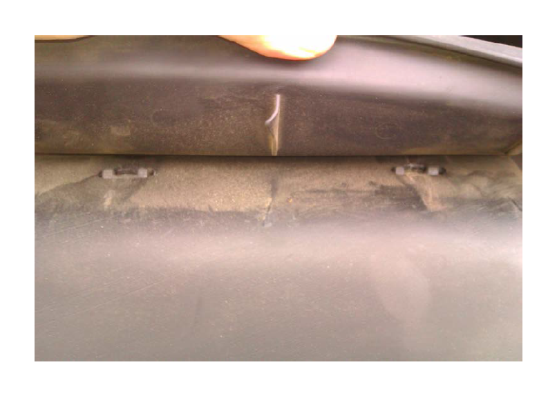
2. If you peel back the rubber water gutter on the shaker, you can see the clips for the shaker system hose on there. Take a large, flat bladed screwdriver, and pry the hose off the top two. Afterward, a firm pull up and towards you will remove that hose.
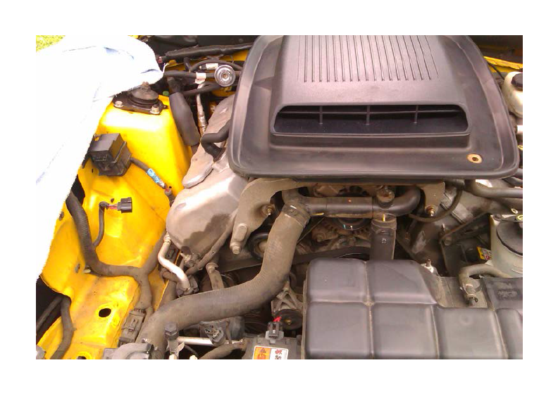
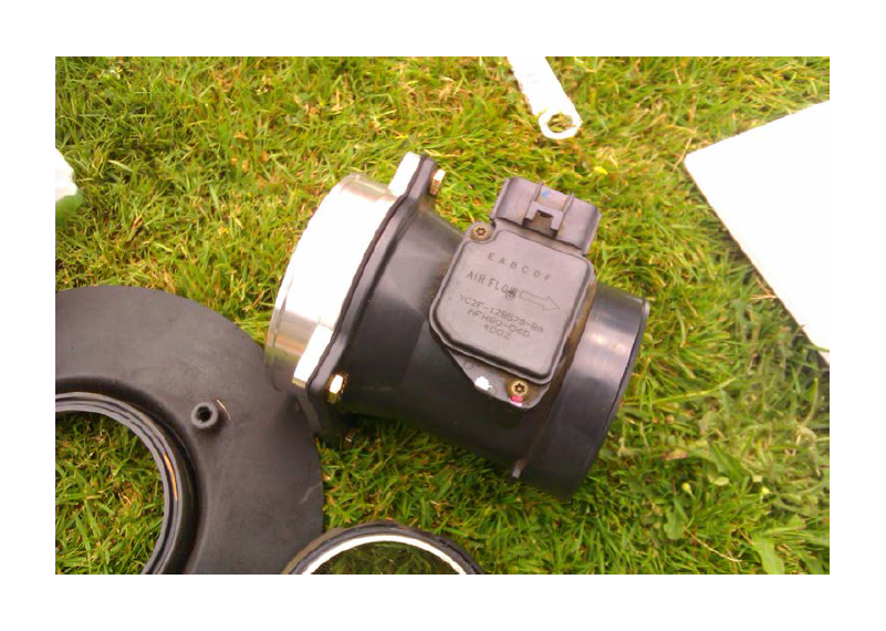
3. On both the throttle body and MAF sensor clamps, they have retaining tabs. You should be able to loosen the hose clamps and slide them across to the retaining tabs, and pull it right out. There is a small re-up hose that emerges from the valve cover, you leave it on, or pull it off and save it for later. You will need this item for re-installation.
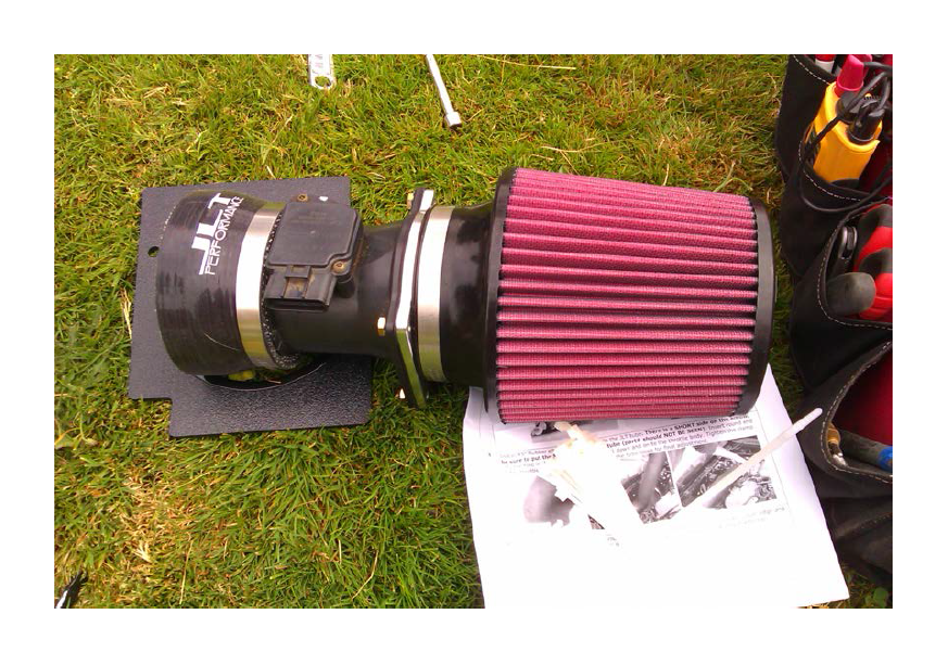
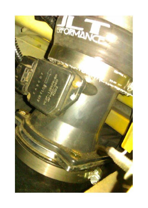
4. Unbolt the MAF from the air filter housing, and bolt it onto the new MAF housing using the gasket that came with your CAI kit (7/16” nut driver). Attach the silicone spacer and silicone reducer on one end, and the air filter on the end with the new MAF housing, with the supplied hose clamps. Do not re use the screen or bolts that came with your stock kit.
5. Slide the silicone reducer onto the other end of the MAF sensor, and, over that, slide your silicone reducer with the smaller hose clamp (#64) on one end, and the larger hose clamp (#72) on the end that will attach to the tube. Make sure the reducer is seated against the smaller tabs, and the reducer is seated against the large tab.It is also important to note not to over tighten the clamps, as this may cause them to break, or the head on the clamp to warp. They only need to be tightened until snug. Use your fingers to squeeze around the hose clamp and ensure proper seating. Your assembly should look like the picture below:
6. Note: While these components aren't installed, you may want to take the time to use the simple green and some rags to clean out the engine bay. There are areas exposed that weren't before, so a little fluff and buff doesn't hurt. I also took the time to clean my MAF housing during this step.
7. Using a box knife, carefully cut the tape on the harness back to where the harness emerges from the cutout in the engine bay. Once this is done, place the MAF wiring plug through the previously mentioned cutout for later installation
8. Use the plastic conduit (the ribbed covering) to peel away the covering without doing significant damage to the wires. Take great care not to knick any of the wires with your knife. Doing so may cause major headaches down the line. Once you have peeled back the wires, use the electrical tape and wrap everything up nice and neat. This will help to keep moisture and such away from your wires, which is also important, since your MAF sensor will be relocated to the fender well.
9. Install the apron, using the stock air filter bolt (5/16” nut driver) Before attaching the apron, create an edge guard around this hole with some tape. This will aid in reducing any scratching that may occur while installing the pipe.
10. Install the 45-degree elbow and clamps onto the tube. Make sure the short end of the elbow is attached to the tube. When installing the elbow, the part number will be on the underside when it is properly in place.
11. If you find yourself having trouble attaching the elbow to the tube and/or throttle body with the clamps attached, you may also loosen the clamps to the point where they become disconnected. After the elbow and tube are properly connected, pinch the ends of the clamp together with one hand, while you tighten the nut with the other hand. Do not tighten the clamp yet, as you will need to adjust the tube at times to get your MAF and air filter to fit properly.
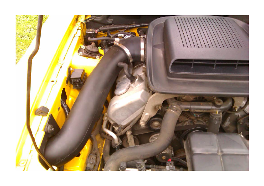
12. Once the tube and elbow have been attached, attach the assembly to the throttle body. To properly put the tube in place, first place the round end into the apron hole with the assembly upright, and rotating it towards the end of the engine bay. Once you are able to seat the elbow, tighten the clamps to a snug fit. Again, use your fingers to ensure a proper seating all the way around. Failure to do so will result in air leaks.
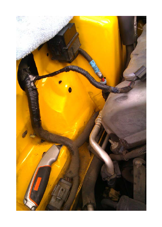
13. Access the fender well by removing the Philips screw with a stubby screwdriver and two push pins, and pulling the plastic shield back. Don't be afraid to muscle this around a bit, it's a sturdy piece designed to hold up to years upon years of wear and tear. Also, be advised: If you've never accessed your fender wells, there will be a litany of crud and dirt to greet you. At this time, you may wish to spend an extra minute cleaning some of this off, thus keeping it from getting into your MAF housing and air filter during installation.
14. Install the MAF/air filter assembly onto the round end of the tube. Rotate the tube at the throttle body, to the right or the left, to help make adjustments during this time.
15. Keep in mind the MAF plug should be pointed towards the driver's side. Not doing so will almost certainly guarantee your wires will not reach your assembly.
16. It is also noted to make sure that all of your clamp's nuts be located so that they face towards the rear of the vehicle, in an accessible spot for tools. This will help in the future, should you need to remove any of the components for maintenance or cleaning.
17. If you find yourself having problems with length on the wires, you may try to rotate the harness so that your wires are facing down, or give a firm tug on your MAF wires themselves. However, do not pull these wires by the plug itself, as this may cause wires to pop out of the plug.
18. Close up the fender well, and snugly tighten the clamp on the elbow, re-attach the re-up hose, and your installation is finished!