 FREE 1 to 3-Day Delivery on Orders $149+ Details
How To Install J&M Rear Lower Control Arms - Street/Race for your 1999-2004 GT, V6, Mach 1 Mustang
Installation Time
3 hours
Tools Required
- Floor jack
- 2 jack stands
- Ratchet
- 15mm socket
- 18mm socket
- 13/16” socket
- Torque wrench (optional)
- 4 bricks to chalk tires
- Metal cutting tool (such as a Dremel)
- Small scribe or flathead screwdriver

Shop Parts in this Guide
Removal Procedure:
1. Chalk front tires by placing one brick (or other object) both in front of and behind each of the front tires.
2. Loosen the lug nuts on both rear wheels.
3. Using the floor jack, raise and secure the vehicle onto the two jack stands, placing them under the rear axle so the rear suspension is nearly under normal load.
4. Finish removing lug nuts and take off rear wheels.
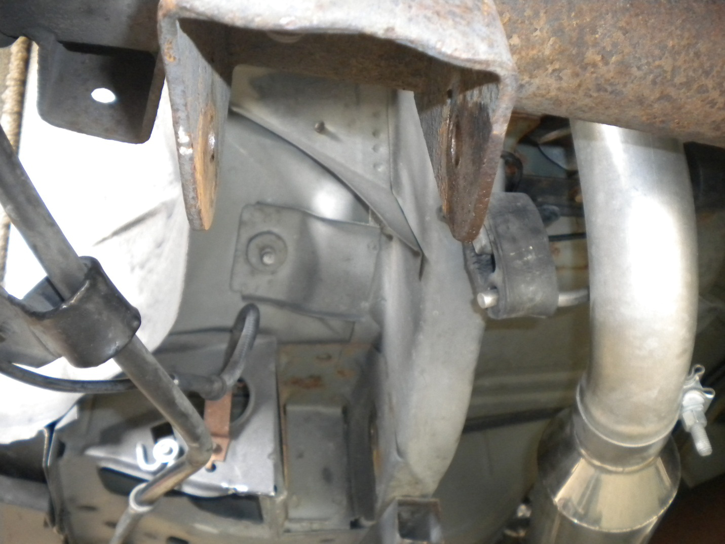
5. Once vehicle is properly raised, locate rear sway bar under rear of car.
6. Remove ABS sensor line from its respective bracket on each side by lifting up on the ABS sensor line with your thumb. This may be stuck in the bracket pretty well so it may take some coaxing.
7. Loosen and remove the (4) 15mm bolts that secure sway bar to rear lower control arms using ratchet and 15mm socket. Remove sway bar.
8. Now locate the nut and bolt securing the rear of the lower control arm to the axle. The bolt will require a 13/16” wrench or socket, and the nut will require an 18mm socket or wrench.
9. Working on one side at the time, place floor jack under the bottom of the lower control arm, and lift only enough to give it a slight load.
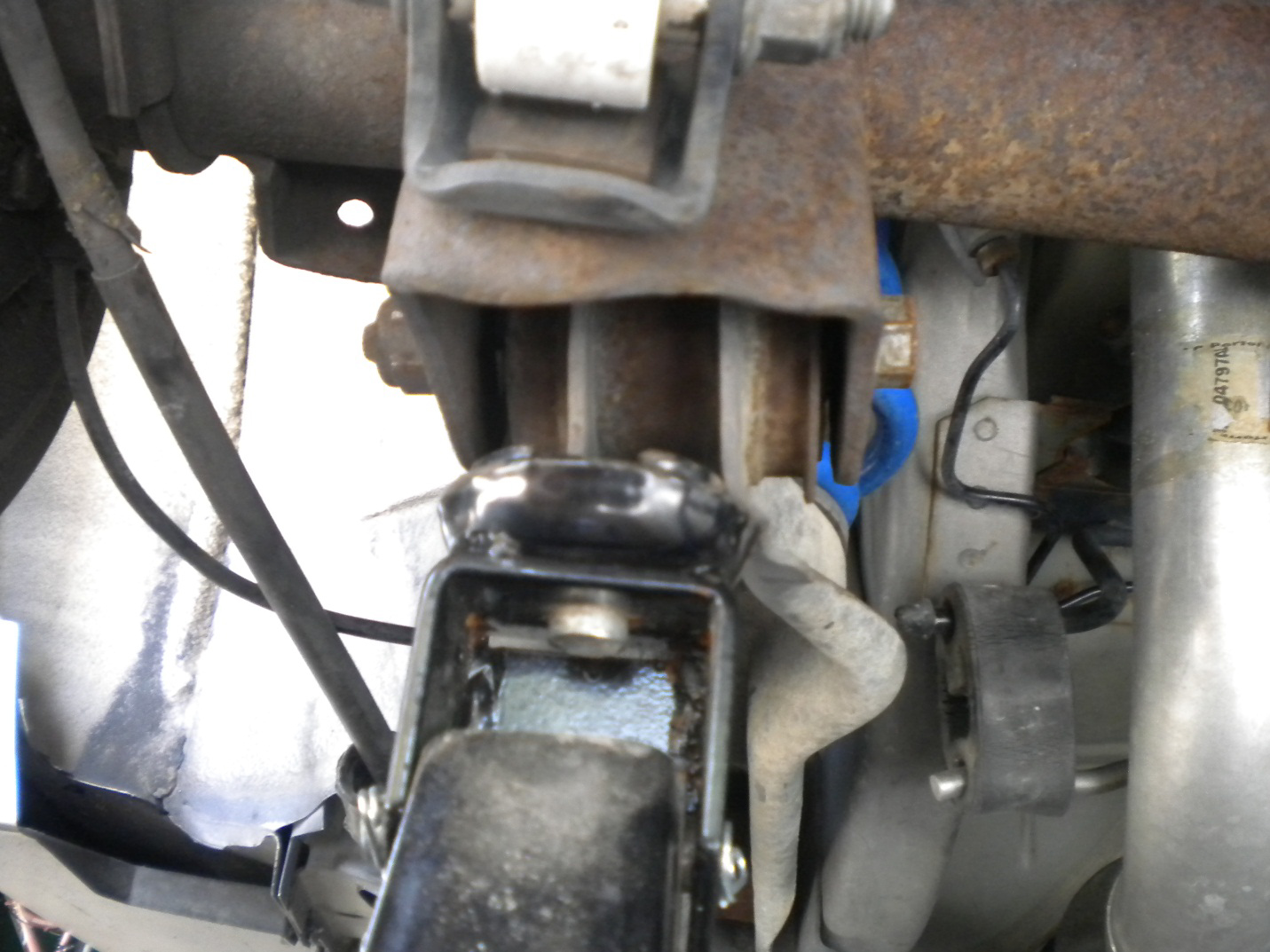
10. Loosen and remove this hardware WITH the rear of the lower control arm being supported by the floor jack. Keep in mind this control arm is also under load by the rear spring. Once the hardware is out, carefully and slowly lower the floor jack and remove the rear spring. This step is the most tedious. Also note that as these vehicles become older, the bolts and bushing will sometimes for a very strong bond and will resist being removed easily. I experienced great difficulty removing the bolt from the rear of the left lower control arm, and was forced to use a C-clamp to push the bolt out, due to the bushing resisting the displacement of the bolt.
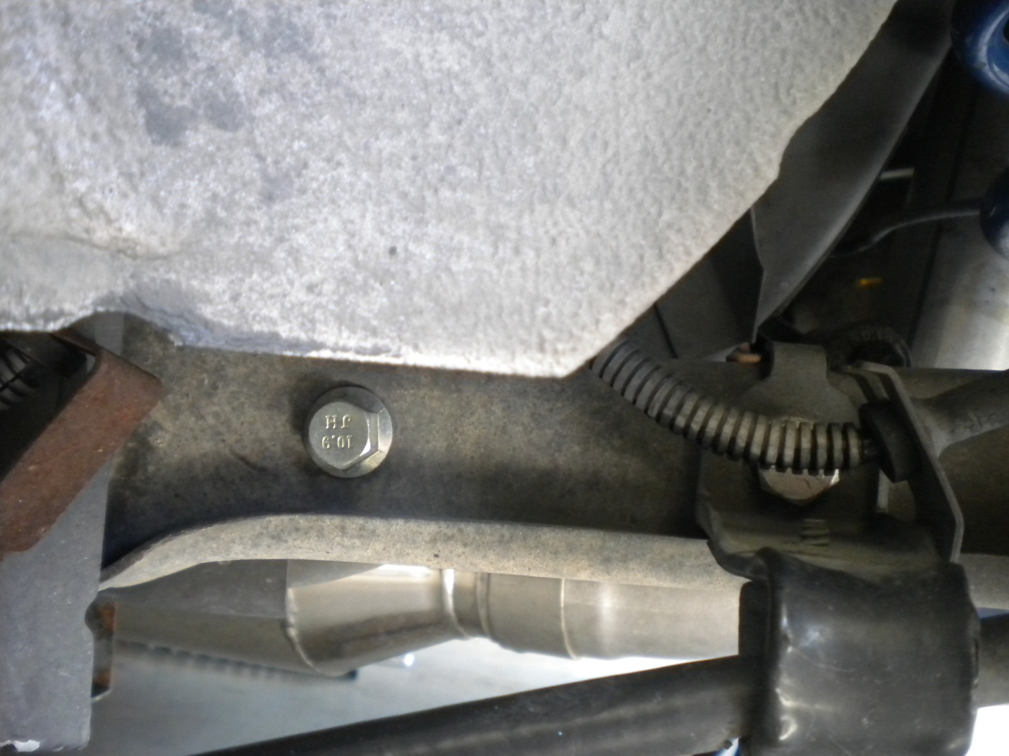
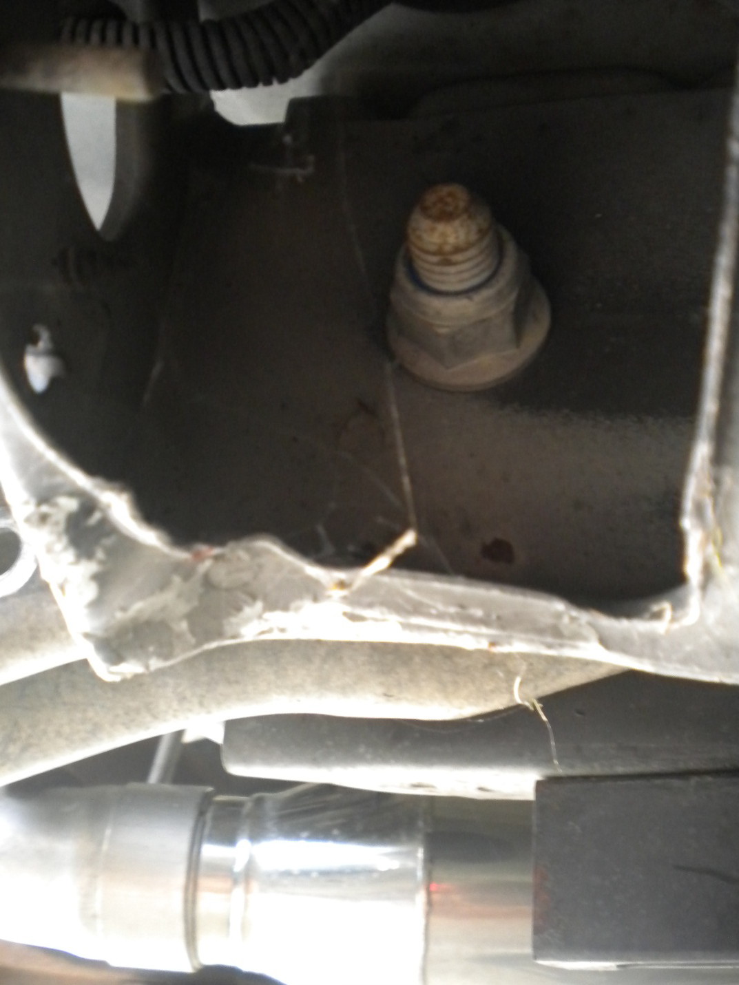
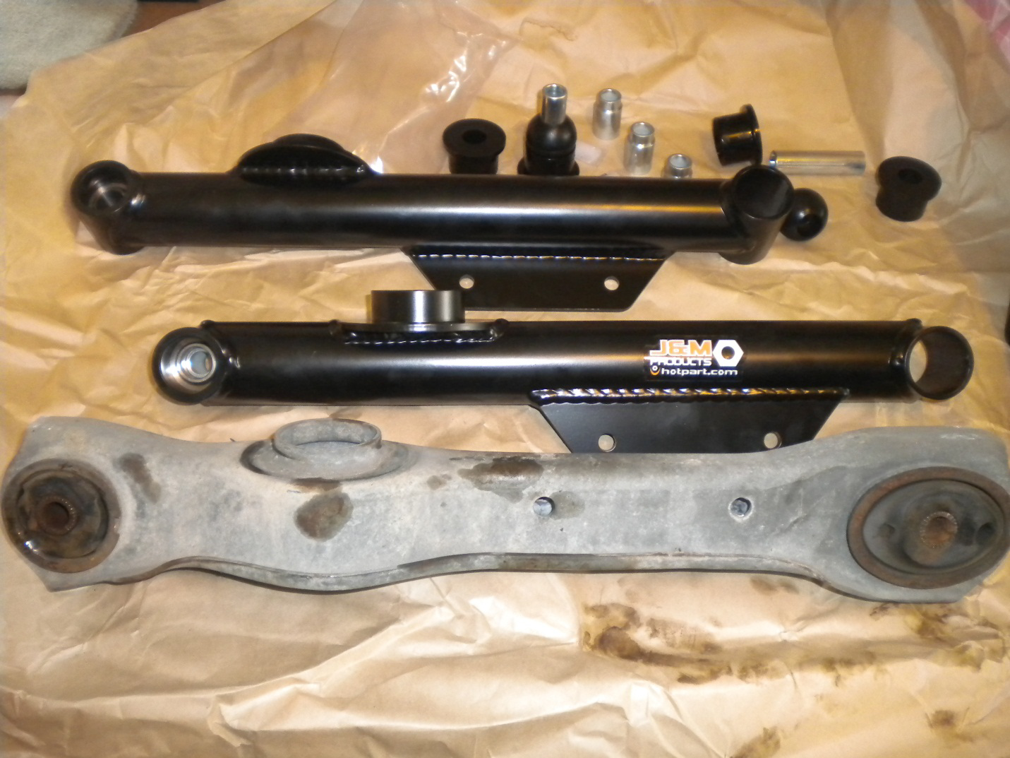
11. Now locate the nut and bolt at the front of the control arm, where is mechanically connected to the chassis. Again the bolt head is 13/16” and nut is 18mm. With this hardware removed, pull out the factory control arm.
Installation Procedure:
12. It is time to install the bushings in the new lower control arms. Use as much grease as possible when putting these bushings together to prevent premature wear and unwanted noise.
Note that a common issue when installing the poly bushing is that they will not completely come together in the LCA. This is because air is trapped inside the bushing when they are put together. This internal pressure may be alleviated by pushing a SMALL scribe or flathead screw driver down in the bushing to let the air out. Emphasis on using a small instrument so the bushings are not harmed when attempting to release the trapped air.
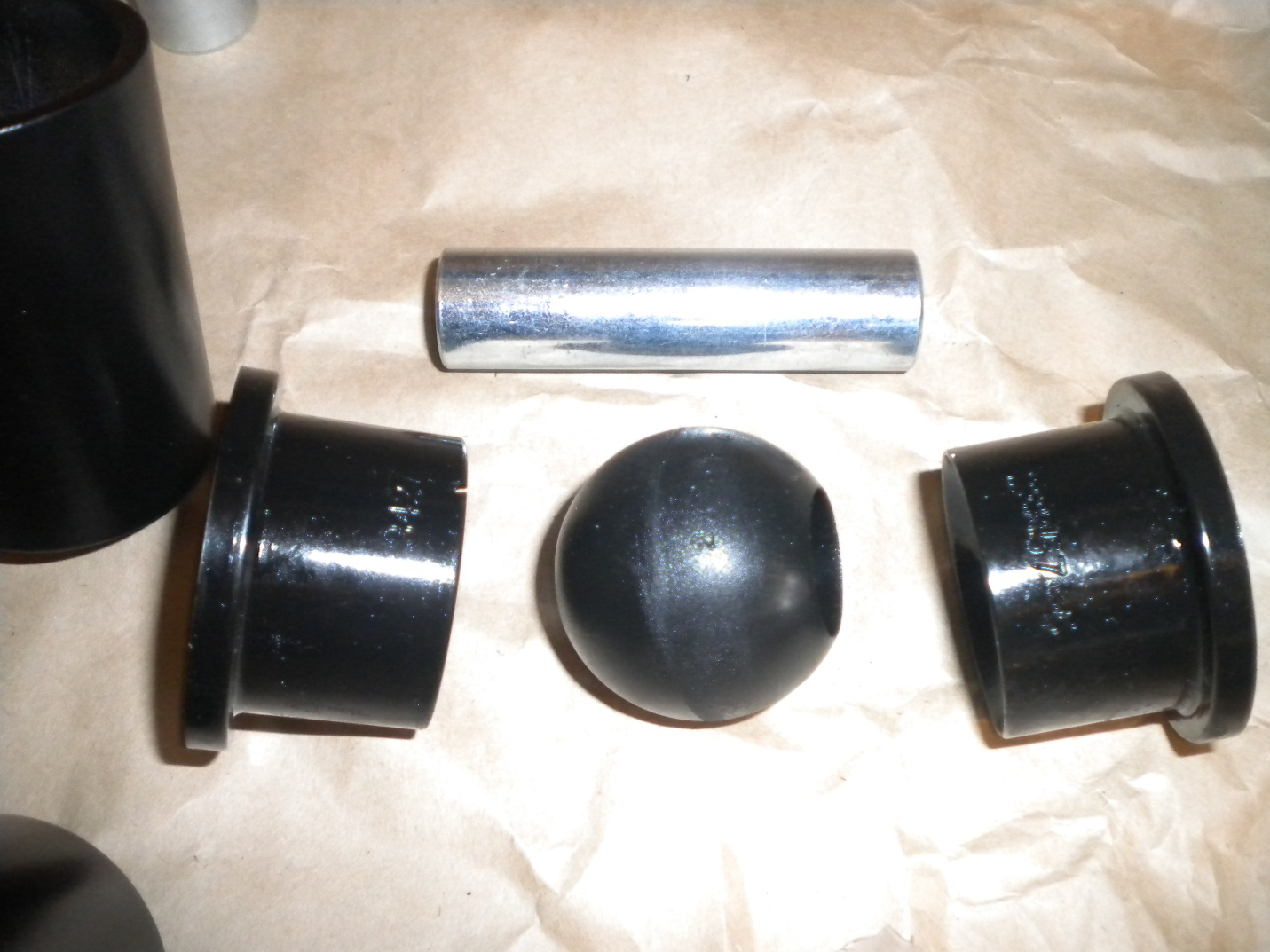
Shown is the poly bushing sequence used for the “front” or chassis side of the LCA. Use a liberal amount of grease when installing these in the control arm.
Chassis side of LCA with poly bushing installed.
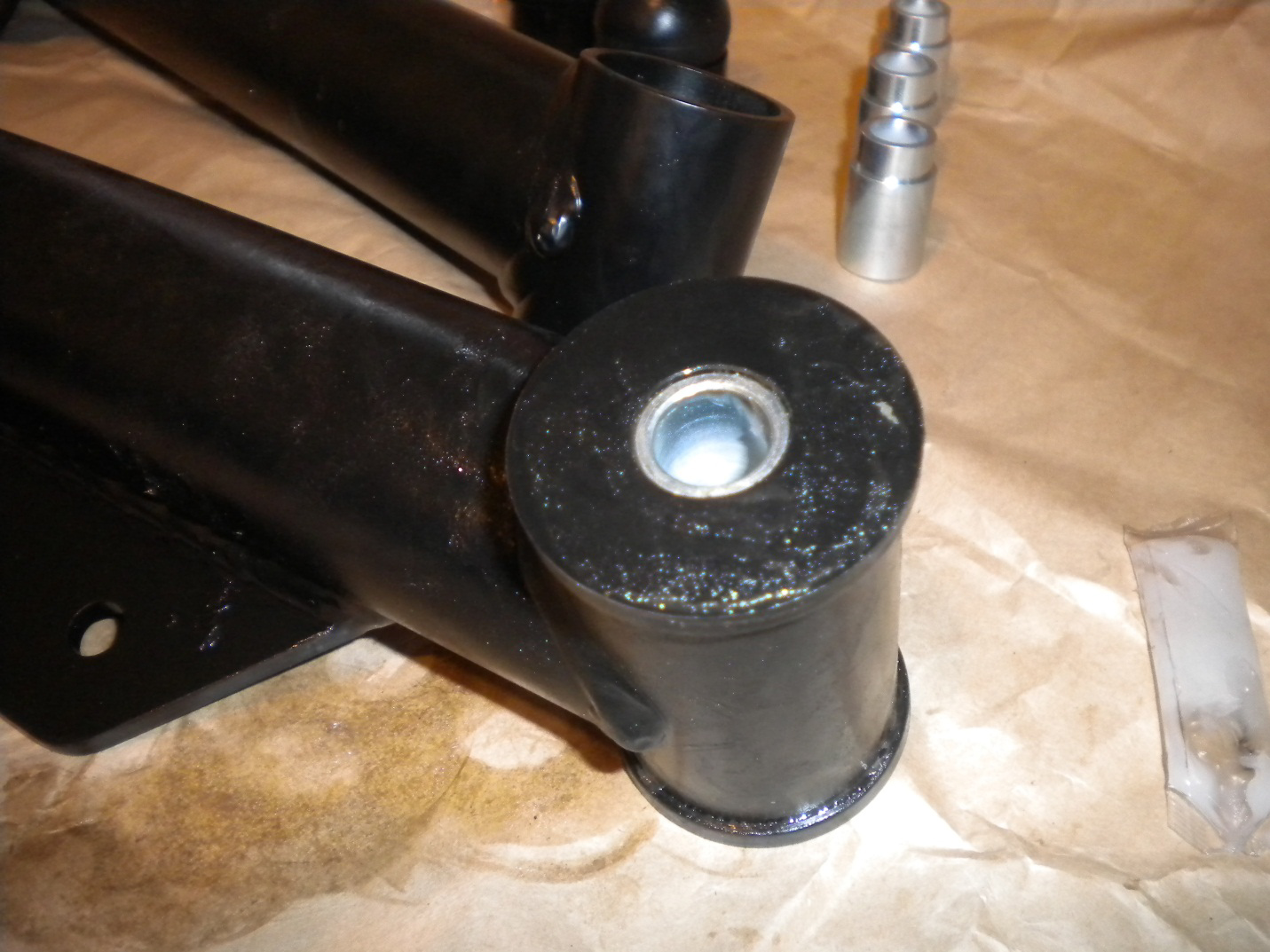
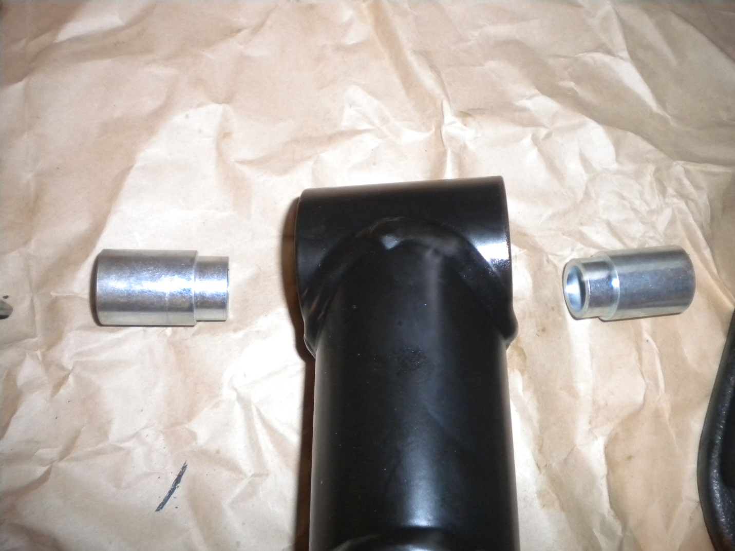
“Rear” or axle side of LCA with spherical bushing sequence shown. Simply grease all contact points and push these metal bushings into the metal bushing that came pressed into the control arm.
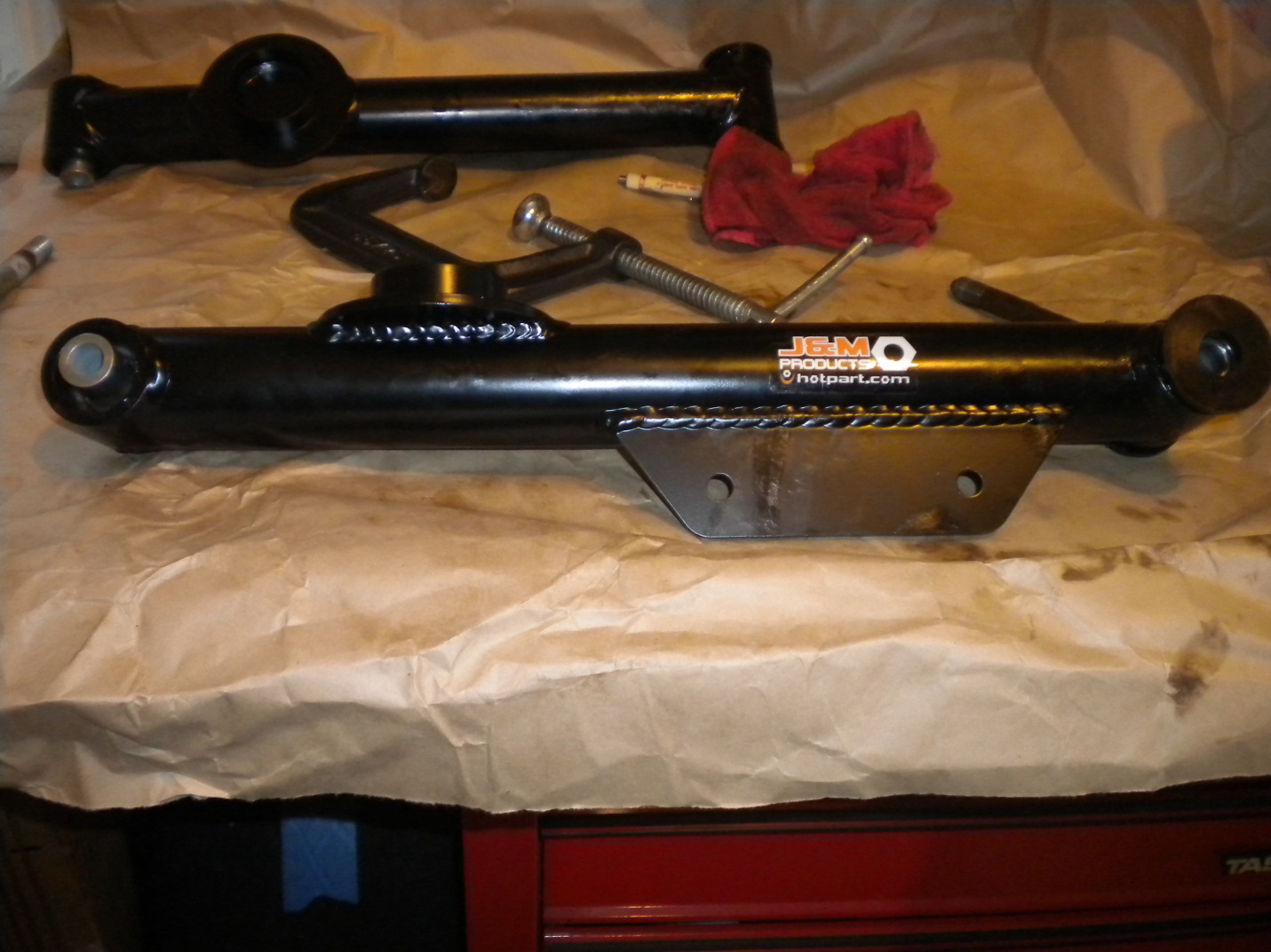
Passenger’s side LCA with all bushings installed.
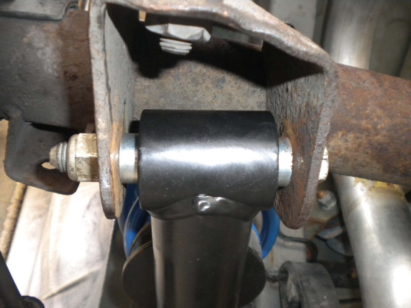
13. With bushing adequately greased and properly installed, begin installing the new LCAs by aligning the front or chassis side of the LCA with its appropriate hole in the torque box. This may be difficult because the new bushings will present a tight fit, but with some coaxing it can be done. Torque pivot bolt to 111 ft*lbs if you have a torque wrench.
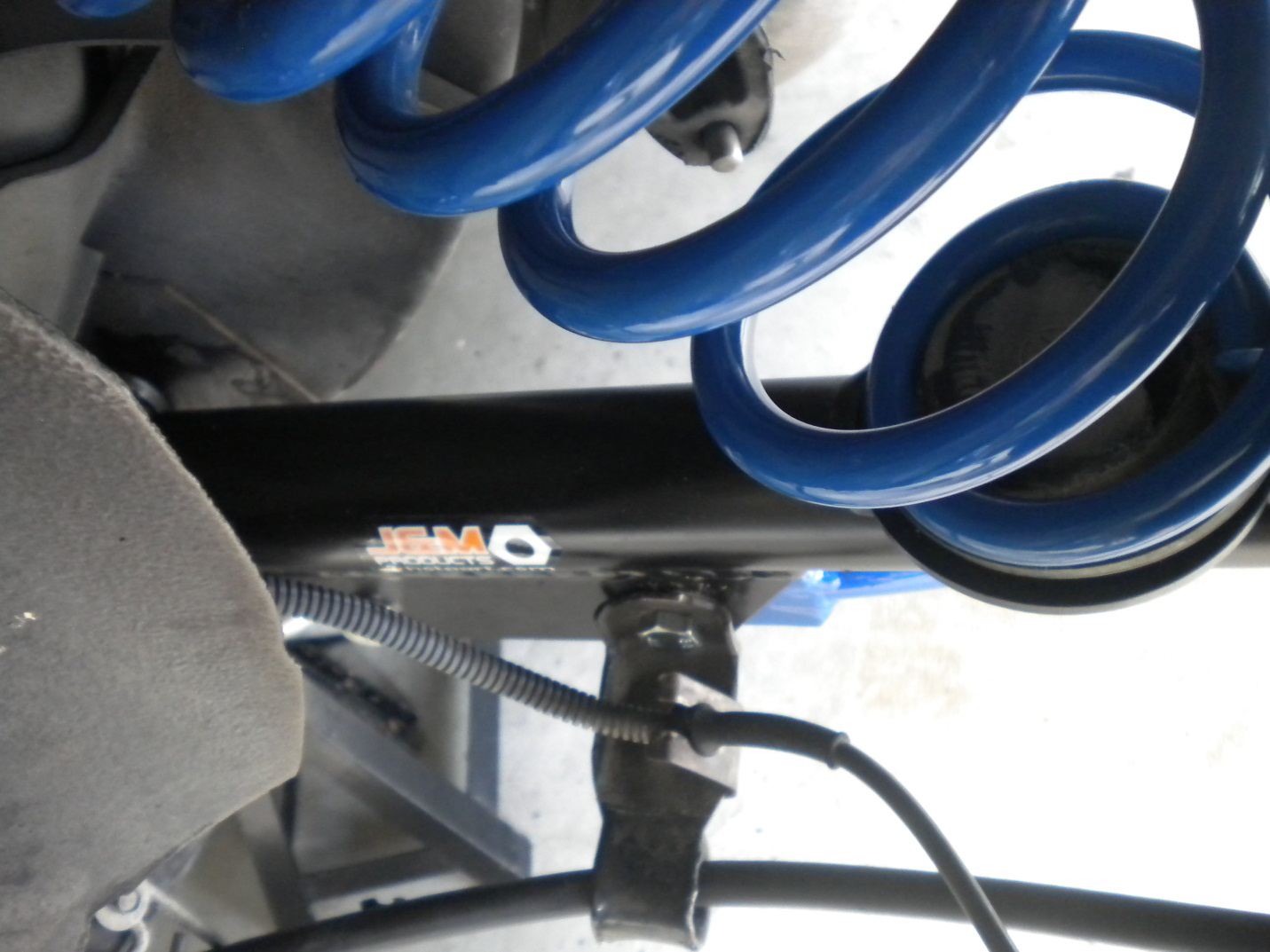
14. Now recover the spring isolator from your factory lower control arm (or new isolator if you chose to replace) and place it on the spring perch of the new LCA. Now place the spring on and be careful to orient the lower pigtail of the spring so that it points toward the left or towards the driver’s side of the vehicle. Use the floor jack to carefully raise the control arm. Be sure to put the top of the spring in its appropriate location in the chassis. Put the bolt through the mount on the axle and through the spherical bushing on the control arm. Torque this pivot bolt to 111 ft*lbs.
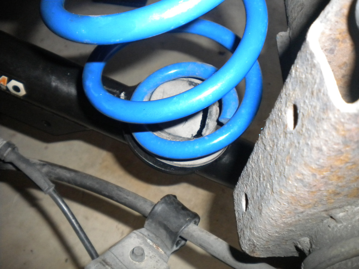
Pigtail of spring facing outward to the left side of car. It should be oriented the same way on both of the LCAs.
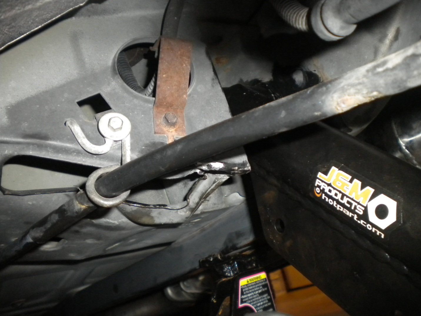
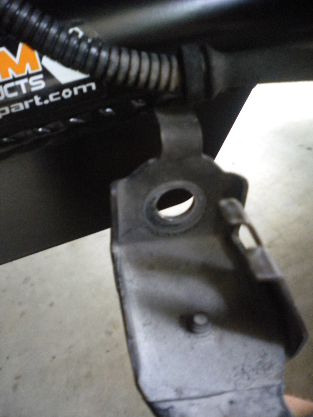
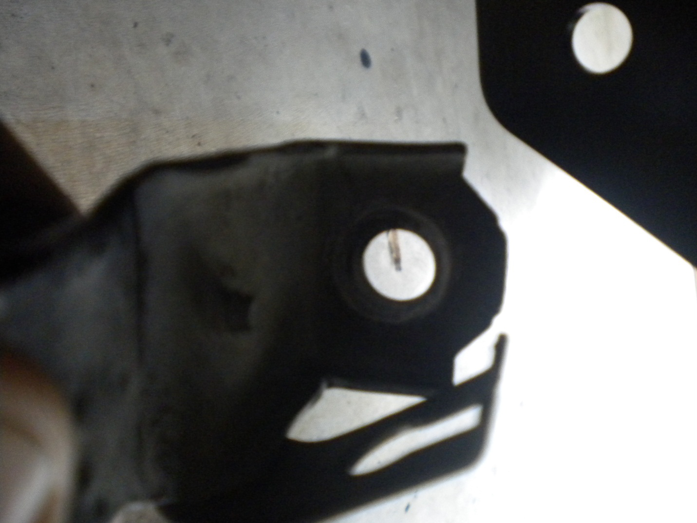
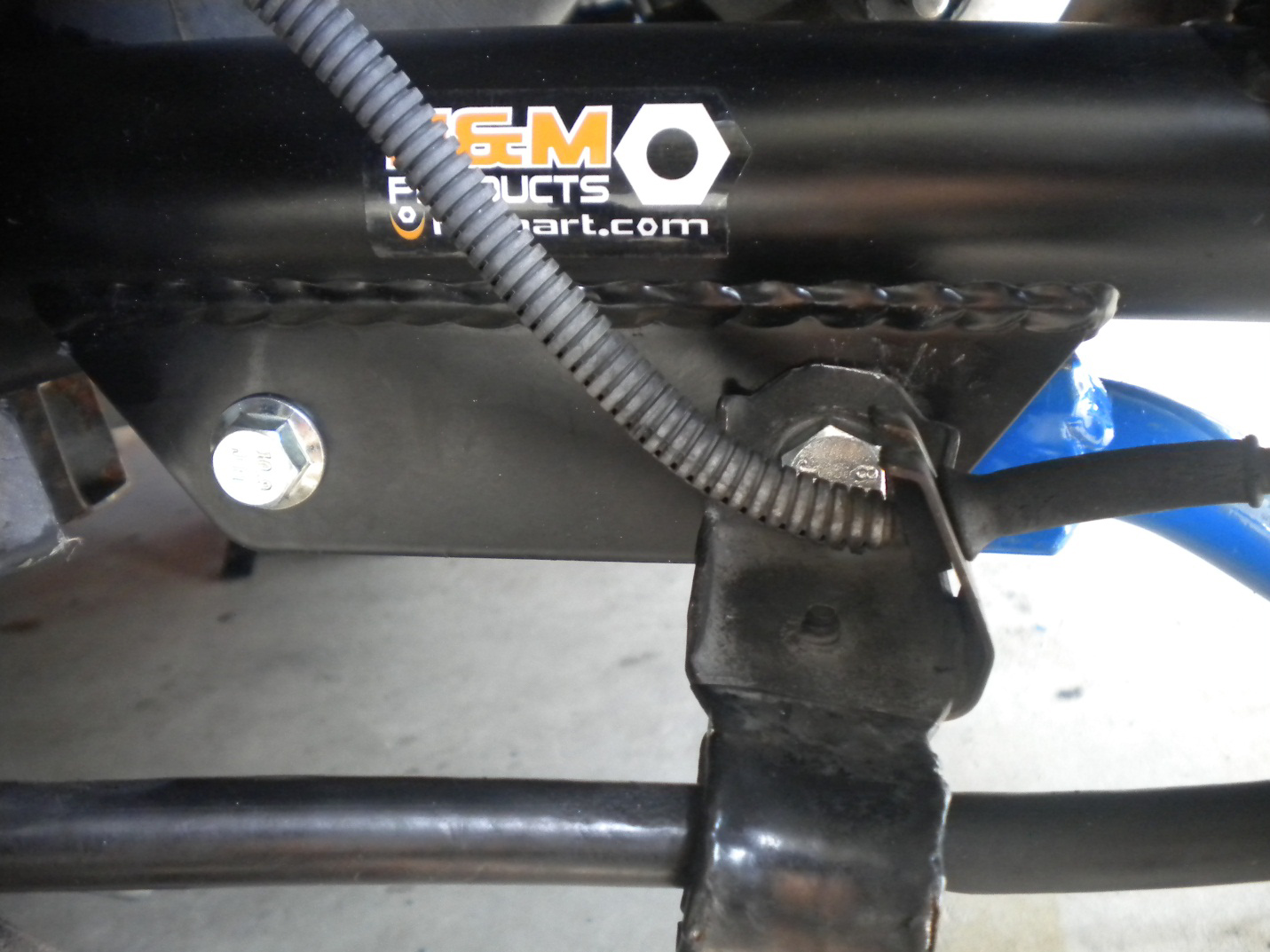
15. With both ends of the control arm secure, it is time for a small modification to the ABS sensor bracket. The top bend will need to be removed as it will not sit flush on the new LCA.
16. Now bolt up the sway bar using the 15mm socket. Torque bolts to 41 ft*lbs.
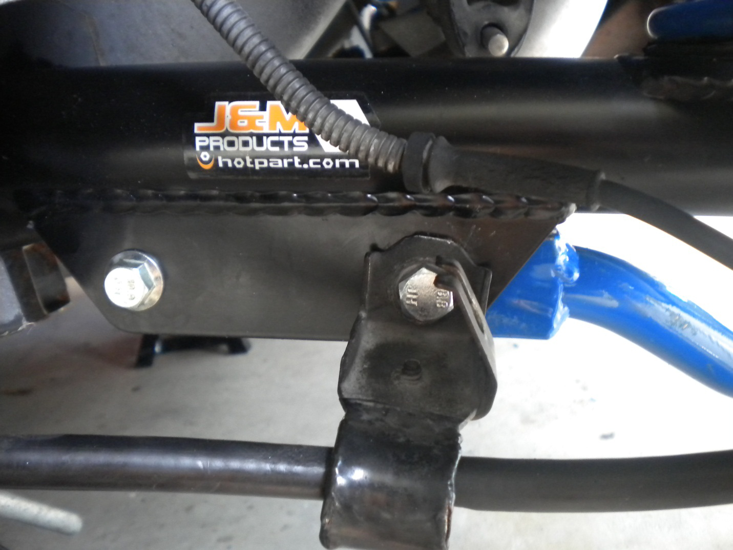
17. Replace the ABS sensor line into its bracket.
18. Mount the wheels, lower the car and torque the lugs. Remove all chalks from around front tires.
19. New J and M LCAs are now installed. Enjoy harder launches and greatly improved handling.
Installation Instructions written by AmericanMuscle customer John Collmann 10/01/2012
