FREE 1 to 3-Day Delivery on Orders $149+ Details
How to Install Maximum Motorsports Bolt-Through Style Bumpsteer Kit (79-93 All) on your Ford Mustang

Shop Parts in this Guide
Read all instructions before beginning work. Following instructions in the proper sequence will ensure the best and easiest installation.
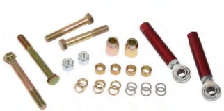
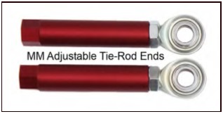
The MM Adjustable Tie-Rod Ends are designed to allow the adjustment of the steering geometry to minimize the amount of bumpsteer. “Bumpsteer” is when the front toe setting changes as the suspension moves up and down. This happens when the arc that the spindle travels during suspension compression and droop is not the same as the arc of the tie-rod end. If the toe changes more than a very small amount, the front wheels begin steering themselves without any input from the driver. This makes the car feel unstable and unpredictable over bumps, with body roll or brake dive. The arc of the spindle and the arc of the tie-rod end are determined by the lengths of the links involved and their physical location with respect to each other. When the front suspension is heavily modified, such as relocated inner control arm pivots, or swapping spindles with different tie-rod end locations, the tie-rod geometry must be restored to minimize bumpsteer.
SPRING REMOVAL INSTRUCTIONS
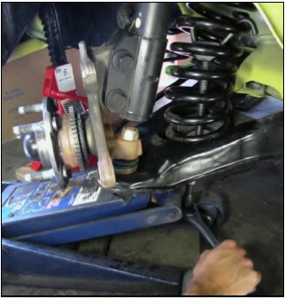
1. Jack up the car and place it safely on four jack stands. The jack stands must be positioned under the chassis, not under the control arms.
2. Remove the front wheels.
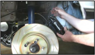
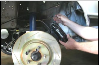
3. Remove the front caliper and hang it securely. Do not let the caliper hang from the brake hose as this can cause unseen damage to the hose. Steel braided hoses are especially susceptible to damage if the caliper is dropped or allowed to hang unsupported.
4. Remove the front brake rotor.
5. Remove the front swaybar end link.
6. Loosen the front strut to spindle bolts, but do not remove them.
7. Spray the tie-rod end taper stud with penetrating oil.
8. Turn the spindle to its maximum toe-in position. Place a floor jack under the control arm near the ball joint. Leave about ½” of clearance between the floor jack and the control arm. This provides the most room for completing Step 13.
9. Loosen the lower ball joint nut until the top of the nut is flush with the top of the ball joint stud.
10. Spray the ball joint taper with penetrating oil.
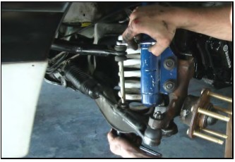
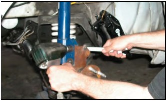
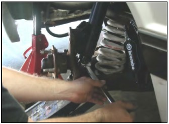
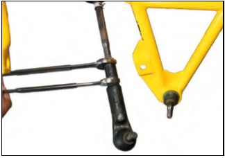
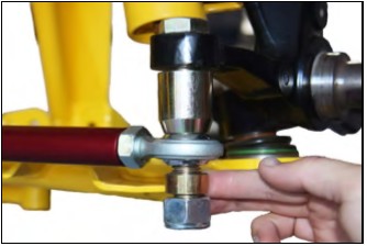
11. Free the tie-rod end by hitting the front of the steering arm with a large hammer.
12. Remove the nut and tie-rod end from the steering arm.
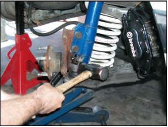
13. Strike the spindle just below the strut, where the ball joint attaches to the spindle, with a large hammer. Do this until the ball joint taper comes free from the spindle. Use a large hammer, and hit it hard.
Stock Springs
If your car is equipped with a coil-over setup, skip to Step 22.
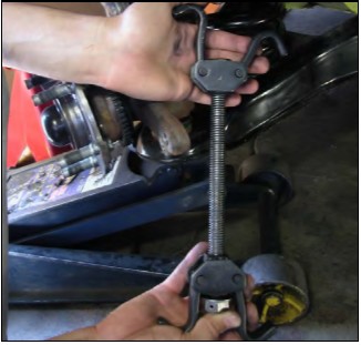
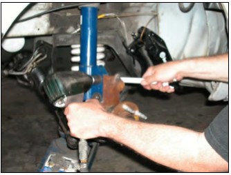
14. The front springs must be compressed so the front suspension can be safely left unattended while you modify your spindles. Use an internally mounted coil spring compressor and compress the front coil spring. Most auto part and equipment rental stores rent this type of spring compressor.
15. Raise the control arm with the floor jack ½”. Remove the ball joint nut completely.
16. Remove the strut to spindle bolts completely.
17. Remove the spindle.
18. Carefully lower the floor jack until the front spring becomes unseated from the upper spring perch and then release the internal spring compressor to free the spring from the control arm.
19. Repeat Steps 3-18 for the opposite side of the car.
20. If you plan to install coil-overs, do so now.
21. Skip to the TIE-ROD INSTALLATION section.
Coil-over Springs
22. Remove the lower strut mounting bolts completely.
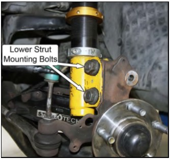
23. Remove the spindle.
24. Repeat Steps 3-23 for the opposite side of the car.
25. Now proceed with the TIE-ROD INSTALLATION section.
TIE-ROD INSTALLATION
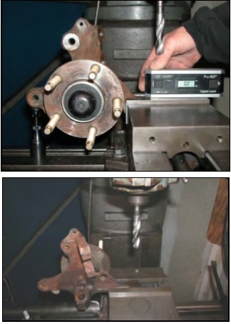
26. Enlarge the tapered holes where the tie-rod ends attached to the steering arm of the spindle to 5/8”. Do this carefully on a milling machine or a very sturdy drill press. DO NOT attempt this with a hand drill or flimsy drill press. Make sure the spindle is secured square to the drill bit with a sturdy vice that is clamped securely to the mill or drill press table. This will help ensure that the hole is drilled round, not eggshaped or oversized. The top side of the hole must be chamfered to allow the bolt head to set down flush to the surface.
27. Loosen the jam nut securing the outer tie-rod end.
28. Hold the MM Adjustable Tie-Rod End next to the stock outer tie-rod end, with the hole of the rod end aligned with the tapered stud of the stock outer tierod end. This will indicate how far the MM Adjustable Tie-Rod End needs to be threaded onto the inner tie-rod. If the MM Adjustable Tie-Rod End is going to be threaded onto the inner tie-rod further than the stock tie-rod end, clean the inner tie-rod end threads to make sure they are free of grime and rust. If the threads are damaged from road debris, make sure to use a thread file or a die to repair the threads, otherwise the tie-rod end sleeve or jam nut threads will be damaged.
29. Again, hold the MM Adjustable Tie-Rod End aligned with the stock outer tie-rod end as in Step 28. Move the jam nut until it is aligned with the end of the MM Adjustable Tie-Rod End. This marks how far to install the MM Adjustable Tie-Rod End for initial assembly.
30. Remove the stock outer tie-rod end.
31. Thread the MM Adjustable Tie-Rod End onto the tierod until it contacts the jam nut. Be careful to avoid moving the position of the jam nut to minimize the toe setting change. Snug the jam nut against the MM Adjustable Tie-Rod End.
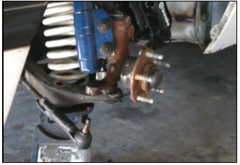
32. Install the modified spindle onto the ball joint. Snug the ball joint nut. If the tapered stud spins in the spindle, it will be necessary snug the nut with an impact gun.
33. Raise the floor jack to align the spindle to the strut. Install the strut bolts from the rearward side with the nuts on the forward side. If you are using springs in the stock location, you must simultaneously align the top of the spring in the upper spring perch of the K-member.
34. If you are using springs in the stock location, you must now release the internal spring compressor.
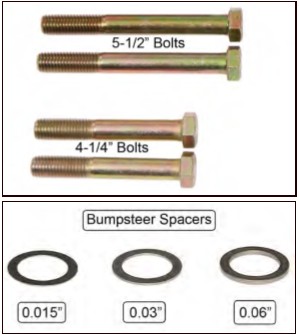
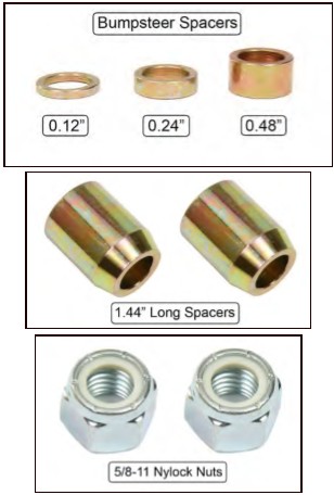
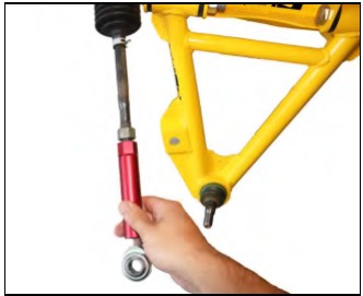
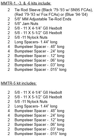
35. From the top, place the 5/8” X 4-1/4” bolt through the drilled 5/8” hole in the steering arm. As a starting point for measuring and adjusting bumpsteer, slide the 1.44” Long Spacers, with the tapered end down, onto the 5/8” bolt. Next slide on the MM Adjustable Tie-Rod End, a 0.48” Long Spacer, and then the 5/8” nylock nut.
36. Torque the 5/8” nut holding the rod end to the spindle to 154 ft-lbs.
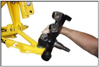
37. Torque the ball joint nut to 129 ft-lbs.
38. Torque the spindle to strut bolts to 148 ft-lbs.
39. Install the brake rotor.
40. Install the brake caliper. Torque the caliper bolts to the factory specs for your caliper.
41. Repeat Steps 26-40 on the opposite side of the car.
BUMPSTEER INSTRUCTIONS
The following is the proper procedure to bumpsteer your vehicle. Please follow the directions carefully to obtain the most accurate bumpsteer readings. All vehicles must have their bumpsteer set.
Preparing For Bumpsteer Measurement
Measuring and adjusting bumpsteer is NOT something most local alignment shops will know how to do. You will either need to find a good racecar prep shop, or learn to do it yourself.
Maximum Motorsports has a bumpsteer gauge tool (MMT-4) that allows the do-it-yourselfer to easily complete the bumpsteer procedure. Please use the following procedure when adjusting the bumpsteer.
Measuring bumpsteer is really rather simple. The suspension is moved through its range of travel, and any changes in the toe setting are measured. There are a number of ways to go about measuring bumpsteer—once you know the basics we are presenting here, you can modify the technique to suit yourself.
1. Center the steering wheel.
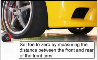
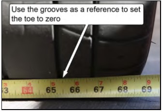
2. With the vehicle resting at ride height, set the toe as close to zero as possible. This can be adequately done using a tape measure. Simply measure the distance between the front and the rear of the front two tires. Use the same grooves in the tread block on each tire as a reference point. Equally adjust the length of the driver and passenger side tie-rods to make the distance between the front and rear faces of both tires equal.
NOTE: After setting the toe to zero, make sure that the tie-rod end jam nuts are tight, as loose nuts will affect the bumpsteer measurements.
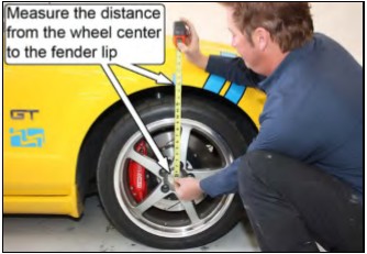
3. With the car on level ground, measure and record the distance from the center of each front wheel to the bottom lip of the fender opening. This distance will be used later to set the “ride height” reference position.
NOTE: We recommend placing a piece of masking tape on the fender lip to mark the measurement location and to record the distance measured.
4. Raise the car and place it safely on four jack stands. The jack stands must be positioned under the chassis rather than the control arms or rear axle.
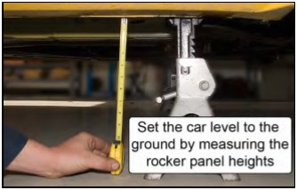
5. Make sure the car is level to the ground by measuring from the bottom of the rocker panels to the ground. Adjust the height of the jack stands to get the car as level as possible. It is critical for accurate bumpsteer measurements that the car does not rock around on the jack stands. If necessary, shim the jack stands so that the weight of the car is evenly supported on all four stands.
6. Remove the front caliper and hang it securely. Do not let the caliper hang from the brake hose as this can cause unseen damage to the hose. Steel braided hoses are especially susceptible to damage if the caliper is dropped or allowed to hang unsupported.
NOTE: Make sure that the calipers are located so that the suspension can be compressed without interference.
7. Remove the front brake rotor.
8. Remove the front swaybar endlink.
9. Remove the front spring.
Stock Location Springs: Refer to Steps 6-18 of the SPRING REMOVAL INSTRUCTIONS. The spindle should be reinstalled when done.
Coil-over Springs: If your car has coil-overs, proceed with the following steps.
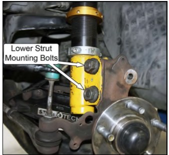
10. Remove the lower strut mounting bolts to the spindle, make sure to hold the control arm from falling and slowly lower it so that it hangs down.
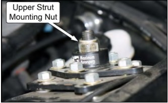
11. Remove the upper strut mounting nut while holding the strut housing with your other hand so the strut assembly does not fall. Remove the strut from the car.
12. Remove the dust boot, spring, and external bumpstop, if present, from the strut.
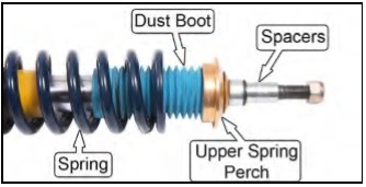
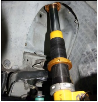
13. Reassemble the spacers and upper spring perch without the spring, dust boot, or external bumpstop, and reinstall the strut back onto the car in the reverse order of removal.
14. Repeat Steps 6-13 for the passenger side of the vehicle once the drivers side has been measured using the following procedure.
Setting up the Bumpsteer Gauge
15. The suspension’s ride height relative to the chassis must be known. This is the dimension measured in Step 3 of this Bumpsteer Instructions.
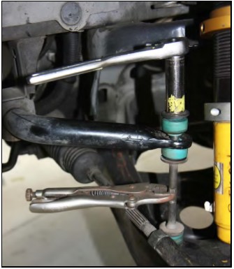
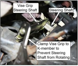
16. It is necessary to lock the wheels perfectly straight with zero play. The steering lock has too much play and does not hold the steering accurately in the straight-ahead position. The best method is to use Vise-Grip pliers on the steering shaft adjacent to the steering rack. Let the handle of the Vice-Grips contact the chassis or k-member. Then, use another Vise-Grip to clamp the first Vice-Grip to the chassis or k-member.
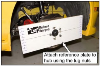
17. Reinstall the brake rotor and attach the flat reference plate to the front hub. Secure the plate to the hub with at least three lug nuts and supplied 1/2” washers. Tighten the lug nuts enough that the plate is firmly fixed to the hub, but not so tight as to distort the plate.
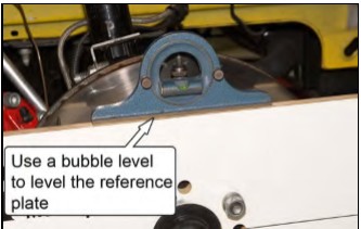
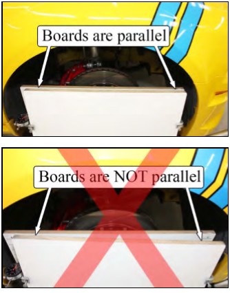
18. Position the reference plate so it is parallel to the ground by using a bubble level or by measuring up from the floor to each end of the plate.
NOTE: The reference plate will not remain parallel as the suspension is cycled. We highly recommend using a bubble level so that the plate can be quickly adjusted parallel to the ground.
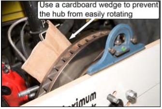
TIP: The hub can be easily kept from rotating by wedging cardboard or something similar between the brake rotor and the spindle.
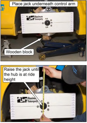
19. Place a jack underneath the front control arm and raise the spindle to normal ride height. Use the dimension D1 you recorded previously to set the distance between the hub center and the bottom of the fender.
NOTE: The jack should be positioned as close to the ball joint as possible. We recommend using a small block of wood between the jack and the control arm.
NOTE: Make sure that the wood block or jack does not contact the rotor as the suspension is cycled. If contact is made, the measurements will not be accurate.
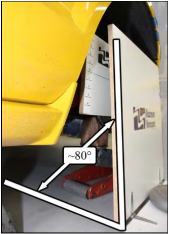
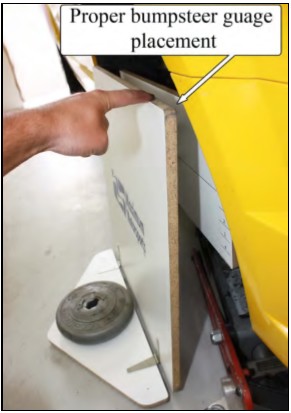
20. Set the bumpsteer gauge into position. The base of the bumpsteer gauge must be away from the car enough that the vertical portion of the bumpsteer gauge wants to fall toward the reference plate. Doing this lets the pointers (not installed yet) follow the reference plate as you cycle the suspension.
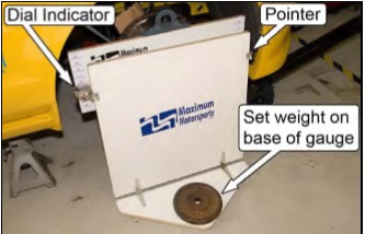
21. Place a heavy weight on the base of the bumpsteer gauge to prevent it from moving. A dumbbell or sandbag works well.
22. The dial indicator and the fixed pointer must be attached to the bumpsteer gauge at this point. When viewing the gauge from the side of the vehicle, attach the dial indicator to the rearward edge of the bumpsteer gauge and attach the fixed pointer to the forward edge of the bumpsteer gauge by hand tightening the clamp bolts. The pointers should be facing the reference plate.
NOTE: Remember when checking the bumpsteer on the opposite side of the vehicle, the positions of the dial indicator and the fixed pointer must be swapped so that the dial indicator is still located on the rearward edge of the bumpsteer gauge.
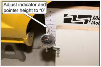
23. Adjust the vertical positions of the dial indicator and the pointer on the gauge so their tips are at the same height as the “0” (normal ride height) marks on the reference plate. After positioning the dial indicator and the pointer it may be necessary to readjust the position of the gauge base to maintain the correct position of the vertical portion of the gauge, so it wants to fall toward the reference plate.
24. When looking down at the top of the bumpsteer gauge and the top of the reference plate, the two edges should be parallel to each other. This will center the dial indicator in its travel range. Pivot the base of the bumpsteer gauge either towards or away from the reference plate to make them parallel within 1/4” of each other.
Measuring Bumpsteer
IMPORTANT NOTE: The process of measuring bumpsteer involves cycling the suspension from full droop to full bump and measuring the toe change at discrete height intervals. On vehicles using rubber control arm pivot bushings, this poses a problem because the rubber is bonded to the bushing surfaces and is not free to rotate. Instead, the bushings deflect, and the amount and direction of deflection varies, depending on how the control arm is loaded and on the condition of the bushings.
Because of this, it is important to never release the jack during a test cycle. Doing so will cause the bushings to become unloaded slightly, causing the reading on the dial indicator to be incorrect. If the suspension is raised above the desired height interval, it is necessary to restart the test from the full droop position.
25. Lower the jack so that the suspension is at full droop. Then, raise the jack about ¼” to slightly compress the suspension, so that there is a small load on the jack.
26. Level the reference plate so that it is parallel to the ground.
NOTE: The reference plate will need to be constantly adjusted and made parallel to the ground as the suspension is cycled through its travel range.
27. Using the jack, raise the control arm so that the dial indicator and the fixed pointer are on the nearest mark on the reference plate. Be sure to check that the reference plate is level as the suspension is being compressed. It may be helpful to have a friend operate the jack while you level the reference plate.
28. Zero the dial indicator by rotating the face until the needle is aligned with the “0” mark.
29. Raise the suspension up 1” inch and observe the dial indicator—it will give a direct measurement of the toe change. Record the dial indicator reading on the chart at the end of these instructions, next to the corresponding hub height.
NOTE: If the rear of the reference plate is moved in towards the center of the car, then the toe setting changed towards toe-out (- value). This would result in the dial indicator rotating in a counter-clockwise rotation. If the rear of the reference plate is moved away from the center of the car, then the toe setting changed towards toe-in( value). This would result in the dial indicator rotating in a clockwise rotation.
30. Raise the control arm to the next inch mark making sure to level the reference plate as necessary. Record the dial indicator reading on the chart at the end of these instructions, next to the corresponding hub height.
31. Repeat Step 30 until the suspension reaches full bump. It most cases, this will be at a point between two reference marks. Measure the distance between the two reference marks and record this on the chart along with the dial indicator reading.
NOTE: Avoid lifting the car, as this will affect the last dial indicator reading. It is not necessary to fully compress the suspension; getting within ½” is close enough.
32. We recommend that you repeat the test, cycling from full droop to full bump, recording all of the dial indicator readings. If all measurements do not repeat closely (within a few thousandths of an inch) then you should examine your testing technique for errors.
33. Once you are sure that the readings are accurate, it is necessary to zero your recorded readings to the normal ride height reference point. This is done by subtracting the dial indicator reading at normal ride height from the readings taken at each reference point. Use the chart at the end of these instructions to record your data.
Adjusting Bumpsteer
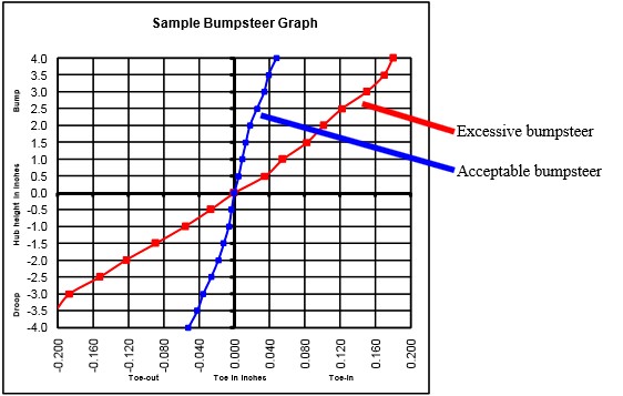
Altering the height of the outer tie-rod end by using the MMTR Adjustable Tie-rod Ends is the easiest method of adjusting bumpsteer on the car. Changing the height of the outer tie-rod end (relative to the steering arm) changes the arc that the tie-rod end makes, relative to the arc that the spindle makes, as the wheel travels up and down. For the stock suspension geometry, as the tie-rod end is raised closer to the spindle steering arm, the vehicle will exhibit increased toe-in under bump. Conversely, as the tie-rod end is lowered relative to the spindle steering arm, the vehicle will exhibit increased toe-out under bump.
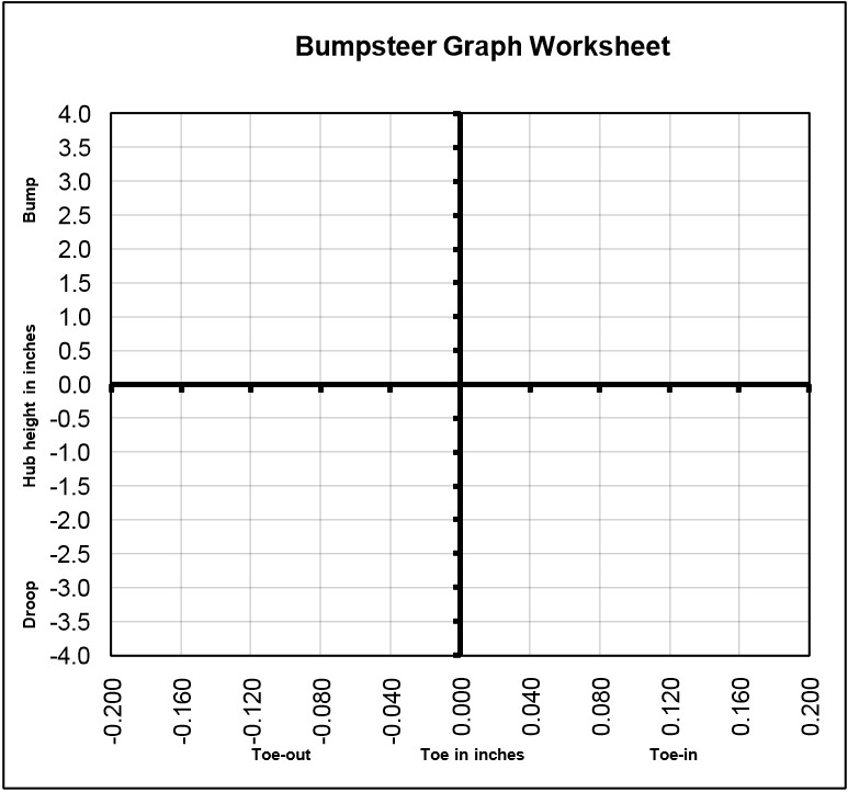
By creating a graph of the toe change vs. suspension movement, the change in toe can easily be seen. The general rule of thumb when adjusting bumpsteer is to keep any toe change to less than 0.020” per inch of suspension travel. A graph of this would show a line that has a steep slope, which is almost vertical. The graph at the end of these instructions is what an acceptable bumpsteer curve looks like.
34. Plot your toe change measurements vs. suspension movement on the provided graph. At the zero reference height (normal ride height) the toe change will always be zero. The shape of the bumpsteer curve will indicate which direction you need to move the outer tie rod end in order to minimize the bumpsteer.
35. If the car has excessive toe-in under bump and excessive toe-out under droop, you need to lower the outer tie-rod end. If the car has excessive toe-out under bump and excessive toe-in under droop, you need to raise the outer tie-rod end.
36. The general rule of thumb is to keep any toe change to less than 0.020” per inch of suspension travel. This may not always be possible at all points in the range of suspension travel. You may have to trade off reduced toe change in one range of suspension travel for more toe change at another point on the bumpsteer curve. Remember that minimizing toe change in the first inch of bump travel is most important. Reducing the amount of toe change in bump is more important than in droop.
37. Adjusting bumpsteer involves a bit of experimentation. Add or subtract spacers from between the tie-rod end and the steering arm of the spindle. Then repeat your bump steer measurements. Compare the new bumpsteer curve to your previous curve. Based on the results of your change, make further adjustments to the spacer stack and repeat the test. Eventually you will be able to reduce your car’s bumpsteer to the minimum amount possible.
NOTE: In some cases, the longer 5/8” bolt may need to be used. If the shorter 5/8” bolt does not protrude from the Nylock Nut when torqued, then use the longer 5/8” bolt.
38. Repeat Steps 15-37 to measure bumpsteer on the driver side. If the arrangement of spacers is more than 1/4” different from the passenger side, you should inspect all front suspension components for damage or check for a faulty alignment.
39. Once the bumpsteer is finalized, torque the 5/8” nylock nuts holding the bumpsteer arrangements to 154 ft-lb.
40. Re-install the front springs, calipers, and swaybar end-links; torque all components to the manufacturer’s specifications.
41. Reset the toe. Changes in the bumpsteer spacer arrangement will change the toe setting, but later changes in the toe setting when the car is aligned will not significantly affect bumpsteer.
42. Remember—any time you make a change in caster the bumpsteer will be affected. Small changes to the static camber setting will have a negligible effect on bumpsteer, although it will alter the toe setting.
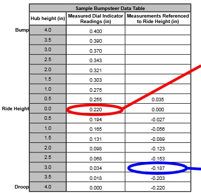
1. Record all the dial indicator readings into the second column of the worksheet. Toeout values are (-) negative and toe-in values are ( ) positive.
2. Take note of the “Measured Dial Indicator Reading” at the 0.0 “Hub Height”. In this example it is 0.220” inches.
3. Subtract the value (0.220 in this example) from each of the “Measured Dial Indicator Readings” and record the resulting number in the “Measurements Referenced to Ride Height” column.
Example at 3” of droop travel:
0.034 - 0.220 = -0.187
4. Graph each point in the “Measurements Referenced to Ride Height” column. Once done, draw a line connecting all of the points. An acceptably small amount of bumpsteer will produce a steep line, as shown in the example to the left.
NOTE: Make copies of this sheet for use on the driver side of the vehicle, as well as for future use.
NOTE: Dial indicator readings that are toe-in, should be recorded as ( ) values. Dial indicator readings that are toe-out, should be recorded as (-) values.

NOTES: Make copies of this sheet for use on both sides of the vehicle, or log on to www.maximummotorsports.com to download a copy of these instructions.