FREE 1 to 3-Day Delivery on Orders $149+ Details
How to install an MSD Power Grid 7 System on your 1979-1995 Mustang
Shop Parts in this Guide
Installation
Parts Included:
- 1 - MSD PowerGrid 7 Ignition Controller
- 1 - Wire Harness
- 1 - Parts Bag
WARNING: During installation, disconnect the battery cables. When disconnecting, always remove the Negative cable first and install it last.
Note: Solid core spark plug wires cannot be used with an MSD Ignition Control.
The Power Grid 7 Ignition Control was specifically designed to pair with the Power Grid System Controller, PN 7730. This Ignition system is designed for racing applications; it is not for sale for legal use on highways.
SPECIFICATIONS
Spark Energy: 200 – 220 milliJoules/spark
Primary Voltage: 545 – 570 volts
Secondary Voltage: 50,000 volts plus
Spark Series Duration: 20° Crankshaft Rotation
RPM Range: 15,000 rpm with 14.4 volts
Voltage Required: 12 – 18 volts, Negative Ground
Current Draw: 1.3 Amp per 1,000 rpm
Weight and Size: 2.9 LBS, 7.5”L x 5”W x 2.25” H
GENERAL INFORMATION
BATTERY
An MSD Power Grid 7 Ignition Control will operate on any negative ground, 12 volt electrical system with a distributor. The MSD can be used with 18 volt batteries and can withstand a momentary 24 volts in case of jump starts. The Ignitions will deliver full voltage with a supply of 10 - 18 volts and will operate with a supply voltage as low as five volts.
If your application does not use an alternator, allow at least 15 amp/hour for every half hour of operation. If the engine is cranked with the same battery or other accessories such as an electric fuel or water pump, the amp/hour rating should be higher.
COILS
It is recommended to use either the Pro Power HVC, PN 8251, or Pro Power HVC II, PN 8261. If you have any questions concerning coils, contact our Customer Service Department at (915) 855-7123.
SPARK PLUGS AND WIRES
Spark plug wires are very important to the operation of your ignition system. A good quality, helically wound wire and proper routing are required to get the best performance from your ignition, such as the MSD 8.5mm Super Conductor.
Note: Solid Core spark plug wires cannot be used with an MSD Ignition.
A helically, or spiral wound wire must be used. This style wire provides a good path for the spark to follow while keeping Electro Magnetic Interference (EMI) to a minimum. Excessive EMI, such as the amount that solid core wires produce, will interfere with the operation of the MSD and other electronics on your car.
Spark Plug Wire Routing: Correct routing of the plug wires is also important to performance. Wires should be routed away from sharp edges and engine heat sources. If there are two wires that are next to each other in the engine’s firing order, the wires should be routed away from each other to avoid inducing a spark into the other wire. For example, in a Chevy V8, the firing order is 1-8-4-3-6-5-7-2.
The #5 and #7 cylinders are next to each other in the engine and in the firing order. If the voltage from the #5 wire is induced into #7 detonation could occur and cause engine damage.
To add more heat protection to your plug wires, MSD offers Pro-Heat Guard, PN 3411. This is a glass woven and silicone coated protective sleeve that you slide over your plug wires. For extra protection of the spark plug boots, MSD offers Pro-Heat Boot Guard, PN 3412.
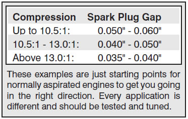
Spark Plugs: Choosing the correct spark plug design and heat range is important when trying to get the best performance possible. Since there are so many engine combinations and manufacturers, MSD does not recommend which plug or gap is exactly right for your application. It is recommended to follow the engine builder or manufacturer’s specification for spark plugs. With that, you can then experiment with the plug gap to obtain the best performance. The gap of the plugs can be opened in 0.005” increments, then tested until the best performance is obtained. MSD judges the plug gap by compression and components:
Note: A larger plug gap taxes the cap, rotor and spark plug wires. Always inspect the cap and rotor to make sure they are in good condition.
MISCELLANEOUS INFORMATION
Sealing: Do not attempt to seal the MSD. All of the circuits of an MSD receive a thick conformal coating of Humi-Seal. This sealant protects the electronics from moisture. If you were to seal the unit, any moisture or water that may seep in through the wiring grommets will not be able to drain and may result in corrosion.
Welding: If you are welding on your vehicle, to avoid the chance of damage, always disconnect both heavy power cables of the MSD. (You should also disconnect the tach ground wire too).
Distributor Cap and Rotor: It is recommended to install a new distributor cap and rotor when installing the MSD Ignition Control. The cap should be clean inside and out especially the terminals and rotor tip. On vehicles with smaller caps, it is possible for the air inside the cap to become electrically charged causing crossfire which can result in misfire. This can be prevented by drilling a couple vent holes in the cap. The holes should be placed between the terminals, at rotor height and face away from the intake. If your environment demands it, place a small piece of non-metallic screen over the hole to act as a filter.
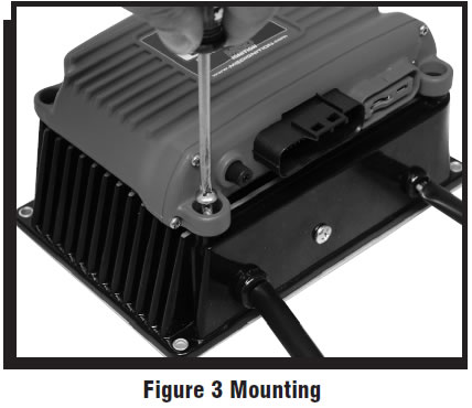
MOUNTING
The Power Grid 7 can be mounted in most any spot that would be acceptable for other MSD boxes. However, if the Ignition is to be mounted with the System Controller paired in the top mounting position particular attention should be paid to the heat around the units. In this stacked position it is recommended that the units be mounted inside the vehicle cabin. When you find a suitable location to mount the unit, make sure the wires of the ignition reach their connections. Hold the ignition in place and mark the location of the mounting holes. Use a ¼” drill bit to drill the holes. Install the vibration mounts to the ignition and mount the unit. The Power Grid System Controller (PN 7730) is designed to be mounted on top of the PN 7720 Ignition. Be sure to mount the Power Grid System Controller so the USB connector and Micro-SD card are accessible. The PN 7730 comes with thread-turning (aka. Self-tapping) screws that will cut into the walls of the pre-drilled holes on the top corners of the Power Grid-7.
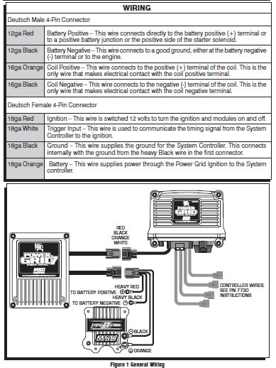
WIRING
GENERAL WIRING INFORMATION
Wire Length: All of the wires of the MSD Ignition may be shortened as long as quality connectors are used or soldered in place. To lengthen the wires, use one size bigger gauge wire (10 gauge for the power leads and 16 gauge for the other wires) with the proper connections. All connections must be soldered and sealed.
Grounds: A poor ground connection can cause many frustrating problems. When a wire is specified to go to ground, it should be connected to the battery negative terminal, engine block or chassis. There should always be a ground strap between the engine and the chassis. Always securely connect the ground wire to a clean, paint free metal surface.
Noise Capacitor: MSD offers a Noise Capacitor or Filter to help eliminate EMI noise. This capacitor, PN 8830, will also protect the MSD and accessories from voltage and current spikes.
ROUTING WIRES
The MSD wires should be routed away from direct heat sources such as exhaust manifolds and headers and any sharp edges. The trigger wires should be routed separate from the other wires and spark plug wires. It is best if they are routed along a ground plane such as the block or firewall which creates an electrical shield.
WARNING: The MSD Power Grid Ignition is a capacitive discharge ignition. High voltage is present at the coil primary terminals. Do not touch the coil or connect test equipment to the terminals.
PRESTART CHECKLIST
- The Power Grid 7, PN 7720, MUST be properly connected to the System Controller, PN 7730.
Consult the PN 7730 Quick Start Guide to ensure starting parameters.
- The only wires connected to the coil terminals are the MSD Orange to coil positive ( ) and MSD Black to coil negative (-).
- The MSD power leads are connected directly to the battery positive and negative terminals.
- The battery is connected and fully charged if not using a charging system.
- The engine is equipped with at least one ground strap to the chassis. Ground straps connecting both heads to the block and then to the chassis are ideal.
TROUBLESHOOTING
Every MSD Ignition undergoes numerous quality control checks including a burn-in test. If you experience a problem with your MSD, our research has shown that the majority of problems are due to improper installation or poor connections. The Troubleshooting section has several checks and tests you can perform to ensure proper installation and operation of the MSD. If you have any questions concerning your MSD, call our Customer Support Department at (915) 855-7123, 7 - 5 MST.
MISSES AND INTERMITTENT PROBLEMS
Experience at the races has shown that if your engine is experiencing a miss or hesitation at higher rpm, it is usually not directly ignition related. Most probable causes include a coil or plug wire failure, arcing from the cap or boot plug to ground or spark ionization inside the cap. Several items to inspect are:
- Always inspect the plug wires at the cap and at the plug for a tight connection and visually inspect for cuts, abrasions or burns.
- Inspect the Primary Coil Wire connections. Because the MSD is a Capacitive Discharge ignition and it receives a direct 12 volt source from the battery, there will not be any voltage at the Coil Positive ( ) terminal even with the key turned On. During cranking or while the engine is running, very high voltage will be present and no test equipment should be connected.
- Make sure that the battery is fully charged and the connections are clean and tight. If you are not running an alternator this is an imperative check. If the battery voltage falls below 10 volts during a race, the MSD output voltage will drop.
- Is the engine running lean or excessively rich? Inspect the spark plugs and fuel system.
- Inspect all wiring connections for corrosion or damage. Remember to always use proper connections followed by soldering and seal the connections completely.
If everything checks positive, use the following procedure to test for spark. MSD also offers an Ignition Tester, PN 8998. This tool allows you to check your complete ignition system while it is in the car as well as the operation of rpm limits, activated switches and shift lights.
CHECKING FOR SPARK
To test the Power Grid 7 separate from the System Controller perform the following steps:
1. Test with the full system together following instructions supplied with the System Controller, PN 7730 using the following steps. If there is spark the system is working properly, there is no need to test further. If there is no spark, continue testing using the next sets of steps.
If triggering the ignition with the White wire:
1. Make sure the ignition switch is in the “Off” position.
2. Remove the coil wire from the distributor cap and set the terminal approximately 1/2” from ground.
3. Disconnect the MSD White wire from the distributor’s points or ignition amplifier.
4. Turn the ignition to the “On” position. Do not crank the engine.
5. Rapidly tap the White wire to ground many times. When the wire is pulled from ground, a spark should jump from the coil wire to ground. NOTE: The system must see a minimum of 90 rpm in order to fire, so the multiple taps must be in rapid succession. If spark is present, the ignition is working properly. If there is no spark skip to steps on page 6:
If triggering with the Magnetic Pickup:
1. Make sure the ignition switch is in the “Off” position.
2. Remove the coil wire from the distributor cap and set the terminal approximately 1/2” from ground.
3. Disconnect the MSD magnetic pickup wires from the distributor.
4. Turn the ignition to the “On” position. Do not crank the engine.
5. With a small jumper wire, short the MSD’s Green and Violet magnetic pickup wires together. Each time you break this ground (rapidly), a spark should jump from the coil wire to ground. NOTE: The system must see a minimum of 90 rpm in order to fire, so the multiple taps must be in rapid succession. If spark is present, the ignition is working properly. If there is no spark skip to steps on page 6:
If there is no spark:
1. Inspect all of the wiring.
2. Substitute another coil in the system and repeat the original test. If there is now spark the coil is at fault.
3. If there is no spark, check to make sure there is 12 volts on the small Red wire from the Power Grid 7 during both cranking and run. If these steps do not correct a problem, continue with the trouble shooting steps below.
Isolating and checking the Power Grid 7 Ignition.
1. Make sure power to the ignition is OFF.
2. Disconnect the Power Grid 7 Ignition from the System Controller (only the Deutsch connector between the two).
3. Isolate the White wire in that set and attach a jumper wire.
4. Turn on power to the ignition system.
5. Jump the White wire to a 12 volt power source. If the system creates multi-spark when the wire receives power it is working properly. You do not need to tap the wire to power multiple times, only touch and hold to power once.
After you are sure that the box has received a power signal and you have checked for spark, remove power from the White wire.
If there was no spark with the full system connected, but there is spark when the Power Grid 7, PN 7720, is tested by itself, there is likely an issue with either the wiring connections or the System Controller, PN 7730.