FREE 1 to 3-Day Delivery on Orders $149+ Details
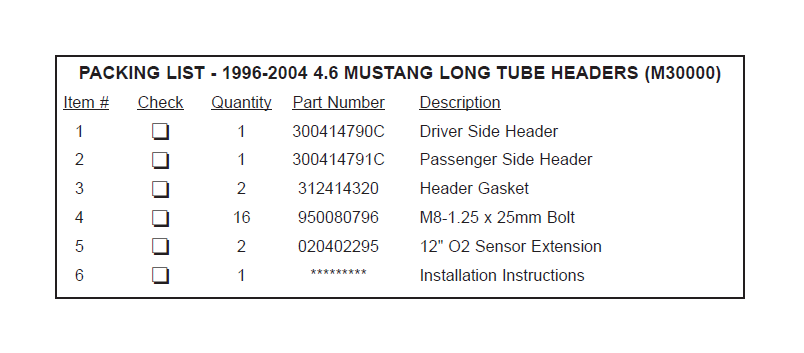
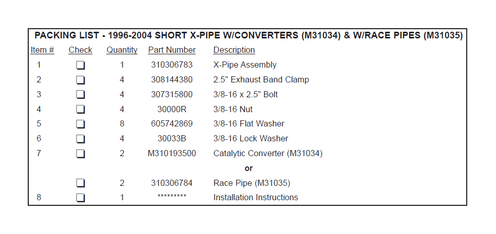
How to install a SLP Catted Shorty X-Pipe on your 1996-2004 Mustang

Shop Parts in this Guide
Installation
WARNING: SLP recommends allowing the vehicle to cool (not running) for five hours before beginning the installation. SLP recommends wearing safety glasses for the complete installation.
WARNING: Too avoid the chance of electrical shock or damage to your vehicle's electrical system, disconnect both the negative and positive battery leads (in that order) at the battery.
NOTE: These headers and x-pipe were designed to work as a system and will install without any cutting or fabrication. Use of these headers or x-pipe with another manufacturer's headers or x-pipe/h-pipe may require cutting and fabrication and SLP cannot guarantee compatibility.
NOTE FOR CONVERTIBLES: These headers were designed to fit coupe models. On convertible models modification to the engine K-member reinforcement brace may be required to gain proper clearance for the header collectors. If such modification is required you must be sure that adequate chassis reinforcement is maintained after the K-member reinforcement brace has been modified.
INSTALLATION INSTRUCTIONS
1. Raise the vehicle to allow for a sufficient work area underneath the vehicle. A vehicle lift will make this installation much easier, however, raising the vehicle can be accomplished using ramps or a jack with jack stands.
REMOVAL OF THE OLD EXHAUST PARTS:
2. Disconnect the tailpipe and muffler assembly by unbolting the 2 flanges from the H-pipe and removing the exhaust hangers from the rubber insulators. If you are retaining your old tailpipes and mufflers you can just move them out of the way to allow enough clearance for removal of the old h-pipe and installation of the new x-pipe.
NOTE: If you are removing the original tailpipes and mufflers you may need to cut the old pipes in the vicinity of the rear axle or disconnect the shocks to gain enough suspension clearance to remove them.
3. Disconnect the wires from all the oxygen sensors.
4. Remove the nuts from the exhaust manifold to h-pipe studs and remove the original h-pipe assembly*.
*96-98 VEHICLES: You will need to unbolt the additional hanger from the transmission cross member prior to removing the h-pipe. You can discard this hanger, as you will not be reusing it.
5. You may want to remove the oxygen sensors from your old h-pipe and install them in your new system now while access to them is easier. Be sure to reinstall the sensors in the same locations as in the original h-pipe. The front oxygen sensors will be installed in the header collectors.
Note: On 1999 vehicles there is an additional bracket on the transmission mount that the oxygen sensor wire harness attaches to. This bracket may interfere with the oxygen sensors on the SLP x-pipe. You may either trim this bracket to obtain the necessary clearance or simply remove it. Removal can be accomplished fairly easily by first supporting the transmission with a jack. Then simply remove the four bolts retaining the transmission cross member and mount to the floor followed by the 2 bolts retaining it to the transmission itself. Lower the cross member and mount, remove the bracket, and reinstall the cross member and mount in the reverse procedure. Whether you decide to trim the bracket or remove it you must make sure the wire harness is clear of any exhaust parts when the installation is complete. Using tie wraps to secure the harness to the cross member is a good idea.
6. Disconnect the EGR tube from the driver side exhaust manifold and from the EGR valve on top of the engine. This should allow you to move the tube up out of the way. You may also need to disconnect the two rubber hoses found on the tube, but label where they came from as it is important they be reinstalled in the exact same locations.
7. Disconnect the electrical connections at the starter solenoid and remove the three bolts retaining the starter motor to the transmission bell housing. Remove the starter motor/solenoid.
8. Remove the bolt retaining the driver side of the front sub frame brace and loosen the bolt on the passenger side. Rotate it towards the front of the vehicle to gain additional clearance.
9. Completely remove the steering column intermediate shaft pinch bolt from the coupler on the steering rack. Slide the intermediate shaft coupling off of the steering rack and let it hang straight down out of the way.
10. Remove the 8 nuts on the driver side exhaust manifold and remove the manifold. Do not be concerned if some of the studs come out with the nuts, as you will need to remove all 8 manifold studs from the cylinder head anyway. Repeat this entire procedure on the passenger side.
11. Remove the bolt retaining the dipstick tube and remove the dipstick tube.
12. Remove the gaskets and any remaining manifold studs. The studs have a 5mm hex head on the end.
HEADER INSTALLATION:
NOTE: Before beginning header installation take some of the header bolts, coated with a suitable lubricant, and thread one into each of the holes to assure proper thread engagement. Some may be too tight to thread in by hand. This is normal, but light effort with a wrench should allow them to thread in easily.
13. Remove the nuts from both engine mount studs so that the engine may be raised for greater access. There is no need to raise the engine at this point.
14. If it has been removed place the EGR tube in it's correct location but do not connect it to anything at this time.
15. Hold a gasket in place on the driver side cylinder head and thread the two upper rear most bolts into place through the gasket. This will hold the gasket in place during the remainder of the installation. Leave enough room under the bolt heads so that the two corresponding notched holes on the header flange will slide under without damaging the gasket. Insert a bolt in the second hole from the rear on the bottom and tape in place as shown in Photo 1. Otherwise, putting this bolt in after the header is in place will be difficult.
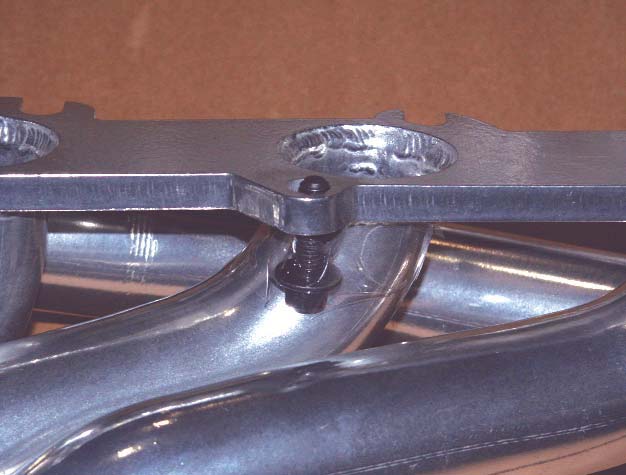
PHOTO 1
16. Raise the front of the driver side header into place. Insert the upper forward most bolt through the flange and the gasket and thread it into the cylinder head. Do not raise the rear of the header into position at this time.
NOTE: As you raise the header into position raise the intermediate steering shaft along with it, because you will be unable to raise it into position once the header is in place.
You do not need to connect it to the steering rack yet, just place it in a position that will allow you to do so once the header is in place.
17. While the rear of the header is still hanging, connect the EGR tube to the EGR fitting on the header and tighten it, but leave it just loose enough for adjustment.
18. Raise the rear of the header and slide it into place under the two rearmost upper bolts being careful not to damage the gasket. Then thread the most rearward lower bolt into the cylinder head and hand tighten.
19. Install the remainder of the header bolts hand tight.
20. Torque all the header bolts to 15 ft/lbs starting at the upper rearmost bolt and working forwards while alternating between the upper and lower bolts. Some of the bolts will need to be accessed from above. To do so you will need to raise the engine on the driver side. Do not raise the entire engine, just rotate it towards the passenger side. Be careful not to raise the engine far enough to damage any components. Only a few extra inches of clearance are necessary to access all the upper bolts. To access the lower bolt third from the rear of the engine you may find it easiest to remove the engine mount entirely. Just remove the three bolts and move it out of the way.
NOTE: Raising the engine can be accomplished by placing a suitable jack on the oil pan rail (with a block of wood to prevent damage to the pan rail) on the front corner of the block and jacking. You can also use an engine hoist if you have access to one. You may need to lower the vehicle off the jack stands or ramps to jack the engine up if your jack does not extend high enough. After supporting the engine securely with blocks of wood you can lift the vehicle back onto the jack stands.
CAUTION: For safety the engine must always be properly supported with blocks of strong wood (such as pieces of a 2x4) or other suitably strong material between the engine cradle and the side of the engine block before continuing the installation. Choose the location so that the blocks of wood do not impede access to any of the header bolts, but also be careful not to support the engine by anything that can be damaged, such as the oil pan. Two small pieces of a 2x4 between the engine mount and the frame should suffice. If you have removed the engine mount, you may need an additional 2x4.
21. If you have removed the engine mount reinstall it at this time and torque the three bolts to 52 lb/ft. Then lower the engine carefully back onto the frame.
22. Repeat steps 15 through 21, minus the EGR tube, for the passenger side header.
23. Reinstall the nuts onto the engine mount studs on both sides and torque them to 111 lb/ft.
24. Reinstall the dipstick and torque the retaining bolt to 89 in/lb. Make sure the oil seal is present and in good condition to avoid potential oil leaks. You will probably need to bend the tube slightly to clear the header flange.
25. Tighten the EGR tube fittings at the EGR valve and at the header. Then reconnect the rubber hoses to the proper nipples on the EGR tube if you have removed them.
26. Reinstall the steering column intermediate shaft onto the steering rack and torque the coupler pinch bolt to 25 ft/lbs.
27. Reinstall the front sub frame brace and torque the bolts to 30 ft/lbs.
28. Reinstall the starter motor and torque the retaining bolts to 18 ft/lb. Reconnect the electrical connections to the starter solenoid.
X-PIPE INSTALLATION:
29. Slide a band clamp over the inlet (notched) end of one of the catalytic converters, and then slide the inlet over the end of the collector on one of the headers. The side of the converter with the heat shield should face upward towards the floor pan of the vehicle. Loosely tighten the clamp. Repeat this procedure on the other header.
For the Race X-Pipe (M31035) just insert the supplied Race Pipes in place of the catalytic converters.
30. Slide a band clamp onto each side of the inlet (notched) end of the x-pipe assembly and slide the whole assembly onto the converter outlets. Loosely tighten the clamps.
31. Reconnect the tailpipes to the new x-pipe using the provided 3/8-16 x 2.5" bolts, nuts, flat washers, & lock washers. Place a flat washer under the head of each bolt and slide it into the flanges with the threaded end towards the rear of the vehicle. Then put a flat washer, lock washer, & nut (in that order) onto each bolt and loosely tighten the bolts.
32. Now adjust all the pipes until the tailpipe tips are located as desired and all the pipes have enough clearance from all suspension, brake lines, fuel tank, driveline, and body parts. The pipes should be parallel with the rocker panels (not the floor pan or sub frames) when viewed from the side. The multi-piece modular design allows the center of the exhaust to sag when all the joints are loose and when tightened in this relaxed position can decrease ground clearance. You may need to support the center of the pipes while tightening them to assure the pipes remain parallel to the rocker panels.
33. Tighten all the clamps and fasteners working from the headers back, while checking and maintaining correct tip location along the way. The x-pipe to muffler flange bolts/nuts should be tightened to 26 lb/ft.
OXYGEN SENSORS:
34. If you have not already done so reinstall the oxygen sensors and reconnect the electrical connectors for each of them. Use the provided oxygen sensor harness extensions to connect the front oxygen sensors. You may need to trim the locating tabs off the connectors on the oxygen sensor for them to plug into the extensions properly. This is because not all of the connectors have the tabs located in the same position. Make sure all wires are routed clear of any exhaust or moving parts to avoid damage to the wires. It may be necessary to use tie wraps to hold the wire harness away.
On 2004 GTs you will probably need a pair of oxygen sensor wire extension harnesses (Part # M31037) to connect the rear oxygen sensors. Route the extension harness over the transmission crossmember to keep them away from the exhaust pipes. NOTE: You will likely need to install oxygen sensor simulators (PN M31038) on the two rear oxygen sensors if you are using the race pipe to avoid setting a diagnostic trouble code (DTC) and illuminating the vehicle's malfunction indicator lamp (MIL).
35. Start the vehicle and inspect for leaks.
36. Double-check all fasteners and clearances after test driving. Adjust as necessary.