FREE 1 to 3-Day Delivery on Orders $149+ Details
How to Install Roush Front Fascia Kit - Unpainted on your Mustang
Tools Required
- Phillips Screw Driver
- Flat Head Screw Driver
- Push-pin Removal tool – Forked prybar
- Ratchet and Extension – 1/4" drive
- 5.5 mm Socket – 1/4" drive
- 7 mm Socket – 1/4" drive
- 8 mm Socket – 1/4" drive
- 10 mm Socket – 1/4" drive
- Pliers
- Wire Stripping Tool
- 1/4" Drill Bit
- Wiring De-pinning tool (Pick Tool)
- Hole Saw (OEM Options Dependent – Parking Sensors)
- Soldering equipment (optional)

Shop Parts in this Guide
STOCK FASCIA REMOVAL
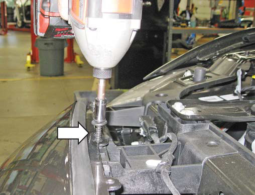
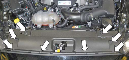
1. Open the vehicle hood and remove eight (8) pushpin retainers and the black plastic closeout panel covering the radiator as shown. Set all parts aside for reinstallation.
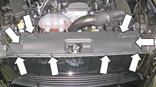
NOTE: The push pins are a two (2) part push pin. Remove the center button fi rst to release the barbs and then remove the push-pin body.

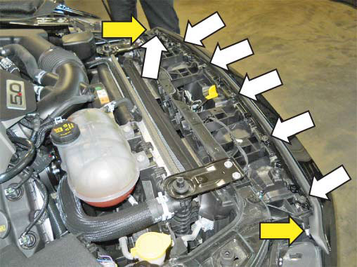
2. Remove the fasteners on the top of the front fascia. There are six (6) 8 mm screws running across the front, as well as two (2) 4.5 mm screws, one at each side of the fascia near the headlamp. SAVE THESE FASTENERS!
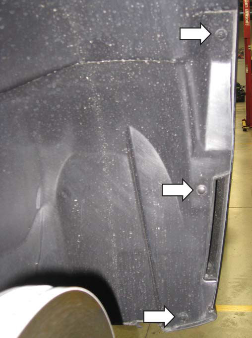
3. Remove the front wheel fender liners by removing the three (3) push pins that hold the liner in place. They run along the edge where the fender liner meets the fender panel. SAVE FASTENERS FOR REINSTALLATION!
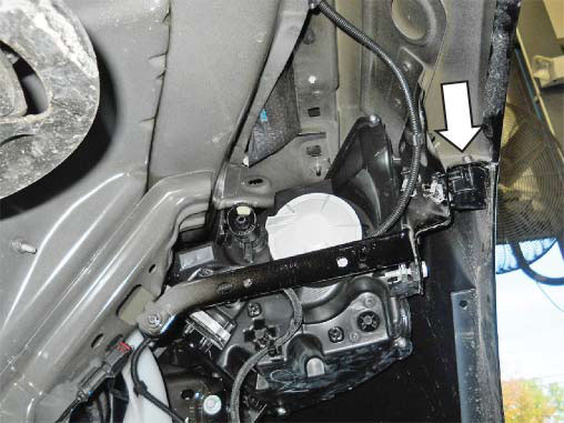
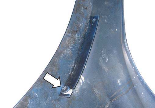
4. Once the fender liners have been removed, you will have access to the two (2) 7 mm fasteners, one on each side of the vehicle, that hold the fascia in place where it meets the fender. Remove these fasteners. They are highlighted below. SAVE FASTENERS FOR REINSTALLATION!
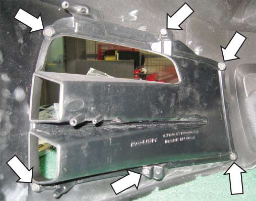
5. For V8 (GT Performance Package) equipped vehicles only, remove the bottom aero panel by removing the ten (10) M4.2 screws. Their locations are shown below.
6. For non-performance package equipped vehicles (V8/V6/I4), remove the twelve (12) M4.2 screws along the front edge, as well as the four (4) M4.2 screws near the center recesses of panel.

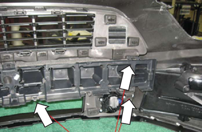
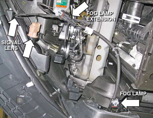
7. With the underbody aero panel removed, disconnect the electrical connectors for the fog lights as well as the turn signals.
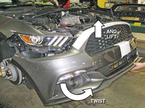
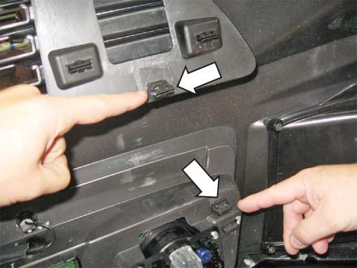
8. Remove the fascia by fi rmly pulling the corner away from the vehicle, then disengage the clips holding it in place.
9. Pull the fascia forward and lift it off the plastic dowel pins located along the top (where the screws were removed in step 2).
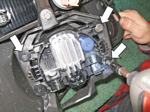
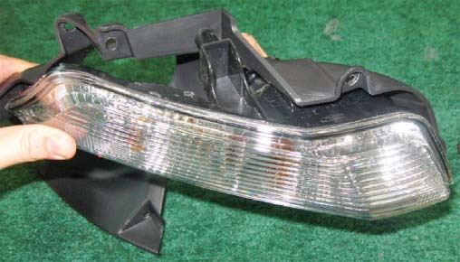
This completes the OEM fascia removal process. OEM FASCIA DISASSEMBLY 1. Remove the three (3) 7 mm screws holding the fog light into the assembly and remove the fog light. SAVE HARDWARE FOR REINSTALLATION!
2. Remove the six (6) 7 mm screws that fasten the pocket trim panel to the fascia. Remove the trim panel from the fascia. SAVE HARDWARE FOR REINSTALLATION!
3. Remove the turn signal lens from the trim piece by removing the three (3) 7 mm screws that fasten them together. SAVE HARDWARE FOR REINSTALLATION!
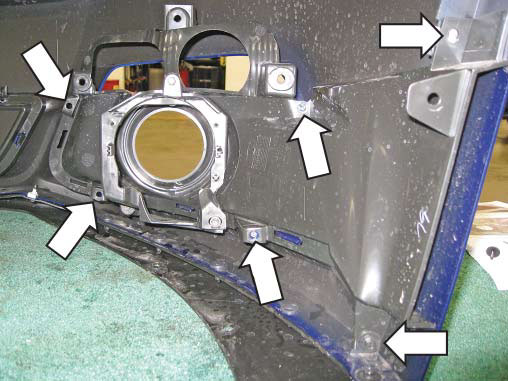
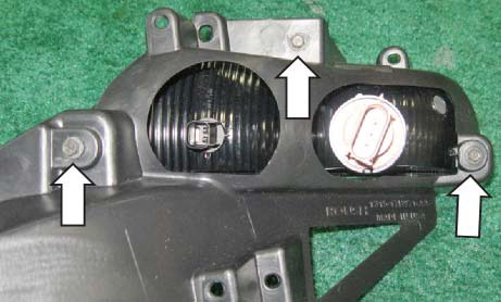
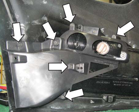
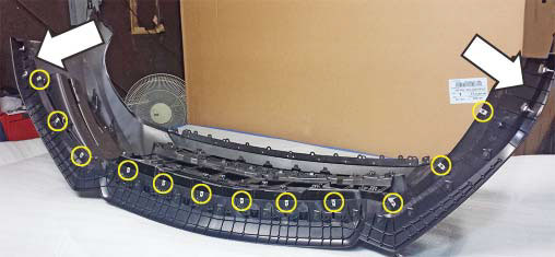
4. Remove the eight (8) 7 mm screws that fasten to the fascia. KEEP ALL HARDWARE FOR REINSTALLATION (including J-clips)
5. Remove the eight (8) push pins retaining the splitter to the fascia, as well as the two (2) corner screws. SAVE ALL HARDWARE FOR REINSTALLATION!
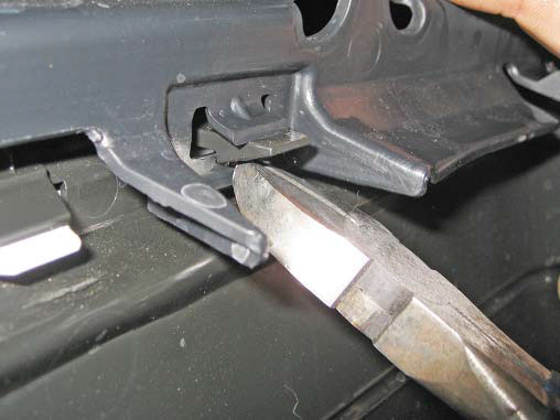
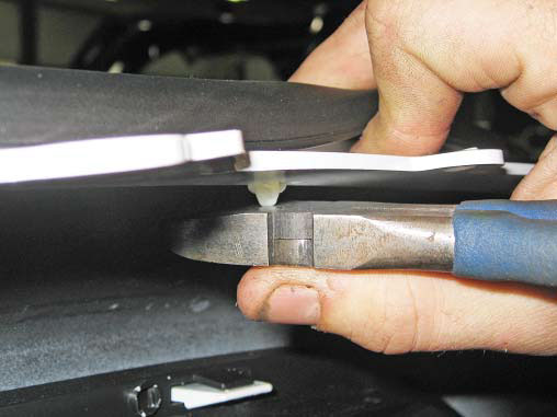
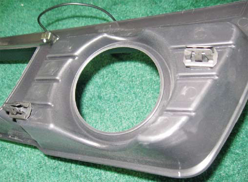
6. Remove the impact attenuator by bending up on the retaining clips while simultaneously pulling the attenuator away from the fascia. SAVE THE IMPACT ATTENUATOR FOR REINSTALLATION!
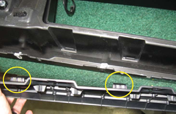
Close up of the retaining clip engagement
7. Remove the weatherstrip from the top of the fascia by pushing up from the bottom of the retaining clips.
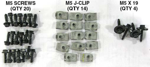
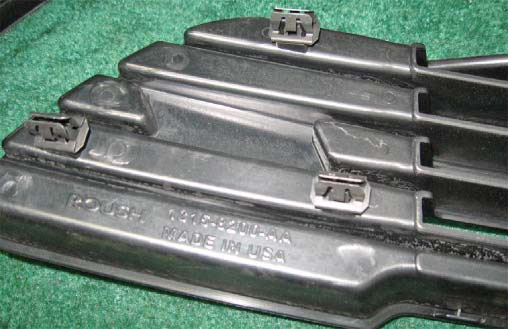
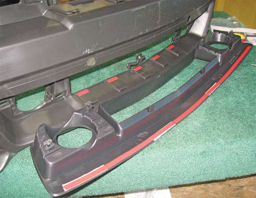
This concludes the OEM fascia disassembly. Please keep all hardware (screws, J-clips and push pins) for re-use in the new Roush fascia. OEM disassembly hardware to be re-used (without push pins)
ROUSH FASCIA ASSEMBLY
1. Insert the signal lens assembly into the appropriate (LH/RH) Roush bracket. Using three (3) self-tapping take-off screws (M5x16), fasten the signal assembly to the Roush bracket using a 7 mm socket. Repeat the same procedure for the opposite side lens.
2. Using a 7 mm socket, install the fog lamp using three (3) supplied M5 screws. Repeat the same procedure for the opposite side fog lamp.
NOTE: The fog lamp locator pins must be on the bottom-outboard corners. 3. Install the left fi ll panel to the Roush fascia using six (6) take-off self-tapping M5x16 screws. Repeat the same procedure for the opposite side fi ll panel.
4. Install two (2) M5 J-clips to the outer sides of the fascia, one per side. Only install the clip.
5. Using the six (6) self-tapping M5x16 fasteners with a 7 mm socket, install the signal assembly with bracket to the fi ll panel.
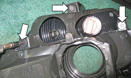
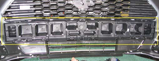
6. Install six (6) push clips onto the upper grille tabs. Three (3) are installed per side.
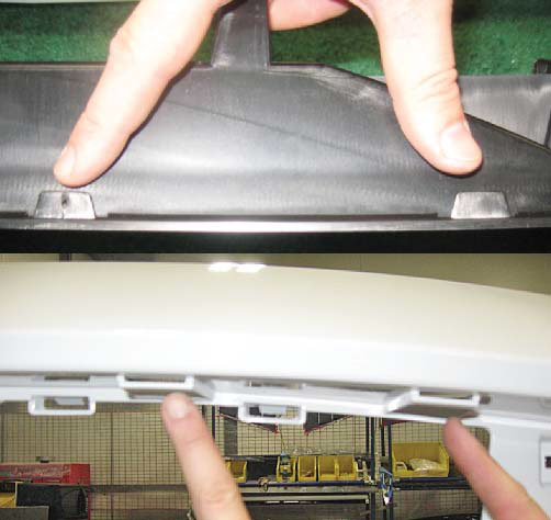
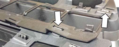
7. Install the upper grille to the Roush fascia by inserting the clips that were previously removed to their respective holes in the Roush fascia. Make sure that the guides (shown below) are fed into their respective slots as on the fascia as well.
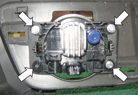
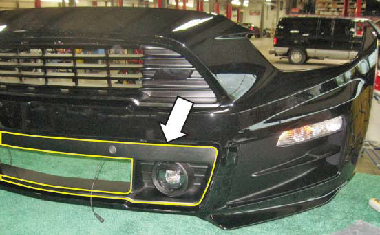
8. Install the park assist sensors. If the fascia is not equipped with park assist sensors, go to step 12.
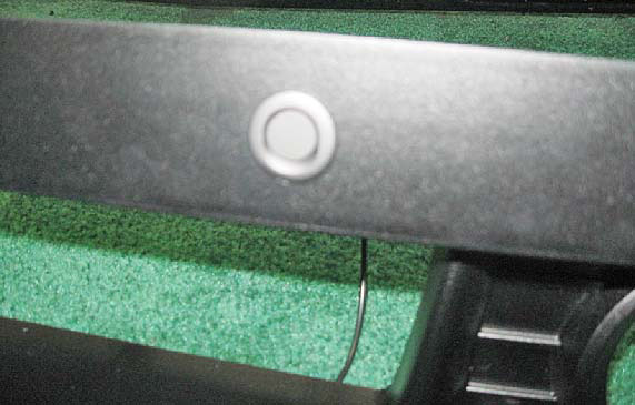
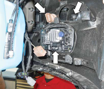
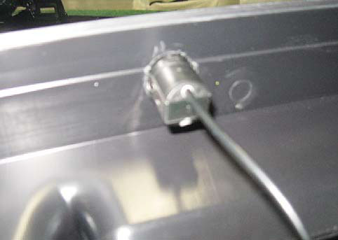
9. Drill an 18.8 mm (3/4") hole in the unmarked area on the top side of the lower grille and push the sensor through the fascia. The arrow on the sensor faces upward.
10. Push four (4) clips (20860) onto the lower grille, two (2) per side.
Right (passenger) side shown 11. Apply EX4015 tape across the top of the lower grille as shown below. Apply strips of tape to the fi ve (5) marks on the fascia as shown.
12. Peel the backing off of the tape and press the lower grille into place, seating the four (4) clips that retain the lower grille to the Roush fascia.
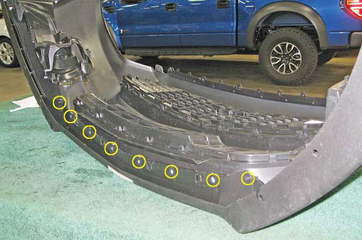
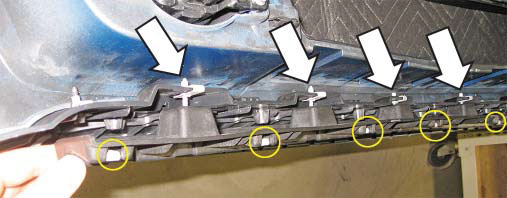
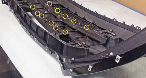
13. Use fi fteen (15) short J-clips along the bottom of the fascia, starting at the third position from the outside, leaving the last two (2) holes free at each end.
14. Install the front splitter to the fascia with fi fteen (15) M4.2 screws through the previously installed J-clips. Then install the sixteen (16) J-clips onto the splitter, as shown below. NOTE: For non-V8 GT performance pack-equipped vehicles, go to step 16.
Be sure to engage the tabs on the top side of the splitter to the fascia
Close up of the outer two (2) J-clips installed (right/ passenger side shown). Notice how they are installed in the opposite orientation from the rest (upside down) 15. For GT performance package-equipped vehicles only, the lower splitter assembly includes a spacer that fi ts between the splitter and the underbody aero panel. Install six (6) J-clips to this spacer, and fasten to the six (6) J-clips on the splitter.
16. Push two (2) push clips (20860) onto the fascia tabs as shown below. Repeat the same procedure for the opposite side as shown below.
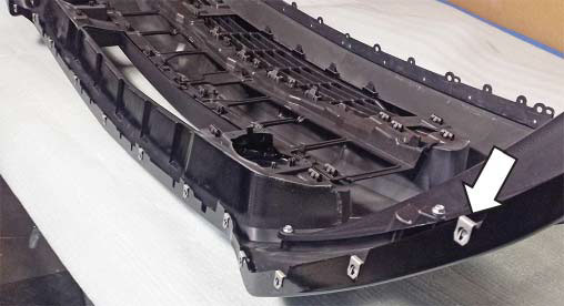
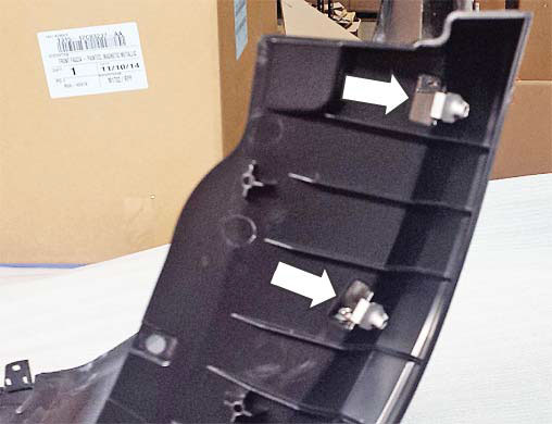
17. Line up and clip the impact attenuator bracket (1315-17E898) into position as shown below and press the impact attenuator onto the four (4) clips.
18. Push twelve (12) push clips (20860) onto the twelve (12) tabs that protrude through the energy absorber bracket.
19. Push the energy absorber into the energy absorber bracket. Make sure that the arrow is pointing up. Snap into position onto both the metal clips and the fascia tab as shown below.
Fascia tabs highlighted This concludes the Roush fascia assembly section.
FOG LAMP WIRING EXTENSION PROCEDURE
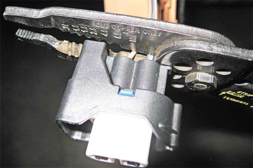
1. Begin by cutting the leads to the original connectors just before the connector. Make note of which wire belongs to which terminal (black/ ground to B/2 terminal). Do this to both left and right sides and remove about two (2) inches of the tape covering the wires.
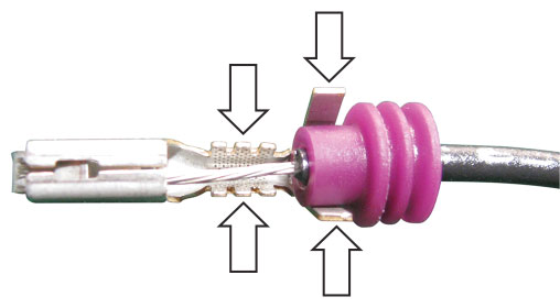
2. Slide the purple rubber seals over the insulation (ribbed end away from cut wire end) and then strip approximately 1/2" of insulation off the end of each wire using a pair of wire strippers in the 18-AWG setting.
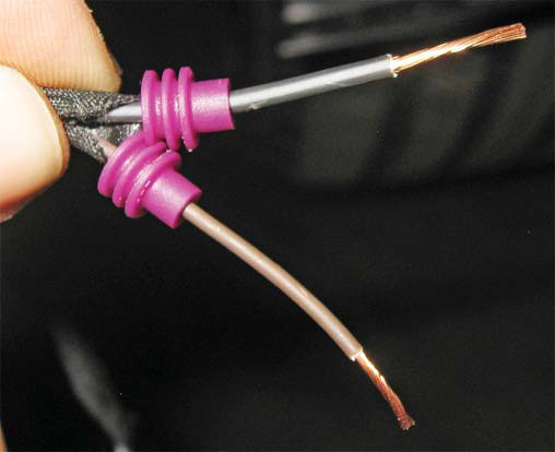
3. Slide the rubber seal to be fl ush with the end of the insulation and place it into the new terminal. Crimp the terminal onto the seal and then onto the wire.
ROUSH recommends soldering the terminal to the wire for improved conductivity and robustness – however this step may be skipped, if so desired, while maintaining functionality.
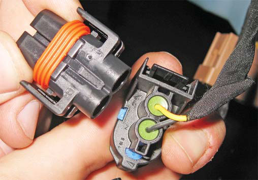
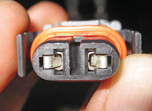
4. Insert the new terminals into the new connectors, being sure to seat them in the right position as well as the correct orientation as shown below. The terminals will click when correctly seated.
5. Split the wires apart in order to fi t the locking retainer onto the back of the new connector.
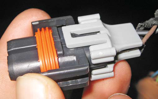
6. Connect the extension harness to the newly crafted connector. This concludes the fog lamp wiring extension harness section
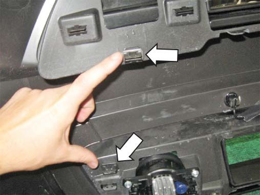
ROUSH FRONT FASCIA INSTALLATION 1. Install the ROUSH front fascia. Hook the upper fascia mounts onto the fi ve (5) dowel pins by the front of the inner bumper. The fascia should hang comfortably from the dowel pins.
2. Clip the corners of the front fascia into the body, pressing with your hands to seat all the clips. Do not hammer the fascia in with a soft fi st. Force isn’t necessary to seat the clips and if they aren’t aligned, the fascia clips may be damaged.
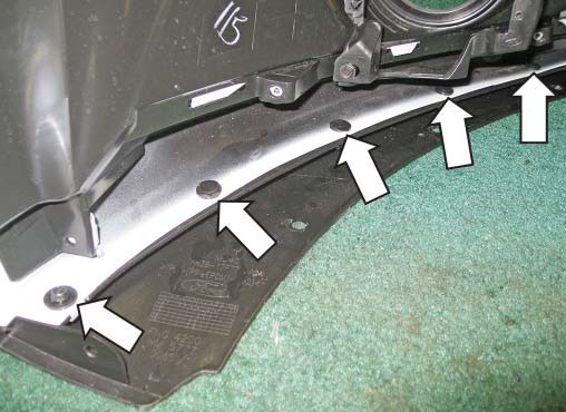
3. Install the seven (7) take-off screws that secure the fascia (reverse operation to step 2) on the top side of the fascia next to the locating/hang dowels. Install fi ve (5) 7 mm screws across the top and two (2) 5.5 mm screws in the corners by the headlamps.
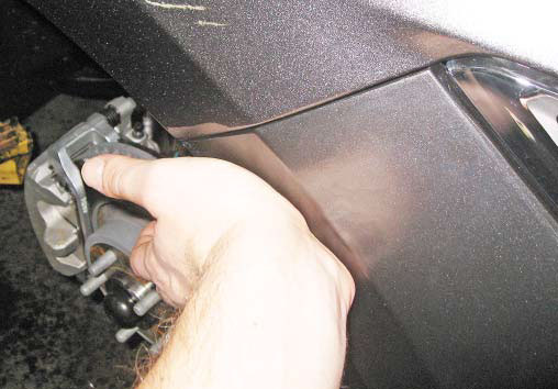
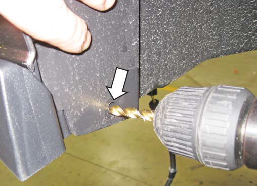
4. Line up the bottom corner of the fascia (by the wheel well) with the wheel well covering and drill the new hole in the splitter for the push pin with a 1/4" drill bit. Install the take-off push-pin into the new hole.
5. Connect the fog lamp extension harness and the turn signal harnesses. Use a zip tie or equivalent to fasten the extension harness slack against the vehicle.
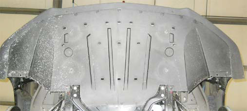
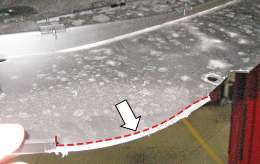
6. Non-GT performance (V8/V6/I4) equipped vehicles ONLY, modify the belly pan to achieve clearance in the corners to the new front splitter as shown below
Right (passenger) side belly pan
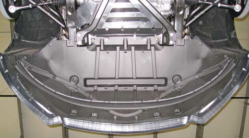
7. Reinstall the underbody aero panel reusing the take-off hardware from the OEM disassembly. Assembly is the reverse order of operations from disassembly.
8. Align the wheel well liner to the holes and reinstall the retaining clips.
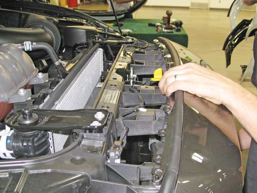
9. Reinstall the top radiator closeout in the reverse order. Re-use the take-off push pins to secure the closeout panel.
This concludes the Roush fascia installation procedure.
ROUSH FOG LAMP FUNCTIONAL TEST
1. Reconnect the negative battery cable.
2. Turn the ignition switch to the ON position.
3. Turn the head lamp switch clockwise so that the headlamps are ON and make sure the headlamps are in the low beam setting.
4. Turn the head lamp switch clockwise so that the headlamps are ON and ensure the headlamps are in the low beam setting. (NOTE: The fog lamps will not operate with the headlamps in the highbeam setting.) Toggle the fog lamp switch to the ON position and check to see if both fog lamps are illuminated.
5. Toggle the fog lamp switch to the OFF position. Check to see if the fog lamps are off. Congratulations!!! You have completed the installation of the ROUSH Performance Products, Front Fascia Kit. It is recommended that you save all parts removed from the vehicle during the installation of this kit