 FREE 1 to 3-Day Delivery on Orders $149+ Details
How to install a Roush Front Chin Splitter 2010-2012 Mustang
Installation Time
30 minutes
Tools Required
- Phillips Screw Driver
- Ratchet – 1/4" Drive
- 5.5 mm Socket – 1/4" Drive
- 8 mm Socket – 1/4" Drive
- 10 mm Box-end Wrench
- Drill
- 5/16" Drill Bit
- Torque Wrench – Lb-in, 1/4" Drive
- Masking Tape (Optional)

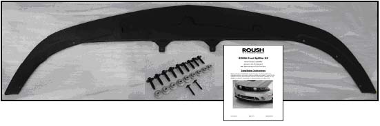
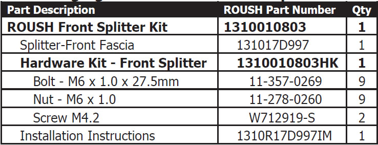
Shop Parts in this Guide
Installation
LIMIT OF LIABILITY STATEMENT
The information contained in this publication was accurate and in effect at the time the publication was approved for printing and is subject to change without notice or liability. ROUSH Performance Products (RPP) reserves the right to revise the information presented herein or to discontinue the production of parts described at any time.
SAFETY REQUIREMENTS
STOP! READ IMPORTANT SAFETY CAUTIONS AND WARNINGS BEFORE PROCEEDING.
IMPORTANT SAFETY NOTICE
Appropriate disassembly, assembly methods and procedures are essential to ensure the personal safety of the individual performing the kit installation. Improper installation due to the failure to correctly follow these instructions could cause personal injury or death. Read each step of the installation manual carefully before starting the actual installation.
Therefore, do not allow flames, sparks or flammable substances to come near the battery.
1. Always wear safety glasses for eye protection.
2. Place ignition switch in the OFF position.
3. Always apply the parking brake when working on a vehicle.
4. Chock the front and rear tires to prevent unexpected vehicle movement.
5. If working without a lift, always consult vehicle manual for correct lifting specifications.
6. Operate the engine only in well-ventilated areas to avoid exposure to carbon monoxide.
7. Do not smoke or use flammable items near or around the fuel system.
8. Use chemicals and cleaners in well-ventilated areas.
9. Batteries produce explosive gases, which can cause personal injury.
10. Keeps hands and any other objects away from the radiator fan blades.
11. Keep yourself and your clothing away from moving parts when the engine is running.
12. Do not wear loose clothing or jewelry that can get caught in rotating parts or scratch surface finishes.
13. Allow the engine, cooling system, brakes and exhaust to cool before working on a vehicle.
WORK SAFELY!
Perform this installation on a good clean level surface for maximum safety and with the engine turned off.
1. Using a 1/4” drive ratchet with a 5.5 mm socket, remove nine (9) screws from the lower close-out panel; one (1) at each wheel well splash shield, four (4) at the front fascia and three (3) at the rear edge of the close-out panel . Refer to Figure 1. Remove the lower close-out panel and set aside for reinstallation.
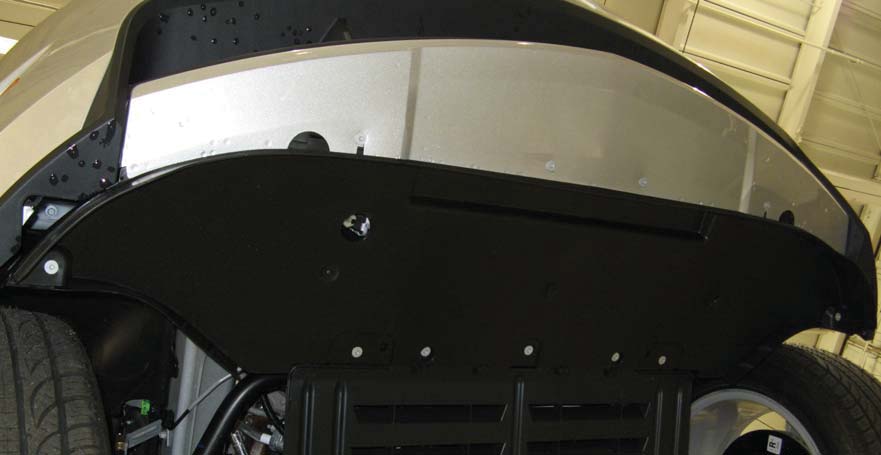
Figure 1
2. With an assistant holding the front splitter in position, install eight (8) M6 bolts (11-357-0269) and nuts (11-278-0260), as shown in Figures 2 and 3. Tighten and torque all nuts to 5 Nm (44 lb-in). Bolt hex-8 mm, nut-10 mm.
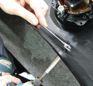
Figure 2
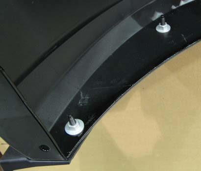
Figure 3
3. With the Front Splitter securely fastened to the fascia, locate the dimple at the center of the part and slowly drill a 5/16” hole through the splitter and lower fascia. Refer to Figure 4. Be careful not to allow the drill bit to contact the upper surface of the fascia, as shown in Figure 5. Wrap the drill bit with masking tape, 1/2” from the tip of the drill bit, to act as a drill stop.
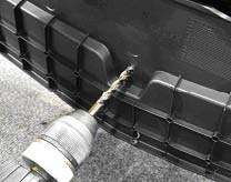
Figure 4
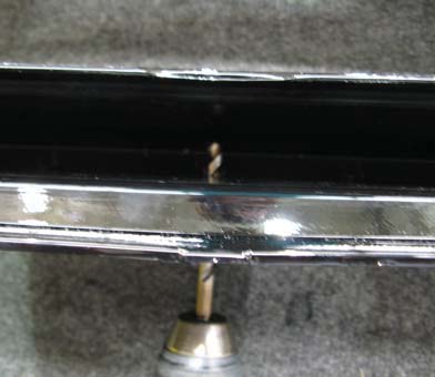
Figure 5
4. Install one (1) bolt (11-357-0269) and nut (11-278-0260) into the drilled hole at the center of the Splitter. Tighten and torque the nut to 5 Nm (44 lb-in). Refer to Figure 6.
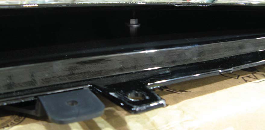
Figure 6
5. Using a 1/4” drive ratchet with a 5.5 mm socket, reinstall the lower closeout panel using the nine (9) hex head screws previously removed in Step 1. Two (2) at the wheel well splash shields, three (3) at the sub frame and four (4) at the front fascia. Refer to Figure 7.
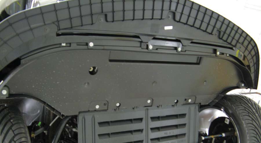
Figure 7
6. Install two (2) Phillips head screws (W712919-S) at the rear of the Splitter to the clip nuts on the close out panel, as shown in Figure 8.
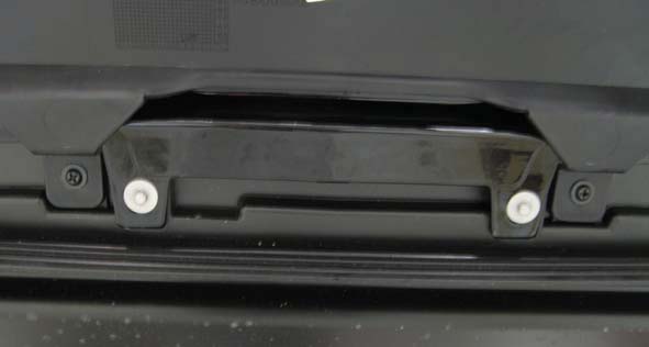
Figure 8
Congratulations!!! You have completed the installation of the ROUSH Performance Products, Front Splitter Kit. It is recommended that you save all parts removed from your vehicle during the installation of this kit.
