 FREE 1 to 3-Day Delivery on Orders $149+ Details
SCT EGT Sensor Kit Installation Guide
Installation
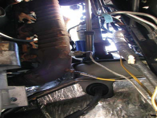
1. Locate the exhaust manifold on the driver’s side of the vehicle. The area of the manifold to be drilled and tapped is located at the rear of the manifold near the driveline of the vehicle. (Refer to image below)
2. Use a generous amount of heavy grease on the drill bit and tap to capture any metal shavings or contaminates left as a result of the drilling and tapping process. Always use a small magnet after the process to ensure that you have retrieved any metal shavings prior to installation of the thermocouple.
3. Drill a 5/16” hole in the manifold. Using a 1/8” National Pipe Tap (NPT), which can be purchased at any hardware store, tap the hole. Be sure to follow the instructions included with the tap. The tap will be tapered and you want to tap the hole only until the threads of the tap are slightly deeper than the inside of the manifold. Be careful not to tap too deeply into the manifold as the fitting on the thermocouple will have to be screwed in deeply.
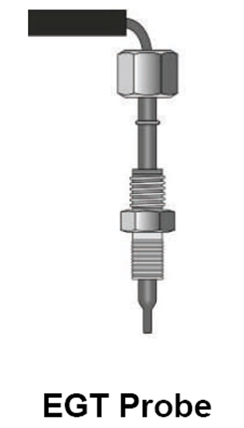
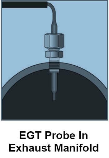
4. Once the drilling and tapping are complete, check to make sure there are no metal shavings in the manifold. If you see shavings or contaminates, remove them before inserting the thermocouple. Install the fitting by screwing the tapered end of the fitting into the manifold. The tip of the fitting should be flush with the inside of the exhaust path, but not any deeper. Tighten the fitting with a small wrench or socket, but be sure not to over-torque the fitting. Insert the probe into the fitting so that the tip is in the center of the exhaust flow path. Tighten the top nut on the fitting just tight enough to keep the thermocouple firmly in position.
5. Locate a place for the EGT Amplifier Box. This can be an place you choose, but it should be kept away from any heat source and any sources of extreme vibration. Do not place on or near the engine. Use the supplied Velcro strips to secure the EGT Amplifier Box to the interior or firewall.
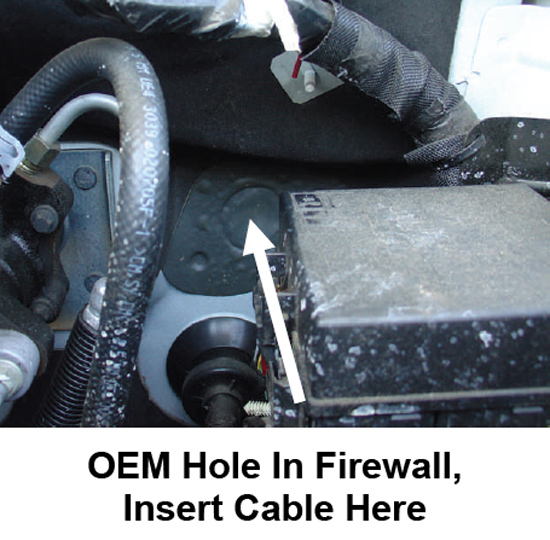
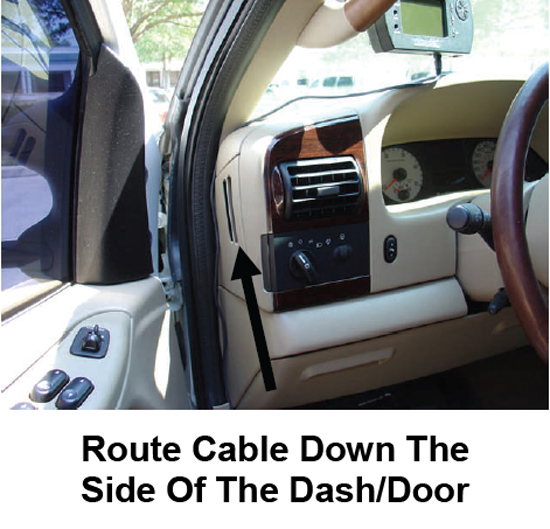
6. You will need to run the EGT Sensor Cable or the EGT Analog Cable through the firewall of the vehicle, depending upon whether you mounted the EGT Amplifier Box in the interior or exterior. Please note which cable you need to insert through the firewall prior to opening the OEM hole in the firewall. Use aluminum tape or equivalent to cover the OEM hole after the cable assembly has been routed into the interior. (Refer to image below) The Analog Cable can be easily inserted between the driver’s door sill and the dash to keep it hidden and secured. You may also want to perform some type of custom installation or routing of the cable based on your individual needs.
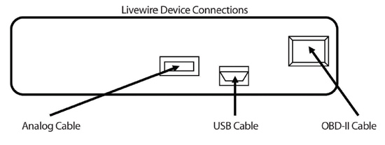
7. Once the cable routing is complete, plug the EGT Sensor Cable with two prong connector into the Amplifier Box along with one end of the Analog Cable. Plug the opposite end of the Analog Cable into the Livewire device.
How to Set Up Your SCT EGT Sensor Kit
1. This procedure will show you how to setup your Livewire to display/monitor your SCT Livewire EGT Sensor Kit. Using the jog wheel, scroll to the Performance Data Menus and press the jog wheel.

2. Scroll to the External Input icon and press the jog wheel. After reading the next screen that is displayed, press the jog wheel.

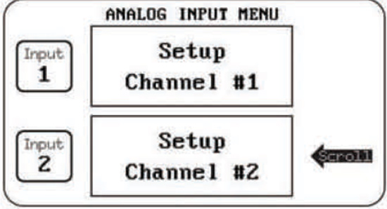
3. Using the jog wheel, scroll down to the setup Channel 2 selection and press the jog wheel.
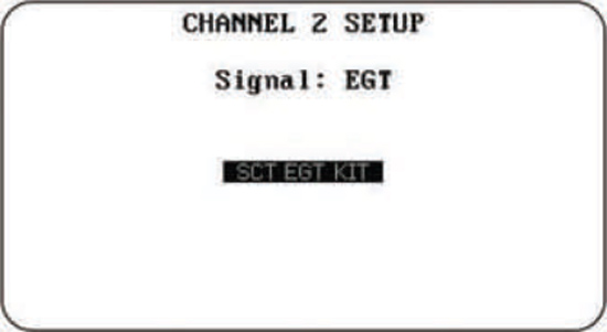
4. Once the Channel 2 Setup screen is displayed, scroll to the EGT selection and press the jog wheel.
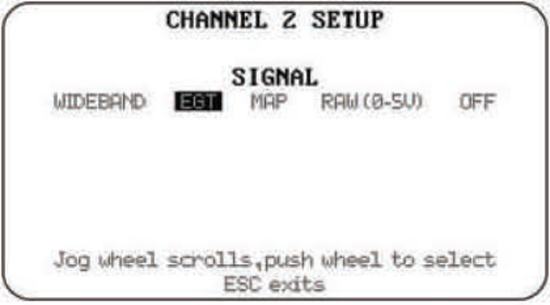
5. Scroll to the "SCT EGT KIT" selection and press the jog wheel. When finished, press the ESC button to return to the main menu.
Installation instructions provided by SCT
