 FREE 1 to 3-Day Delivery on Orders $149+ Details
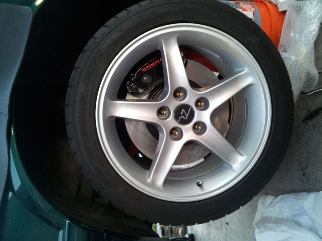
How To Install a Replacement Front Rotor on your 1987-1993 5.0L Mustang
Installation Time
1 hours
Tools Required
- One jack and two jack stands.
- One13mm wrench and one 15mm wrench.
- One socket wrench with a 13mm, 15mm, and 29mm socket.
- Socket extension(s).
- Torque wrench is advisable, but not necessary to torque the lug nuts.
- Pry bar (you may or may not need this).
- 50 torqx star bit (for the caliper bolts or you may use a socket, but this is preferable).
- A bucket to place the caliper on after it’s off.
- Flat head screwdriver.
- Needle nose pliers.
- Bearing seal driver kit.
- Brake piston compressor tool.
- Grease for bearings.

Shop Parts in this Guide
NOTES:
Before doing this job, PLEASE READ THROUGH THIS ENTIRE GUIDE. Some extra tools and research may be needed to before doing this.
This is not a complete guide; however it will give you a very good idea of what to do. I was doing a SN95 Cobra upgrade, so I decided to help others out and show them what is needed to do this job. It’s not hard, but you need a few tools to make it easy. I strongly advise if you have never done a job like this before, please get a buddy who has to help you.
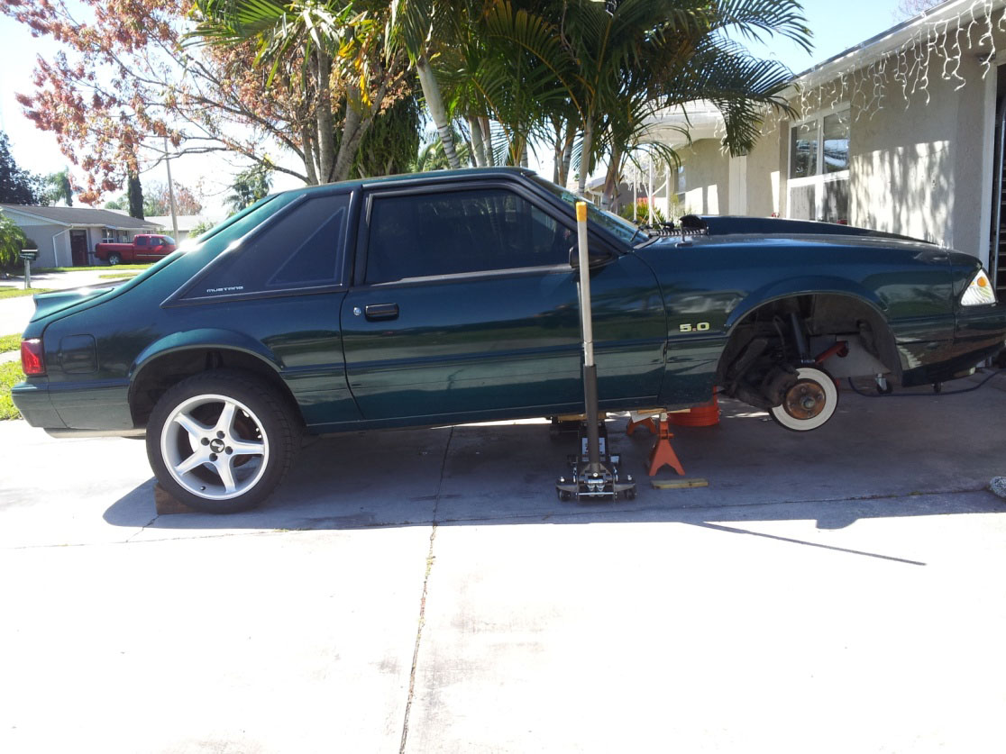
1. Jack up the car and safely put the car on jack stands.
2. Put the car in park (or 1st gear for manual transmission) and put the E-brake on and something behind the back wheels to ensure the car does not roll.
3. Remove front wheel(s).
4. Take a 50 torqx star bit to loosen the two caliper bolts.
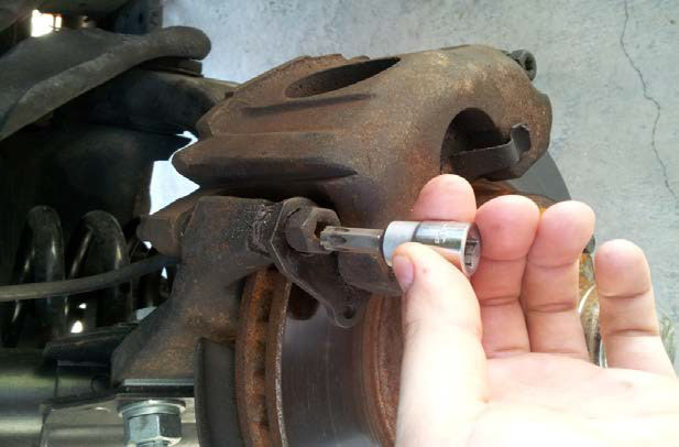
5. The caliper should pull right off after the two bolts are out (pull up and toward the rear).
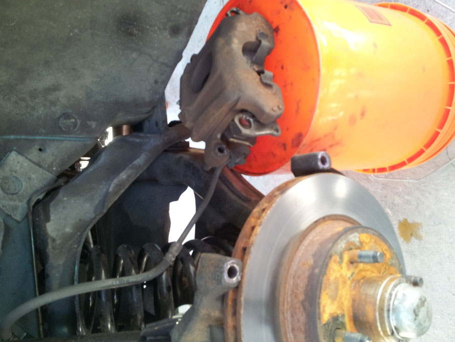
6. Place the caliper on a bucket (or whatever else you have).
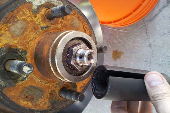
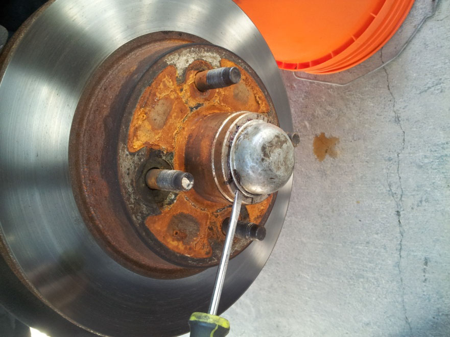
7. Take a flathead screwdriver to take off genteelly the dust cap.

8. Take a pair of needle nose pliers to take off the cotter pin under the center cap.
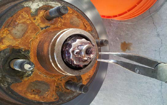
9. The cap that the cotter pin was on should pull right off.

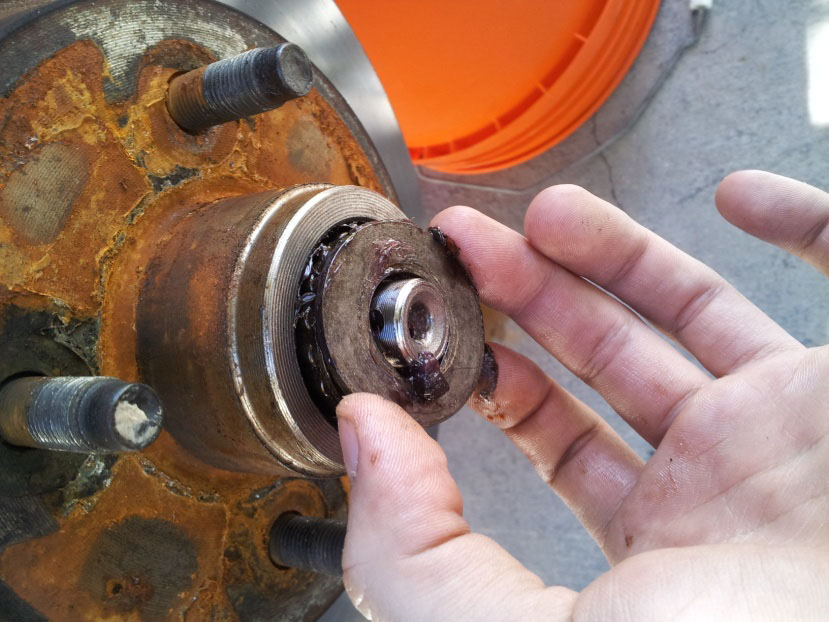
10. Take off the center nut with a 29mm socket.
11. Once the center nut is off, there is a washer beneath it that should come right out.
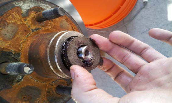
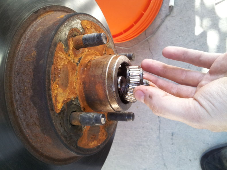
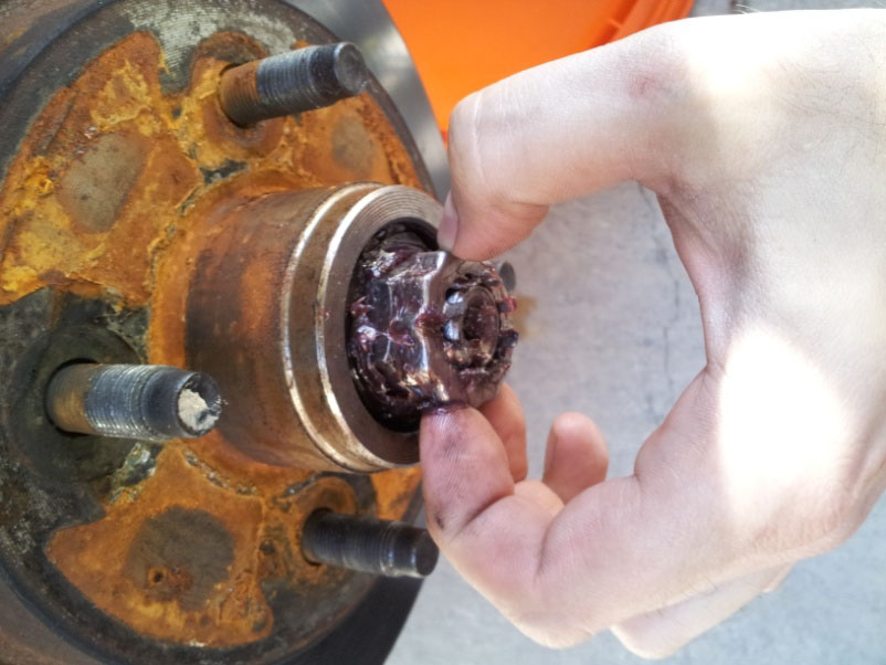
12. Now take out the bearing.
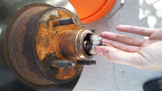
13. The rotor should now come right out!!!
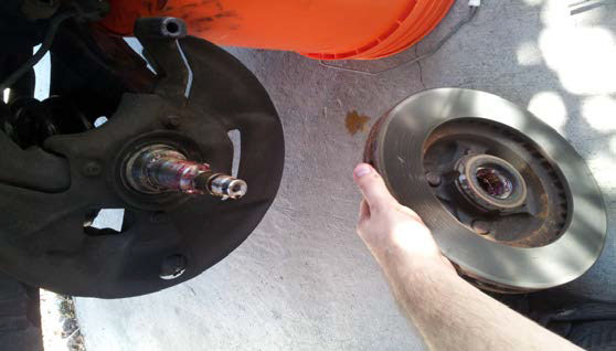
***Note: This is the point where I started to do the SN95 Cobra upgrade I told you about earlier, so I am out of pictures. The rest is easy, but if you do not feel comfortable, please ask a buddy who can assist you. The whole point of me doing this was to show you what is needed to do this job. I realize it’s not complete with as many pictures that I would like, but it’s better than nothing. I encourage one of you to take it to the next level and make a better write up for others.
14. Now take the new rotor and spray it with brake cleaner.
15. Once it’s dry take some grease and pack the new bearings with it (be generous).
16. Place one of the new bearings in the new rotor.
17. Take your bearing seal driver kit, the new bearing seal, and tap the new bearing seal into place (above the bearing on the rotor) (see the last picture of the back of the rotor).
18. Be sure the seal is even and tight.
19. Now take the new rotor and put it back on the spindle.
20. Now put everything back on in reverse order with the new bearings and new hardware.
21. Once the new rotor is clean, has the new barring, and is greased, put the rotor back on the spindle.
22. Now take the new bearing for the front of the rotor, pack it with grease, and put that in first. (yes these are the same pictures from before pretend they are new parts)
23. Put your washer back on above the bearing.
24. Put the center nut on next and tighten it with your 29mm socket.
NOTE: I do not remember how tight you should tighten this. Please do some of your research and figure it out. I do not have the torque specs, too tight will damage the bearing and too loose can pop the wheel off. PLEASE double check!

25. Next, put your cotter pin cap back on.
26. Put your NEW cotter pin in (do not reuses your old one, and get a GOOD cotter pin).

27. Finally, put your dust cap back on. You can tap it lightly like a drum, or use a small piece of wood to tap it in the center. Be gentle and forget about the screw driver in the picture.
28. Now it’s time to do the calipers. Take the old brake pads off. The outer one should slide down, and the one in the piston pulls out.
29. Take a brake piston compressor to push back the caliper piston.
30. Take the new brake pads and lube with brake grease wherever metal to metal touches.
31. Put the new pads on the calipers.
32. Now put the calipers back on the spindle, take the two caliper bolts from earlier and put some grease on them, put the two bolts back on the calipers, and tighten them.
33. it’s always a good idea to bleed the brakes, but if you used the piston compression tool not 100% necessary at the moment (but do it anyways).
34. Put the wheels back on the car and torque them. Personally, I torque my car to 100ft pounds and have never had a problem HOWEVER, always use torque specs that YOU trust.
35. Safely put the car back on the ground.
36. Before you take it for a test drive be sure that you stiffen up the pedal by pushing the brake pedal a few times. Always be careful when test driving since your brakes are new and you are… well breaking them in. Always consult the manufacture of the pads you bought for proper brake in procedure for the new pads.
37. You are now done! Yay!
Installation Instructions Written by AmericanMuscle Customer Joseph DeCresie 4.22.2014
