 FREE 1 to 3-Day Delivery on Orders $149+ Details
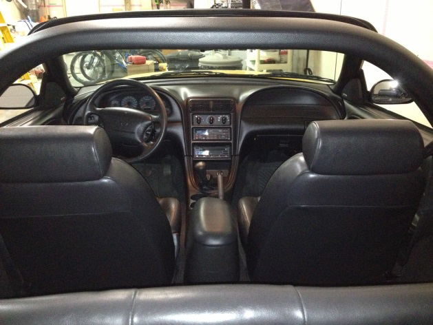
How To Install a MMD Convertible Styling Bar for your 1994-2004 GT, V6, Cobra Mustang
Installation Time
4 hours
Tools Required
- Electric Drill
- 1” Forstner Bit (Hole Saw)
- 1 3/8” Hole Saw (manual calls for 1 ¾”)
- 1/8”, 3/8” & ¾” Drill Bits
- Rivet Gun
- Trim Removal Tool
- Needle nose pliers (bent-head version is ideal)
- Ratchet & Extensions
- 7mm & 10mm Sockets
- ¼” Allen Wrench
- Center Punch & Hammer
- Construction Knife
- Flat file
- Dremel Saw-Max (optional)
- Small-tip Felt
- Plastic Garbage Bag
- Vacuum cleaner
Step 1: Back Seat Bottom Removal
• Hint: VERY carefully so as not to scratch the seating material, slide the tip of the screwdriver along the underside of the seat – when you reach an obstacle, you will have found the catch. Pull the screwdriver out slightly, move another ¾” towards the obstacle so as to be over top of it, and then simply push in slightly.
• Using a larger flat head screwdriver, locate the seat retaining catch. This is a spring-loaded catch that has a release tab when pushed slightly (about 1/8”) towards the back of the car.
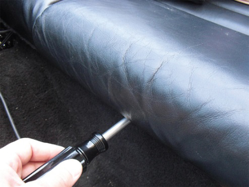
• There are two latches, each approximately 1/3 of the way under the seat.
Step 2: Back Seat Back Rest Removal
• Once you lift the Seat Bottom up and out of the way, two 10mm bolts will be visible. Simply remove both bolts.
• Lift the seat back upwards until the two metal ‘tabs’ clear the vehicle body.
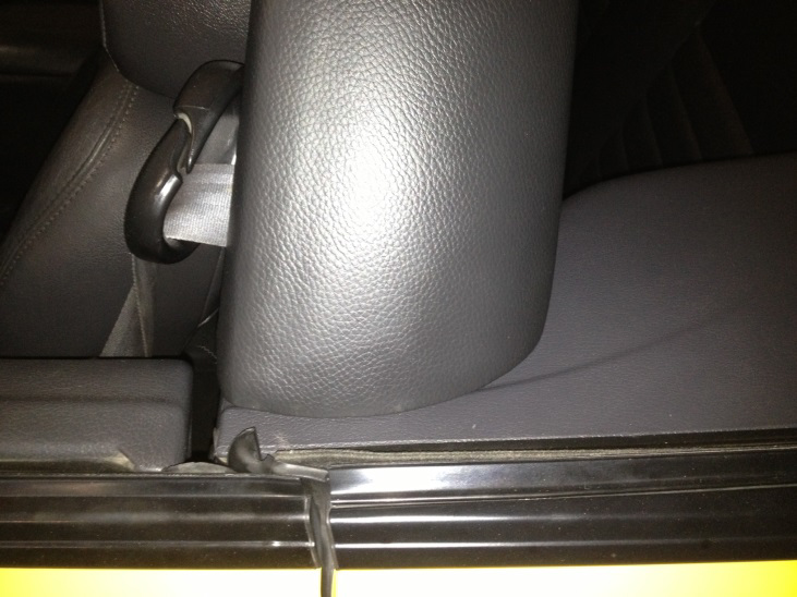
• Hint: you will have to delicately work around the back seatbelts – be careful so as not to damage any cloth/leather.
Step 3: Seat Belt Removal
• In order to completely remove the panels, the seatbelt needs to be removed from the vehicle down by the door sill. Removing the bolt now will make things easier.
• Using the T-50 Torx Bit and a ratchet, simply remove the attachment bolt.
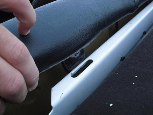
Step 4: Rocker Sill Cover Removal
• The rear side panels both have tab edges that are concealed by the Rocker Sill Covers. To properly remove the panels, the Sill Covers need to be slightly lifted up.
• Carefully grasp the sides of the Sill Cover and pull upwards – they are held in place by pressure clips.
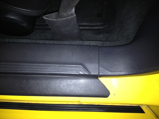
• Hint: You do not have to completely remove the entire Sill Cover – only about 1/3 needs to be lifted up in order to clear access for panel removal.
• Hint: While working on the car, keep a watchful eye on the Sill Covers so they are not pressed back into position.
Step 5: Pin Removal (5 pins per side)
• To remove each of the two back side panels, you will need to locate and pop-out the 5 factory pins that secure each panel.
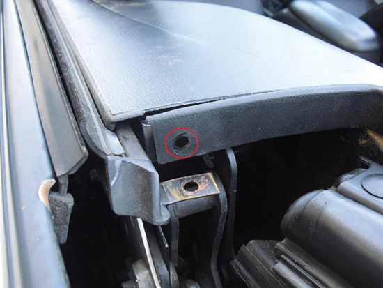
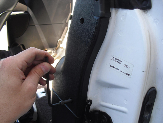
a. Single pin at rear of panel. (located above the convertible top framework/mechanisms, best viewed from the rear of vehicle, facing the front)
i. Using a trim removal tool (aka: pin popper), carefully remove the pin.
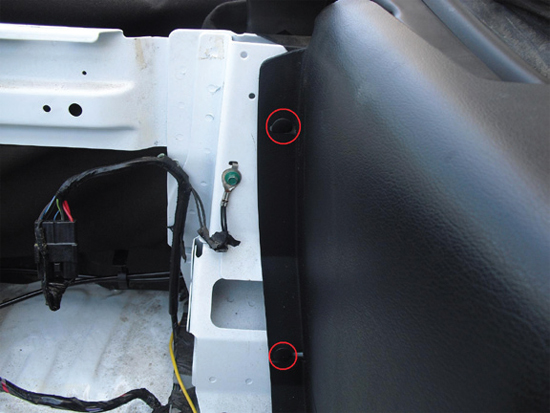
b. Remove the two pins at the back/side that were hidden by the seat back.
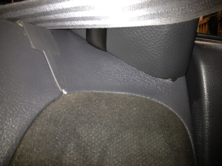
c. Very carefully remove the two small pins holding the rubber seal to the panel (at the top of the B-pillar)
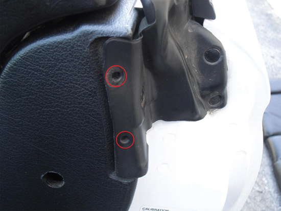
• Hint: Using a bent-nose needle nose plier can be helpful in removing the larger pins once they are loosened.
Step 6: Panel Removal
• Now that all pins are removed and the Rocker Sill Cover is lifted up far enough to clear, the side panel should be free to be loosened.
• The MMD installation manual makes reference to removing the UPPER speaker grille covers at this time; removing this grille allows a larger hole to pass the seatbelt through
• HINT: ONLY THE UPPER GRILLE is removable!!! It is secured by several spring clips – it may be easier to apply pressure by hand from the back of the panel once it is loosened from the vehicle.
• The panels have 2 spring/pressure clips & alignment pints that affix it to the b-pillar; pulling the panel slightly towards the front of the vehicle will unclip them, allowing the panel to be removed.
• Thread the bottom of the seatbelt through the open hole while removing the panel.
Step 7: Templates
• The included templates are difficult to work with – be aware of this. It will be helpful to have a second person to assist in marking while the first person holds each template in position.
• There are four templates: 1. Driver side top hole (to insert the styling bar)
2. Passenger side top hole (to insert the styling bar)
3. Driver side B-pillar holes (to access securing bolts)
4. Passenger side B-pillar holes (access securing bolts)
1. Driver & Passenger Side top holes a. These are the most difficult to position. The template is not entirely to scale, and during my installation, the holes were too low – I had to manually enlarge the top opening after the panels were reinstalled.
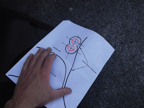
b. Use the template’s speaker cover and front edge lines to match up the positioning; it may be helpful to slightly fold along the front edge line of the paper to help landmark.
c. Hint: the top edge line of the speaker cover refers to the grille edge (not the inner edge).
d. When positioning the paper, pay particular attention to the ‘step’ in the top of the panel’s plastic – the hole should be very near this step.
e. Once the template is in position, have the 2nd person use the punch/awl to put a mark through the paper, into the plastic – this will give a reference point to work from.
f. Position the side panel in such a way that it is secured and will not move or slide away – a 2nd person to help hold is a good idea.
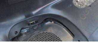
g. HINT: At this point, use the 1 3/8” hole saw as a REFERENCE ONLY to verify the positioning of the top hole location; refer to the picture to note the proximity of the (future) hole edge to the step of the side panel. (Now is an easy time to shift the hole, if needed.)
h. Using the 1/8” drill, locate the punch/awl marks and carefully drill the 2 holes on each panel; these are the pilot holes for the next step.
i. Using the 1 3/8” hole saw, enlarge the pilot holes you just made. Note: the holes do overlap each other – this is good.
j. Using a file, knife or other cutting device, smooth-out the intersection points of the two holes, creating an oval opening.
k. HINT: I used a Dremel Saw-Max to enlarge the opening.
2. Driver & Passenger Side Panel B-Pillar (front) holes
a. This step is critical, as the template holes and the included brackets DID NOT MATCH UP!! As a result, the upper hole will be accurate, but the lower hole may not coincide with the bracket, making bolt installation nearly impossible.
b. HINT: The installation kit comes with 4x 1” pop-in hole covers. It is a good idea to use the 1” Forstner bit (or hole saw) and cut a test hole into an old piece of junk wood/plastic/etc. for the purpose of testing the cover’s fit.
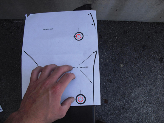
c. Before starting, measure the included bracket – determine the exact width between the centers of each hole; note the measurement.
d. On the template, use the upper hole as the starting point. Confirm that the distance between the holes on the template is the SAME distance as the actual bracket; if they do NOT coincide, re-label the template so the lower mark is the same distance as the bracket measurement.
e. Using the appropriate left-or-right template, position it on the panel. As before, it may be helpful to make a fold along the edge line to help landmark the position.
f. HINT: Use a pair of old screws and place them through the two paper & panel holes to help line-up and position the template.
g. Using a punch/awl, mark both holes through the paper.
h. Once more, confirm that the marks on the panel are the SAME DISTANCE apart as the bolt holes on the bracket.
i. Using the 1/8” drill, locate the punch/awl marks and carefully drill the 2 holes on each panel; these are the pilot holes for the next step.
j. Using a 1” Forstner bit, VERY CAREFULLY and very gently enlarge the pilot holes.
k. HINT: the MMD manual calls for a 1” Hole Saw – while a valid tool, hole saws tend to leave jagged-edge, uneven holes; it may be more difficult to conceal the holes thereafter. (The Forstner bit leaves a nearly perfect opening.)
Step 8: Side panel modification
• The side panels each have two sets of alignment pins/spring clips to secure the panel to the B-pillar; the upper one needs to be removed.
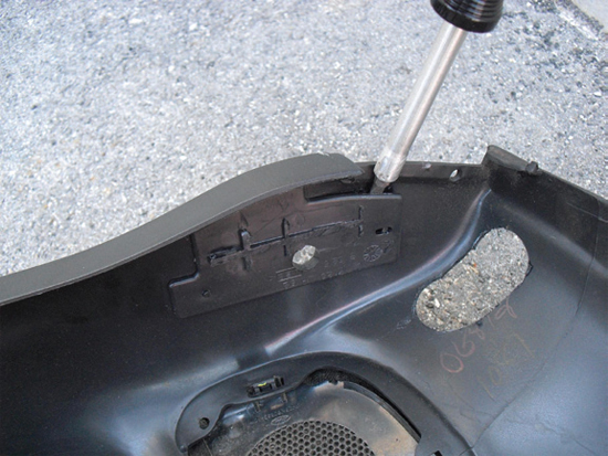
• Simply & carefully pry it away. Be careful not to pry too hard with a screwdriver tip, so as to avoid the possibility of damaging/discoloring the front of the side panel.
• HINT: the entire plastic mounting clip needs to be removed; cutting away only a portion of it will interfere with the styling bar later.
Step 9: Speaker Removal
• In order to gain access to back (inside) of the B-pillar location, the speaker pods have to be removed.
• HINT: they do not need to be unplugged.
• Contrary to the MMD manual, there were 3x 7mm bolts that secured each pod. (The 3rd bolt was attached to a flat L-bracket that supported the underside of each speaker pod; this bolt is near the back seat spring clip location, and easily removed.)
Step 10: Inner Quarter Panel Covers
• Access to the inner B-pillar is concealed behind a plastic quarter panel cover.
• This cover has a built-in alignment pin, and is further secured by a black sealant.
• HINT: this sealant will stick to you and anything it comes in contact with – be careful of your clothing, tools and vehicle interior.
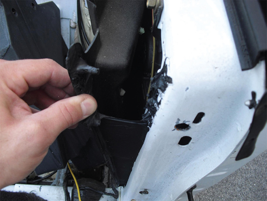
• Carefully pry the top of the cover out, and then pull the cover back – it does not need to be fully removed.
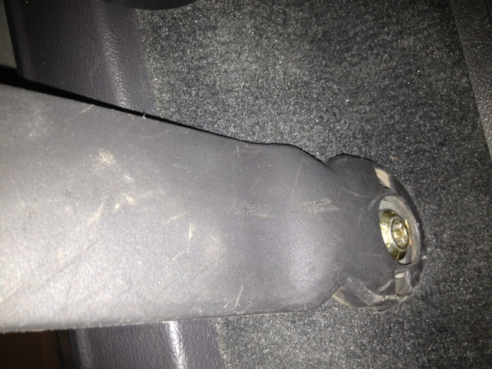
Step 11: Bracket positioning
• The Styling Bar sits atop of the B-Pillar, and sandwiches the vehicle body between the bar and a bracket.
• There are two brackets, each marked “R” and “L”.
• HINT: “L” is the driver side, “R” is the passenger side.
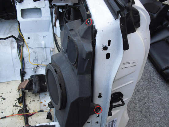
• The brackets have a pair of nuts welded on the back each. These nuts are off-set to one side on each bracket. Use the opposite side bracket on each side of the vehicle to mark the holes that need to be drilled through the body. (Use the “R” bracket on the driver side, as shown in the picture.)
• HINT: the edge of bracket will sit almost exactly along the inner edge of the B-pillar.
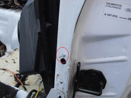
• The installation kit includes a pair of pop-rivets. Use one of the rivets, insert it through the small, lower hole of the bracket, and then insert it into the small factory hole on the B-pillar – this will help position and align the bracket to the B-pillar.
• HINT: the bracket sits quite high on the B-pillar. Refer to the pictures to get a good sense of position in relation to the other holes in the B-pillar.
• Using either a punch, awl or small-tip felt, position the bracket and then place a mark on the vehicle through the nut holes. This will give a nearly perfect mark through which to drill the pilot holes.
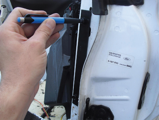
• HINT: drilling these holes generates a LOT of metal shavings that are difficult to clean/vacuum after; using a plastic garbage bag, cut one side open and position it so that it will act as a catch for most of the shavings.
• Using the 1/8” drill, locate the punch/awl/felt marks and carefully drill the 2 holes on each panel; these are the pilot holes for the next step.
• HINT: the MMD Installation manual recommends to go directly to the ¾” hole next – however, it will be easier to use a 3/8” drill bit as an intermediary step, then the ¾” hole after that.
Step 12: Bracket Installation
• Now that the holes are drilled, it is time to place each bracket inside the quarter panel/B-pillar and fasten it.
• HINT: have the pop rivet gun within reach and ready to go for these next steps.
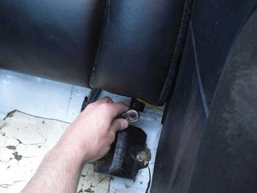
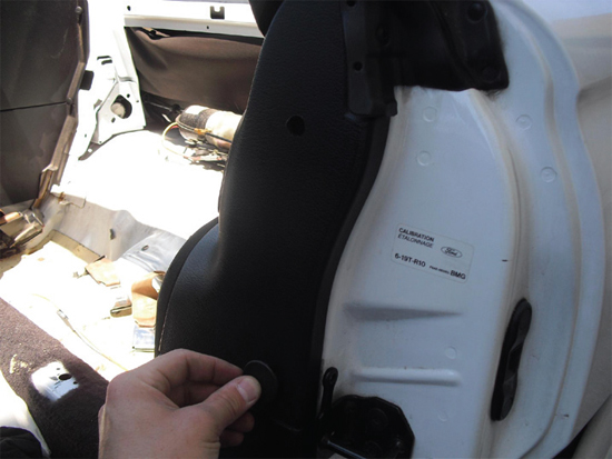
• For the driver side, use the “L” bracket. With the nuts facing toward the back of the vehicle, carefully place the bracket inside the quarter panel and on the back of the B-pillar.
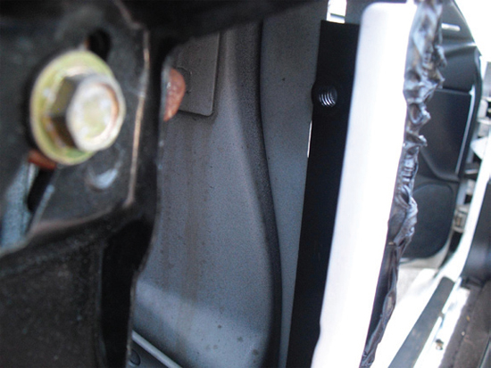
• Note: picture is a view to inside the quarter panel; the back of the B-pillar is shown.
Use the pop rivet to help align the bracket; insert the rivet (as shown in the picture) from the outside of the B-pillar, and slip the bracket over top of the rivet from the inside.
• The bracket nuts should be centered and clearly visible through each of the .” holes.
• HINT: the ¾” holes are larger than the actual bracket nuts – this is so that the brackets can slightly move on final bar installation, providing a margin of error.
• While pressing the bracket tight against the inside of the B-pillar, fasten the pop rivet.
• HINT: the brackets may move/swivel slightly after the (single) pop rivet is installed – this is perfectly normal, and provides some ‘wiggle room’ for when the bar is placed.
Step 13: Panel re-installation
• It is now time to replace the following:
• Quarter Panel Cover
• Speaker Pod
• Side Panel
• Simply reverse the steps above (Step 6, 9 & 10 in particular)
• HINTS: • When re-installing the Quarter Panel Cover, use the built-in pin to help align the cover to the vehicle.
• When re-installing the speaker pod, install the top bolt first (it will help with the alignment of the pod and the remaining bolts)
• When re-installing the side panel:
Remember to feed the seat belt through
Use the lower, remaining alignment pin/spring clip to properly landmark and position the panel against the B-pillar
Ensure that the rocker sill cover goes OVER TOP of the side panel
Keep a watchful eye on the rubber gasket that it does not get stuck underneath the side panel
Use the pin hole at the top, back of the side panel (above the power top mechanism) as an alignment reference point
Use the side panel side pin holes (that get covered by the seat back) as alignment reference points
Take caution not to flex the entire panel too much – they can become brittle over time and crack; simply re-position the panel a few times as needed and it will click nicely into place.
DO NOT re-insert the panel pins at this time; in case modifications are required, you may have to re-remove the panel(s).
• Note: the two holes on the front of the panel should coincide perfectly with the bracket nuts.
Step 14: Styling Bar Installation/Placement
• Now that the side panels are fitted back in place, it is time to test-fit the styling bar.
• HINT: the styling bar is quite forgiving in the event that the top hole may seem somewhat large; it should cover the oversized hole completely.
• Firmly grasp the bar, and take EXTREME caution so as not to scratch your vehicle!!!
• Insert the bar ends into the newly-cut holes.
• HINTS: o You may have to insert each side a little bit at a time and move back and forth as you seat the bar.
o As this is not a true “Roll Bar”, it WILL flex a little – if the initial insertion fit is extremely tight, try flexing the bar a little:
o Insert one side, then try ‘compressing’ the entire a little (like pinching it) to determine if the other side can slip into place.
o Note: As a customer, I found that the top 1 3/8” hole was not up high enough/near the step in the side panel; I had to remove the bar and enlarge the hole more so as to be able to have the bar line up and fit inside the opening.
• With a little flexing and fitting, the bar will move into place.
Step 15: Styling Bar Bolts
• The installation kit includes 4x Hex-head bolts and 4x washer.
• Once the Styling Bar is properly placed, you will be able to see the bracket nut holes through the styling bar bolt holes; if not, move the bracket up & down a little to get them to line up properly.
• Insert the bolts through the styling bar bolt holes and thread them into bracket nuts – remember the washer.
• Do not tighten all the bolts yet – some fitting and adjusting will be needed.
Step 16: Replacing all the panel pins
• Once all the bolts are in place, leave the bar slightly up/raised to ensure that little pressure is placed on the side panel.
• If you are satisfied that everything fits together well, replace the 5 panel pins that were removed in Step 5.
Step 16: Styling Bar Leveling
• While the 4 bolts are still somewhat loose, position the styling bar into place so that it has a good fit against the top of the side panels.
• Looking from the back of the vehicle, use the top of the windshield frame as a visual reference to ensure that the style bar is level to the vehicle. Gently nudge the bar up/down on either side as needed
• HINT: this might take several attempts to get the bar perfectly level to the car.
• Checking for a level bar against good coverage of the holes, tighten down the bolts. You may have to go back several times on each side to ensure each bolt is properly tightened
Step 17: Replacing the Seats
• Simply reverse Step 1 & 2
Step 18: Re-attaching the seatbelt
• Simply reverse Step 3
Step 19: Replacing the Rocker Sill Cover
• Simply reverse Step 4
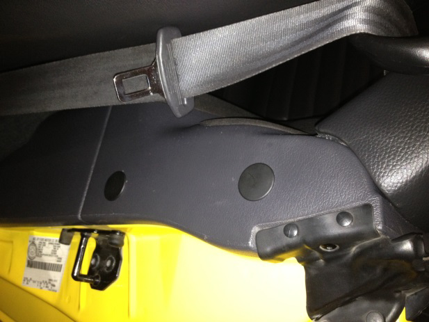
Step 20: Bolt Hole Covers
• The Styling Bar installation kit comes with 4 click-in panel covers.
• Simply click each of the covers over top of the 4 bolt holes.
Final Check
• As always, ensure that no extra parts are left over; if so, determine where they came from!
• Double-check to ensure that your seatbelt is fastened and secure.
• Ensure that the styling bar is firmly attached and solid.
• Using your vacuum cleaner, clean away any metal shavings that may have been left behind – these are a hazard, both for passengers and interior.
• Remember to give the bar a good treatment with a polish/UV protectant material.
Note: Some pictures used are from the included MMD Installation Manual.
Installation Instructions Written by AmericanMuscle Customer Florian Eitzenberger 10.16.2013
