FREE 1 to 3-Day Delivery on Orders $149+ Details
How to install a Steeda Caster Camber Plates on your 1994-2004 Mustang
Installation
Caution! Installing this product requires disassembly of some components of the suspension. If you are not confident you can complete the job safely, have the work performed by a certified technician who is familiar with the front suspension of a Mustang. Failure to reassemble the suspension properly can lead to serious injury.
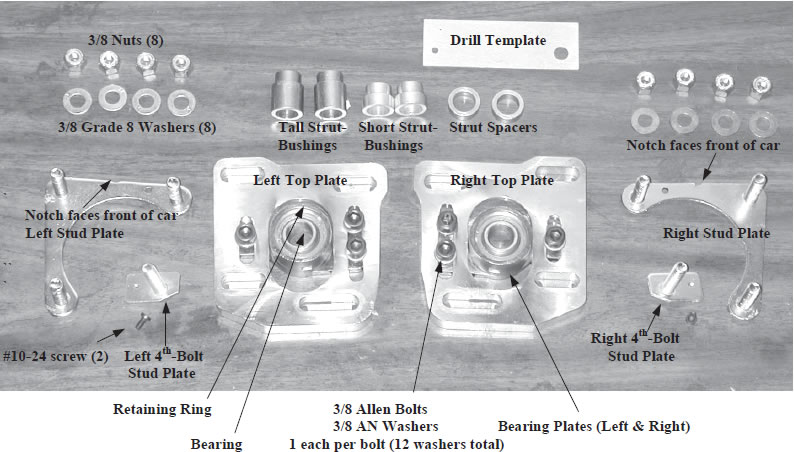
PARTS LIST
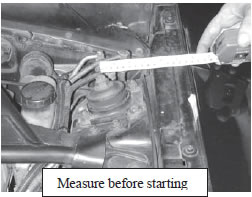
Note: An alignment must be performed after installing the camber plates. If you will be driving the car to the alignment shop, measure the position of the strut before starting. After installing the plates, adjust the strut position to match these measurements for the drive to the alignment shop.
1. Raise the front of the vehicle and support it on jack stands. Remove the front wheels. Consult your owners manual for proper jacking points.
2. Raise one front control arm slightly with a floor jack. Support it just enough to take the weight off the strut, so the jack is slightly loaded.
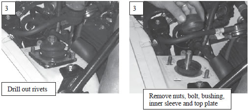
3. Remove the large nut on the top of the strut and the nuts and bolt which hold the factory strut adjustment plate. Note: the easiest way to loosen the strut nut is with an air powered impact wrench. Remove the large top washer, strut bushing, and the steel sleeve inside the bushing. Remove the top plate from the strut tower. There may be a rivet (or two) holding the plate in place. Remove the rivet with a chisel or drill.
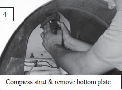
4. Slowly and carefully lower the control arm with the jack so the top of the strut drops most of the way down through the hole in the strut tower. Do not lower the arm too far or the spring may come out suddenly, causing injury. Compress the strut for more clearance by pulling down on the dust boot and remove the bottom plate from under the fender. You will have to pull hard to compress the struts because they are pressurized.
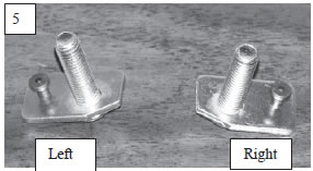
5. Identify which is the left and which is the right 4th-bolt stud plate from the picture. The 4th bolt stud plate is the one with the independent single stud. The angle cut corner goes towards the firewall and engine.
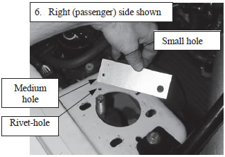
6. Lay the drill template on the strut tower as shown in the pictures. The largest hole goes over the slot at the front, closest to the engine. The medium size hole goes over the small rivet-hole towards the back of the strut tower, closest to the firewall. The smallest hole in the template goes closer to the engine.
7. Insert the 4th-bolt stud plate through the template and strut tower, upside down so the plate rests on top of the strut tower and template - As shown in the picture.
8. Insert the small #10 screw through the template and rivet hole in the tower, as shown in the picture.
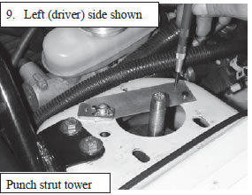
9. Gently pull the forward end of the template and the stud plate away from the engine, towards the fender, to take up any loose “play” in the template. Push the back end of the template towards the engine so the small screw is centered in the rivet hole. Center punch the strut tower through the small hole in the template.
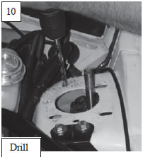
10. Remove the template and drill a 1/8” hole in the strut tower where you marked it. Hold the drill perpendicular to the strut tower and be careful not to let the drill “walk” away from your punch mark. Next enlarge the hole to 25/64”. Use a 3/8” bit if you don’t have a 25/64. Deburr the hole with a file or sandpaper. Deburr the bottom side of the hole also.
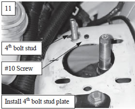
11. Install the 4th-bolt stud plate through the hole from the bottom, with the stud sticking up through the tower. Insert the #10 screw through the rivet hole and thread it into the stud plate. If the screw does not line up with the threaded hole in the stud plate, the drill bit may have “walked” off-center during drilling.
Enlarge the hole with a round file if necessary.
Enlarge the hole you drilled, not the rivet hole. Once the stud plate and screw are in place, tighten the screw with a 3/32 hex (Allen) wrench.
12. Determine the correct strut height adjustment.
The strut mounting height can be adjusted with the Caster Camber plates. The reason you would adjust the height is to ensure that the suspension can move through it’s normal range of motion without running out of travel. On a lowered car that usually means raising the strut up so the suspension can compress further without bottoming. On a drag car sometimes it is beneficial to lower the strut mount so that the front suspension can extend farther at launch without lifting the wheels off of the ground.
In general, the lower the ride height, the stiffer the spring needs to be to prevent bottoming the suspension . Some companies use stiffer springs than others, so there is no one set ride height where you will definitely have a bottoming problem. In addition, not all aftermarket struts are the same length. The accompanying guidelines are general staring points only. Your car may vary.
It is the responsibility of the customer/installer to determine the correct strut height setting. If you encounter a bottoming problem with your spring and strut combination, move the strut to a higher mounting position. If the car has been lowered more than 1&1/2 inches, shorter struts such as Tokico BB3026 or HB3026 are recommended to allow the suspension to compress further without bottoming.
NOTE: these Caster Camber plates are designed to be used with the factory bump stop on the strut. If you are installing new struts, the factory dust cover and bump stop must be transferred to the new struts. The bump stop looks like a rubber donut that rides on the strut around the piston rod, underneath the dust cover.
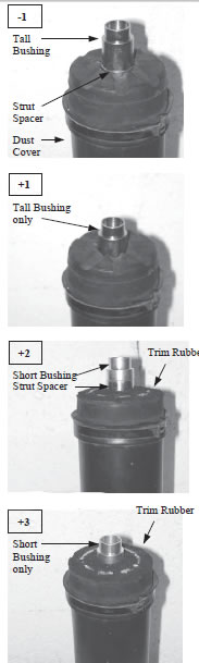
Strut Height is set by the size and number of spacers that are placed on the strut, on top of the dust cover, underneath the camber plate bearing.
Settings:
-1 This lowers the strut mount slightly from stock.. Use this setting for longer strut extension when drag racing or when shorter than stock struts are used with stock height springs.
1 This raises the strut mount slightly from stock. This is the most common general-use setting for stock to 3/4” lowered vehicles with stock length struts, and for lowered vehicles with shorter than stock struts.
2 This raises the strut mount 2 steps above stock. Use with 3/4 to 1-1/2” lowered vehicles. The rubber on the top of the dust cover must be trimmed to run this setting. (See below).
3 This setting is used for cars that are experiencing severe bottoming problems, due to excessive lowering with inadequate spring rates. It is necessary to completely remove all rubber from the dust boot to run this setting. Depending upon your alignment settings, you may have to grind the steel top of the dust cover or leave it out altogether to prevent it from binding against the strut tower. Even if the dust cover is left off, the bump stop must still be used. Also check hood clearance if you are running this setting.
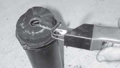
Trimming the Rubber on the Factory Dust Cover:
If you are raising the strut to the 2 or 3 position you will need to trim the rubber off of the top of the factory dust cover to prevent it from interfering with the underside of the strut tower. This can be done with a hacksaw, sander, or any other available tool. Cut down the rubber until you reach the steel support underneath.
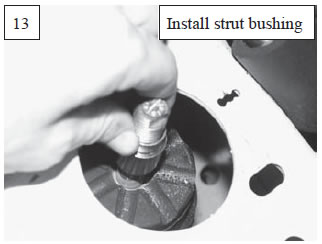
13. After determining the correct bushings and spacers to go under the camber plate bearing in step 12, install the bushing(s) over the top of the strut, so they rest on top of the dust cover.
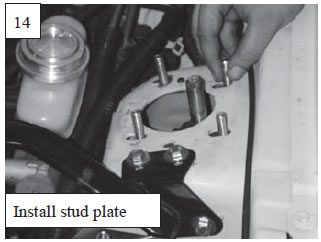
14. Install the Stud Plate in the strut tower by reaching in the wheel well and sliding the plate upward so the studs protrude up through the slots in the strut tower. The NOTCH on the stud plate must face the FRONT of the vehicle. If the notch faces the side of the car you have the left and right stud plates reversed.
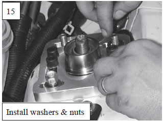
15. Place the Top Plate over the studs on top of the strut tower. The longer slot in the top plate goes over independent “4th” stud. On some cars you may have to move a wiring harness out of the way to make room for the new plates. Install the grade 8 washers over the studs, followed by the 3/8 nuts. Leave the nuts loose for now.
16. Raise the control arm with the jack while lining up the strut with the spherical bearing in the Top Plate. Raise the arm until the strut protrudes all the way through the bearing. If necessary, a long 3/8 drive socket extension can be used to twist the “ball” in the center of the bearing so that it is aligned with the strut.
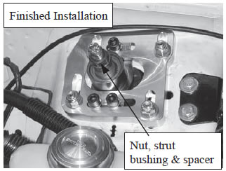
17. Install the other strut bushing over the strut, with the small end facing down. Also install the strut spacer if it wasn’t used underneath the bearing. Line up the strut bushings and push them into the bearing. If the bushings are too tight to push in by hand, use the strut nut to press the bushings in. Install the strut nut and tighten to factory specs (56-90 ft/lb).
18. Tighten the (4) stud plate nuts and (3) Allen bolts . If you will be driving to the alignment shop, position the strut in the same place you measured before you disasembeld the stock stock strut mount, and tighten the nuts & bolts to 25 ft/lb. If aligning the car now, just snug the nuts & bolts.
19. Lower the floor jack under the control arm and repeat steps 2 through 18 on the other side of the car
20. Install the wheels and lower the car.
21. Set the front end alignment (Roll the car back and forth to settle the suspension first). Tighten the nuts and bolts to 25 ft/lb.
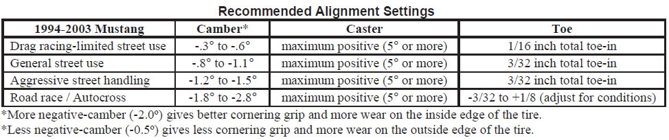
Camber is adjusted by loosening the 4 nuts and moving the top plate left or right (toward or away from the engine).
Caster is adjusted by loosening the 3 socket head bolts and pushing the bearing plate backward or forward. Most Mustangs respond best to increased positive caster. The recommended starting point is to push the struts back towards the firewall, for increased positive caster.
Note: Whenever caster is increased more than 2 degrees beyond factory settings (3.6 degrees is factory spec), bumpsteer should be checked and corrected with offset rack bushings or a “bumpsteer kit” if necessary.
22. Check hood clearance over the outer front stud. This stud comes very close, and depending upon your camber settings and variations between different cars and hoods you may have to file 1/8 inch off the top of the bolt to prevent it from scratching the hood. File the top of the stud after the nut has been installed so that the nut will straighten the top threads when it is removed.